Investigation of high-speed abrasion behavior of an abradable seal rubber in aero-engine fan application
2017-11-20HaijunXUANNaZHANGBinLULijunCHENGWeirongHONG
Haijun XUAN,Na ZHANG,Bin LU,Lijun CHENG,Weirong HONG
aHigh-speed Rotating Machinery Laboratory,College of Energy Engineering,Zhejiang University,Hangzhou 310027,China
bCollaborative Innovation Center for Advanced Aero-engine,Beijing 100083,China
cBeijing Institute of Aeronautical Materials,Aviation Industry Corporation of China,Beijing 100095,China
Investigation of high-speed abrasion behavior of an abradable seal rubber in aero-engine fan application
Haijun XUANa,b,*,Na ZHANGa,b,Bin LUa,b,Lijun CHENGc,Weirong HONGc
aHigh-speed Rotating Machinery Laboratory,College of Energy Engineering,Zhejiang University,Hangzhou 310027,China
bCollaborative Innovation Center for Advanced Aero-engine,Beijing 100083,China
cBeijing Institute of Aeronautical Materials,Aviation Industry Corporation of China,Beijing 100095,China
Abradable seal rubber has been widely used in aero-engine fans to improve their efficiency by reducing the clearance between rotating and stationary components.To investigate the high-speed scraping behavior between a vulcanized silicone rubber and a Ti-6Al-4V fan blade and evaluate the abradable performance of seal rubber,abrasion tests were conducted at a blade tip velocity of 50–300 m/s with an incursion rate of 100 μm/s.The in fluences of the blade tip velocity on the wear mechanism and interaction forces were specially analyzed.It is shown that abrasive wear and pattern wear are the predominant wear mechanisms,and pattern wear can be seen as the emergence and propagation of cracks.With an increase of the blade tip velocity,both of the final incursion depth and wear mass loss of seal rubber exhibit growth trends.The gradual changes of rubbing forces with an increase of rubbing time are the characteristic of abrasive wear,and force curves with unstable mutations are a re flection of pattern wear.At a constant incursion rate of 100 μm/s,the maximum values of interaction forces decrease first and then grow with an increase of the blade tip velocity,and the blade tip velocity of 150 m/s becomes the cut-off point between abrasive wear and pattern wear.
©2017 Production and hosting by Elsevier Ltd.on behalf of Chinese Society of Aeronautics and Astronautics.This is an open access article under the CC BY-NC-ND license(http://creativecommons.org/licenses/by-nc-nd/4.0/).
1.Introduction
The sealing performance of air pathway has a great influence on efficiency and specificfuelconsumption in turbine engines.1,2Research shows that an effective method for improving efficiency and reducing fuel consumption is to reduce the air leakage loss between rotating and stationary components.3,4To minimize engine operating clearance and improve efficiency by limiting gas leakage between engine stages,abradable seals have been installed as rub-tolerant materials by aero-engine manufacturers on the inner walls of stationary engine components.5,6However,a small operating clearance will lead to a transient rubbing interaction between rotating and stationary components because of spindle vibration,deformation,installation error,etc.In general,an abradable seal material serves on fans,compressors,and turbine casings under high-temperature and high-speed working conditions,so it ought to have a lot of excellent comprehensive properties,7such as structural strength,thermal stability,erosion-resistance,8heat-shock resistance and abradability.The design and selection of an abradable seal for a particular position in aero-engines always involve a compromise of conflicting requirements.9It must be weak enough to abrade away with no wear or seal material pickup on the associated blades when in contact with high-speed rotating hardware.10,11The material must also be strong enough to withstand highvelocity gas and particulate erosion.
There are many types of abradable seal materials serving in different parts of aero-engines,such as coating,12honeycomb13,14and seal rubber.Coating has been widely used in high-pressure compressors and turbines because of its hightemperature resistance,and honeycomb is usually brazed on the casing inner surface to protect the labyrinth blade from deformation and wearing under conditions of high temperature and differential pressure.15,16Then for seal rubber,owing to its poor resistance to high temperature,it is usually applied to low-temperature and low-pressure parts with large sizes,such as fans.17In the past 60 years,lots of aero-engine manufacturers and researchers have devoted to analyzing the properties of abradable materials to guide the preparation and composition optimization of seal materials,including abradability.A variety of different approaches has been adopted to research evaluation methods and criteria of abradability and to investigate friction and wear behaviors and wear mechanisms with blade tips.Up till now,a complete theory of their friction and wear behaviors has not been established,and experiments are still the main method.To assess the abradable performance of seal coating,a standard scratch tester was used by Xiao Ma,and ‘progressive abradability hardness” was proposed as an appropriate measure of coating abradability.18,19Yi et al.used the sliding worn volume to evaluate coating abradability based on a wear testing machine using a form of block-ring.20In another paper,Sutter et al.used a pneumatic gun to simulate the interaction between a compressor blade and casing,and the interaction forces between the abradable material and the titanium alloy blade were measured by a load sensor.21However,all these testers failed to re-produce the contact conditions between blade tips and seal materials because of their low velocity or low temperature.
In recent years,to evaluate abradability precisely,a new experimental approach called abradable tester has been developed by many companies and research institutions like Prattamp;Whitney of America,22Sulzer Innotec of Switzerland,23University ofSheffield,24NRC Institute for Aerospace Research of Canada,25ALSTOM and Zhejiang University,26etc.,and the most major characteristic of this tester is that it is able to simulate the high-speed friction and wear processes between blade tips and a seal material under working conditions in aero-engines.With help of this kind of tester,N.Fois et al.investigated the wear of abradable linings,with the result that adhesive transfer and cutting were the dominant mechanisms under low and high incursion rates,respectively.27In another paper,the relationship between the wear behavior,contact forces,and incursion rate was studied,and it was found that low incursion rates resulted in low tangential forces and adhesion,while high incursion rates resulted in higher forces and good cutting.28Bounazef et al.found that material transfer on a blade was minimized by using high velocity and high incursion rate,and the wear map of a BN-SiAl-bounding organic element was obtained.29Zhang et al.studied the highspeed rubbing behavior of labyrinth-honeycomb seals and summarized their wear mechanisms including cutting,compression deformation,smearing,oxidation,adhesive transfer,and thermal ablation.In addition,rubbing force and acceleration during the test were specially analyzed to evaluate the strength of their rubbing behavior.30Xue et al.concluded that frictional heat directly led to the mechanism of material transfer,especially when the linear speed was high and the single pass depth was low.31
As seal rubber has been widely used in various applications and configurations including compressors,gas turbines,and aero engines,a generic investigation that gives broad insights into worn abradable rubber seal behavior is required.However,most of the current research mainly focuses on the abradable performance evaluation of abradable coatings and their wear mechanism investigations.32There is also a lot of research on rubber,but most of them concentrates on basic properties of rubber materials and rubber composite seals.33,34In the available literature,analysis and research on the abradability of seal rubber are very rare,and only Dowson35and his groups have carried out some research work.Through experiments at different velocities and different interaction rates,it was found that abradability,hardness,temperature limits,corrosion resistance,expansion coefficient,and erosion resistance were all important factors that must be considered in selecting the most suitable material,while silicone rubber,aluminum silicon polyester,and nickel-graphite were acceptable abradable materials for centrifugal compressor application.In another paper,36from wear conditions and vibration characteristics,it was confirmed that rubber materials had good abradability to protect labyrinth teeth from wear or heat damage after various tests were run with different unbalance.Even so,experimental data of abradability evaluation and scraping interaction between rubber materials and metal blades are still a serious shortage.Therefore,there is an urgent need to produce more conclusive information on high-speed scraping behavior of seal rubber,especially wear profiles and wear mechanisms under different working conditions.All these research will provide guidance for design,optimization,and selection of seal rubber as well as data support for rotor dynamic analysis.
This paper aims to investigate the high-velocity friction and wear behavior between an abradable silicone rubber material and a Ti6Al4V simulated blade using an abradable tester.The next section presents details of the tester,testing specimens,and testing scheme,as well as nine abrasion tests that were conducted at different blade tip velocities and a constant incursion rate to investigate their influences on the wear mechanism.Then visual rubbing observations,wear debris,wear mass loss,and interaction forces were analyzed to gain insight into the wear mechanism and abradability of the silicone rubber.Finally,results are summarized in the conclusions.
2.Materials and methods
2.1.Test equipment
To simulate the complex interaction between blade tips and seal rubber in aero-engines,an abradable tester has been designed,as shown in Fig.1.The test rig has been described in detail previously in an article,26and a brief summary with modifications made for the present work is given below.A DC motor connected with a belt speeder was selected to drive the flexible shaft to reach the maximum rotating speed of 16000 r/min.A disc with a 500 mm diameter was fitted at the shaft end with a removable blade specimen fixed on the outside,and a dummy blade was fixed at an opposite angle of 180°for balancing.The tester with the current arrangement is capable of rotating with a maximum blade tip velocity of 520 m/s.To implement the incursion movement of a rubber sample,a feeding platform driven by a servo motor was selected with the allowed incursion rate between 5 and 1000 μm/s and a precision of 3 μm/s.A three-dimensional piezoelectric dynamometer with a measurement range of 2500 N was used to measure the interaction forces between the blade and the rubber sample,and force signals were recorded by a high-speed data acquisition system.
2.2.Test materials
A simulated blade with a straight blade structure was designed for abrasion tests,as shown in Fig.2,in order to improve the convenience of machining and installation,and it was connected with the disc through two high-strength bolts.The simulated blade tip is 620 mm in diameter,and the thickness and width of the blade tip are 2 and 22 mm,respectively.The simulated blade and the dummy blade were both fabricated from Ti-6Al-4V.
In tests,a vulcanized silicone rubber with a Shore A hardness of 85 has been selected as the abradable seal material to bear metal blade scraping.This type of silicone rubber,which is normally black and sticky at room temperature,can be molded by casting,and then solid rubber plates are obtained with certain hardness and elasticity after a curing process at specified temperature for a specified time.37,38The rubber samples had a length of 130 mm,a width of 65 mm,and a thickness of 6 mm,as depicted in Fig.2.They were bonded on a metal substrate with glue and bolts before testing.The structures of the simulated blade and rubber samples are presented in Fig.3.
2.3.Testing scheme
To analyze the high-speed scraping behavior between the blade and the rubber material,a series of abrasion tests was carried out under different parameters.In this paper,the influence of the blade tip velocity was studied emphatically,so the blade tip velocity was varied between 50 and 300 m/s with a constant incursion rate of 100 μm/s,as listed in Table 1.The overall incursion depth was kept constant as 1000 μm,and all tests were conducted at room temperature.The incursion depth per passDp(μm)can be described as:
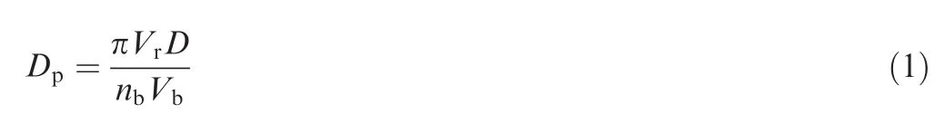
whereVris the incursion rate of the rubber sample(μm/s),Drepresents the turning diameter of the blade tip(m),nbis the number of simulated blades mounted on the disk,andVbis the blade tip velocity(m/s).In our abrasion tests,the incursion depths per pass under different blade tip velocities are given in Table 1.
The process of an abrasion test is illustrated in Fig.4.The simulated blade tip velocity is firstly programmed to gradually reach the target speedVband then kept stable.Next,a rubber sample driven by the radial feeding system feeds in the radial direction to reach the zero position of the incursion depth at a high incursion rate of 500 μm/s,and then it continues moving at the target incursion rateVruntil the total incursion depth reaches 1000 μm.At the end of scraping,the sample retreats in the reverse direction as quickly as possible,and the blade tip velocity gradually decreases to zero.
3.Test results and discussion
3.1.Analysis of rubber samples
The blade tip impacts and scrapes a rubber sample with a high velocity,resulting in damage of the rubber material and wear of the blade.Their impingement and scraping action can be demonstrated from the worn surface morphology,which is one of the most direct characteristics for wear mechanisms investigation.
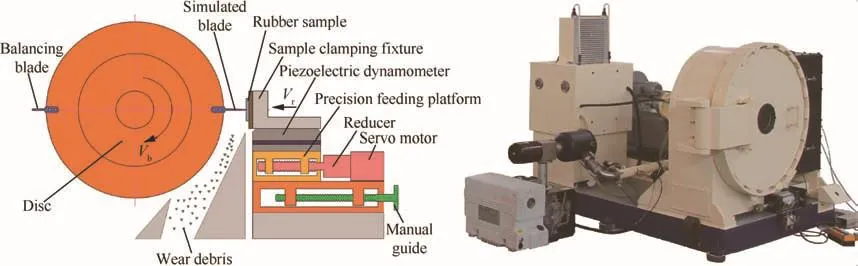
Fig.1 Test schematic diagram(left)and general view(right)of the high-speed abradable test rig.
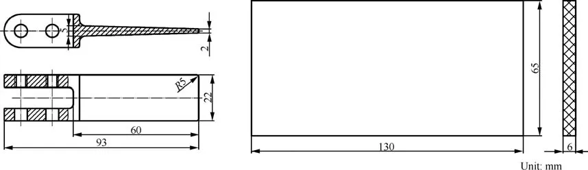
Fig.2 Geometries of the simulated blade(left)and rubber sample(right).
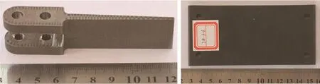
Fig.3 Simulated blade(left)and rubber sample(right)used in abrasion tests.
Table 1 Test parameters used in this work.
Fig.4 Testing process.
Because of the low hardness of rubber and high stiffness of the simulated blade,high-speed scraping did not cause any wear or damage to the blade tip.Worn surface morphologies of silicone rubber samples after tests are shown in Fig.5.The blade scraped rubber samples from left to right,leaving a rectangular scratch with the same width of the blade.It is found that the wear morphologies of rubber samples were different at different blade tip velocities.Under conditions of low linear velocities,a smooth surface with a small roughness is revealed,as shown in Fig.5(a)–(c),which is the typical morphology of abrasive wear.With the increase of the blade tip velocity,much more severe wear is shown.When the blade tip velocity reaches 175 m/s,a rough surface appearance emerges at the end of the scratch(Fig.5(d)),while with the increase of the linear velocity,the surface roughness rises gradually until formation of burrs(Fig.5(e)).The direction of burrs is perpendicular to the scraping direction,and pattern wear is exposed on the rubber surface.Fig.6 explains the formatting mechanism of pattern wear.Because ofits viscoelastic performance,the rubber sample presents a serrated surface,and the intersection angle between the front crack of a saw tooth and the rubber surface is θ.When the blade tip sweeps through the surface,the saw tooth moves backward with the blade and becomes tightened with severe bending deformation.Once the blade moves past the tooth,it restores to relax.The friction force will result in a growth of the crack and gradual wear of the saw tooth.The scraping behavior between the blade and rubber can be considered as an expanding process of the cracks in the roots of saw teeth,and θ is the angle of the crack propagation.The area covered by burrs gradually expands forwards from the end of the scratch.When the blade tip velocity reaches 300 m/s,80 percent of the scratch area has been covered by burrs.In addition,wear morphologies show that with a low velocity,which is less than 175 m/s,the end edge of the scratch is smooth and straight,but when the mechanism of pattern wear appears,an arc-shaped and uneven edge is presented at the end of the scratch owing to the drag and tear between serrated burrs.
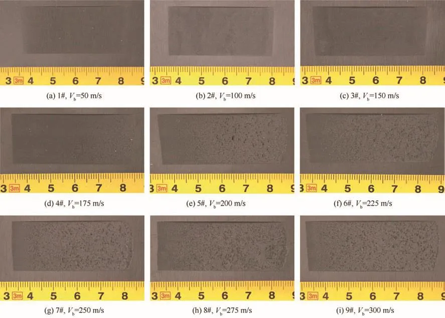
Fig.5 Worn surface morphologies of rubber samples after abrasion tests.
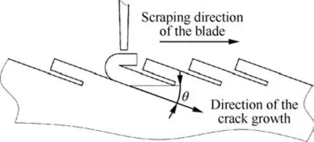
Fig.6 Mechanism of pattern wear.
Wear debris is another important characterization of wear mechanism.Fig.7 shows three typical kinds of wear debris under different blade tip velocities.When a sharp blade tip with a low linear velocity is in contact with the rubber surface,local stress concentration happens on the surface,and the rubber material is usually cut and broken into fine powders with a uniform size of less than 0.5 mm,as shown in Fig.7(a).With an increase of the blade tip velocity,the impact energy rises,and pattern wear gradually replaces abrasive wear as the main wear mechanism.As a result of crack generation and growth,wear debris of pattern wear is mainly strips and flakes.At a blade tip velocity of 225 m/s,debris presents an irregular shape with a maximum size of 1–2 mm,as shown in Fig.7(b).When the blade tip velocity continues to increase,a longer growth length of the crack and greater wear of saw teeth occur on the rubber sample,resulting in that the debris size is up to 3–5 mm,as shown in Fig.7(c).
3.2.Analysis of final incursion depth and wear mass
Rubber is a viscoelastic material with low hardness,so elastic deformation can be produced on the contact zone of a rubber sample because of the extrusion stress when it is scraped by a metal blade.The elastic deformation of the rubber sample is calledDe-r,which depends on the properties of silicone rubber and the structure of the simulated blade.On the other hand,elongation deformationDe-bwill occur on the high-speed rotating disc and the simulated blade due to a centrifugal force.The final incursion depth is comprehensively in fluenced by elastic deformation of rubber and elongation deformation of the blade,as shown in Fig.8.Then the final incursion depthDfinalcan be described as:
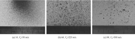
Fig.7 Wear debris of rubber samples after abrasion tests.

whereDtis the target incursion depth set before an abrasion test.At a low blade tip velocity,the elongation deformationDe-bis lower than the elastic deformation of a rubber sampleDe-r,with the result that the final incursion depthDfinalis lower than the target incursion depthDt.However,whenDe-bis higher thanDe-r,the final incursion depth will be higher than the target incursion depth.Fig.9 shows the final incursion depths of different rubber samples.It is found that with an increase of the blade tip velocity,the final incursion depth shows a gradual increase.For tests 1#,2#,and 3#,the final incursion depths are lower than 1000 μm because of the smaller elongation deformation of the blade at a lower blade tip velocity,while for test 4#to test 9#at high blade tip velocities,the final incursion depths are higher than 1000 μm.
Because the hardness of the silicone rubber material is obviously lower than that of the blade material,there is almost no damage to the blade when a high-speed rub-impact occurs.The weights of the rubber samples were measured by an electronic balance with a precision of 0.01 g before and after abrasion tests.The initial weight of a rubber sample is about 46.50 g,and the theoretical mass loss with an incursion depth of 1000 μm is 0.68 g.The actual wear mass losses of rubber samples are shown in Fig.9.It is found that the wear mass loss exhibits a growth trend with an increase of the blade tip velocity.Elongation deformation of the blade leads to a greater final incursion depth,which has a direct impact on the wear mass loss of a rubber sample.Furthermore,the change of the wear mechanism also makes a contribution to the increase of the wear mass loss.Pattern wear under a high blade tip velocity causes drag and tear between rubber materials,with a result that the ultimate wear mass loss is greater than the theoretical value.
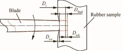
Fig.8 Diagram of the final incursion depth.
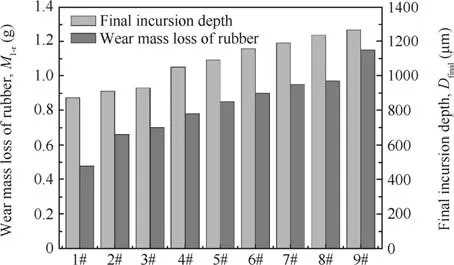
Fig.9 Final incursion depths and wear mass losses of rubber samples for different abrasion tests.
3.3.Analysis of interaction forces
When the blade tip sweeps through the rubber surface,pulse forces will be produced in radial and tangential directions,and then an attenuation response will generate because of the damping effect of the force measuring system.22Typical rubbing force responses of a single cycle and several cycles are illustrated in Fig.10.For a single rubbing cycle,the maximum amplitude is useful for the description of the rubbing force.Periodic attenuation responses with different amplitudes are revealed from rubbing forces,and the cycle is the time to finish a rotation for one blade.
Fig.11 illustrates the radial and tangential forces measured by a piezoelectric dynamometer during the rubbing process at different blade tip linear velocities.It is found that the changing trend of the radial force is similar to that of the tangential force,and the scraping process can be reflected directly by analysis of interaction force curves.For test 2#at a blade tip velocity of 100 m/s(Fig.11(a)),radial and tangential forces show gradual changes with an increase of rubbing time,without mutation in the entire process of rubbing.The stable change of rubbing forces helps to understand the smooth rubbing surface with slight roughness,which has been shown in Fig.5(b),and it also corresponds to abrasive wear.The rubbing force curves of test 2#can be divided into three stages.The first one(0–1 s)represents the elastic deformation of a rubber sample where forces are close to zero.At this stage,the blade and the rubber sample are in contact with each other without wear of rubber,which is a unique and important characteristic for sealing rubber based on its good elasticity.The second stage is the time with increasing forces,which is 1–3.5 s for the radial force and 1–3.25 s for the tangential one.At this stage,the rubbing forces show a linear growth trend with the time.The rest time belongs to the third stage when the radial force gradually decreases with time and the tangential one keeps stable until the end of the scraping action.
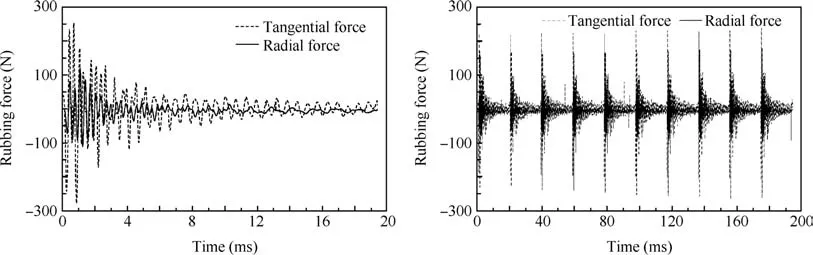
Fig.10 Typical force responses for one cycle(left)and ten rubbing cycles(right)(Vb=100 m/s).
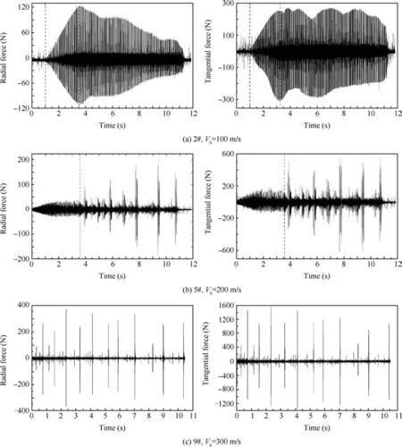
Fig.11 Curves of interaction forces for different abrasion tests.

Fig.12 Maximum interaction forces for nine abrasion tests.
The rubbing force curves of test 5#at a blade tip velocity of 200 m/s(Fig.11(b))can be divided into two stages.The first one(0–3.6 s)represents the smooth force change in both radial and tangential directions,which is consistent with the characteristic of the abrasive wear mechanism.When the rubbing time reaches 3.6 s and the incursion depth reaches 360 μm,interaction forces show a sudden increase,which marks the ending of abrasive wear and the beginning of pattern wear.The rubbing time after 3.6 s belongs to the second stage,in which force curves show many mutations with unequal intervals,which are usually in accordance with the emergence and propagation of cracks.It is found that every mutation of interaction forces corresponds to several scrapes with large wear debris because of the remarkable viscoelasticity of seal rubber,and then in the subsequent period of scraping,a smaller force is enough to scrape off the rest material.Thus,both abrasive wear and pattern wear are clearly revealed from its rubbing force curves,which are the same as the surface morphology of test 5#in Fig.5(e).With an increase of the blade tip velocity,the duration of the smoothing stage gradually decreases and the time with mutation extends progressively until the blade tip velocity reaches 300 m/s(test 9#).As shown in Fig.11(c),the smoothing stage almost disappears,and the whole curves are covered by unstable mutations.Then pattern wear is predominant and the rubbing surface is almost covered by burrs.
The maximum interaction force is selected to evaluate the intensity of the scraping behavior between the seal couple because it determines the most serious wear or damage.Fig.12 illustrates the maximum radial and tangential forces at different blade tip velocities.For silicone rubber,the tangential force is much higher than the radial one,resulting in a rubbing coefficient greater than two.At a constant incursion rate of 100 μm/s,it is found that the interaction forces decrease with an increase of the blade tip velocity when it is lower than 150 m/s.Under these conditions,abrasive wear is the main mechanism with tiny chips,and an increase of the blade tip velocity means a decrease of the incursion depth per pass and a smaller wear mass per pass,resulting in a reduction of the rubbing force.However,when the blade tip velocity is higher than 150 m/s,the pattern wear mechanism becomes much more apparent and a higher blade tip velocity means much more scraping energy,resulting in an increase of interaction forces.As a result,the maximum forces of nine abrasion tests show the trend offirst a decrease and then an increase in Fig.12.Close to a blade tip velocity of 150 m/s,the wear mechanism changes from abrasive wear to pattern wear,with the minimum interaction forces in tangential and radial directions.
4.Conclusions
Seal rubber has been widely used on the inner side of aeroengine fan casing to improve efficiency through minimizing clearance and decreasing blade tip leakage.To study the wear mechanism and the interaction force response law,a series of high-speed abrasion tests was conducted between an abradable silicone rubber and a simulated blade of Ti-6Al-4V with a blade tip velocity of 50–300 m/s and a constant incursion rate of 100 μm/s to investigate the high-speed scraping behavior.It is concluded that:
(1)Abrasive wear and pattern wear are the predominant wear mechanisms when a metal blade scrapes a rubber sample.With an increase of the blade tip velocity,abrasive wear is gradually replaced by pattern wear,which can be seen as the emergence and propagation of cracks.
(2)Both of the final incursion depth and wear mass loss of seal rubber exhibit growth trends with an increase of the blade tip velocity.The final incursion depth of the rubber is comprehensively determined by the elastic deformation of rubber and the centrifugal elongation of the blade.The increase of the wear mass loss is influenced significantly by the increase of the final incursion depth and the change of the wear mechanism.
(3)There is an obvious mark of the wear mechanism.During one scraping process,radial and tangential forces show gradual changes with an increase of the rubbing time at a low blade tip velocity,which results in a smooth rubbing surface and a low roughness with abrasive wear.As pattern wear happens at a high blade tip velocity,the force curves show many unstable mutations,resulting in a rubbing surface covered by burrs.
Acknowledgements
This work was supported by the Fundamental Research Funds for the Central Universities(No.2013XZZX005).The authors also gratefully acknowledge Beijing Institute of Aeronautical Materials for providing abradable seal rubber samples.
1.Faraoun HI,Seichepine JL,Coddet C,Aourag H,Zwick J,Hopkins N,et al.Modelling route for abradable coatings.Surf Coat Technol2006;200(22–23):6578–82.
2.Chen LS,Wang YL,Lu JH,Zhang H.Development of study and application of aeroengine sealing technology.Aeronaut Manuf Technol2008;8:82–95[Chinese].
3.Ghasripoor F,Dorfman M,Schmid R.Abradables improve gas turbine efficiency.Mater World1997;5(6):328–30.
4.Dorfman M,Erning U,Mallon J.Gas turbines use ‘abradable’coatings for clearance-control seal.Seal Technol2002;2002(1):7–8.5.DeMasi-Marcin JT,Gupta DK.Protective coatings in the gas turbine engine.Surf Coat Technol1994;68–69:1–9.
6.Chupp RE,Ghasripoor F,Turnquist NA,Demiroglu M,Aksit MF.Advanced seals for industrial turbine applications:dynamic seal development.J Propul Power2002;18(6):1260–6.
7.Dalzell WJ,Sanders SA,Crawford GL,Walden FC,Woodard WJ.Abradable seal with improved properties.Seal Technol2002;2002(8):14–5.
8.Yi MZ,Huang BY,He JW.Erosion wear behaviour and model of abradable seal coating.Wear2002;252(1–2):9–15.
9.Schricker B.Using fiber metal abradable seals in aerospace turbine applications.Aerosp Defen Technol[Internet].2011 Oct[cited 2016 Jul 25];2011.pp.1–3.Available from: <http://www.aerodefensetech.com/component/content/article/adt/features/feature-articles/11459>.
10.Rathmann U,Olmes S,Simeon A.Sealing technology:rub test rig for abrasive/abradable systemsASME turbo expo 2007:power for land,sea,and air;2007 May 14–17;Montreal,Canada.New York:ASME;2007.p.223–8.
11.Chappel DE,Vo L,Howe HW.Gas path blade tip seals:abradable seal material testing at utility gas and steam turbine operating conditionsASME turbo expo 2001:power for land,sea,and air;2001 Jun 4–7;New Orleans,Louisiana,USA.New York:ASME;2001.p.112–22.
12.Delebarre C,Wagner V,Paris JY,Dessein G,Denape J,Gurt-Santanach J.An experimental study of the high speed interaction between a labyrinth seal and an abradable coating in a turboengine application.Wear2014;316(1–2):109–18.
13.Potter DJ,Chai YW,Tatlock GJ.Improvements in honeycomb abradable seals.Mater High Temp2009;26(2):127–35.
14.Draskovich BS,Frani NE,Joseph SS,Narasimhan D,inventor;AlliedSignal Inc.,assignee.Abrasive tip/abradable shroud system and method for gas turbine compressor clearance control.United States patent US 5704759;1998 January 6.
15.Pychynski T,Ho¨efler C,Bauer HJ.Experimental study on the friction contact between a labyrinth seal fin and a honeycomb stator.J Eng Gas Turb Power2015;138(6):062501.
16.Shen H,Zheng TH,Chen YJ.Improvement of aero-engine sealing technology.Gas Turb Exp Res2011;24(4):51–5[Chinese].
17.Jiang YQ,Shen EM,Wang ZH.Application of non-metal seal materials on civil engine.Aeroengine2010;36(6):46–9[Chinese].
18.Ma X,Matthews A.Investigation of abradable seal coating performance using scratch testing.Surf Coat Technol2007;202(4–7):1214–20.
19.Ma X,Matthews A.Evaluation of abradable seal coating mechanical properties.Wear2009;267(9–10):1501–10.
20.Yi MZ,He JW,Huang BY,Zhou HJ.Friction and wear behavior and abradability of abradable seal coating.Wear1999;231(1):47–53.
21.Sutter G,Philippon S,Garcin F.Dynamic analysis of the interaction between an abradable material and a titanium alloy.Wear2006;261(5–6):686–92.
22.Bill RC,Shiembob LT.Friction and wear of sintered fibermetal abradable seal materials.J Lubr Technol1977;99(4):421–7.
23.Bardi U,Giolli C,Scrivani A,Rizzi G,Borgioli F,Fossati A,et al.Development and investigation on new composite and ceramic coatings as possible abradable seals.J Therm Spray Technol2008;17(5–6):805–11.
24.Stringer J,Marshall MB.High speed wear testing of an abradable coating.Wear2012;294–295(31):257–63.
25.Dadouche A,Conlon MJ,Dmochowski W.Experimental evaluation of abradable seal performance at high temperatureASME turbo expo 2008:power for land,sea,and air;2008 Jun 9–13;Berlin,Germany.Ottawa:National Research Council of Canada;2008.p.143–50.
26.Zhang N,Shen J,Xuan HJ,Hu YQ,Hong WR.Evaluation of an AlSi-polyester abradable seal coating performance using hightemperature and high-velocity abrasion tests.Proc IMechE Part J:J Eng Tribol2016;230(7):842–51.
27.Fois N,Stringer J,Marshall MB.Adhesive transfer in aero-engine abradable linings contact.Wear2013;304(1–2):202–10.
28.Fois N,Watson M,Stringer J,Marshall MB.An investigation of the relationship between wear and contact force for abradable materials.Proc IMechE Part J:J Eng Tribol2015;229(2):136–50.
29.Bounazef M,Guessasma S,Saadi BA.The wear,deterioration and transformation phenomena of abradable coating BN-SiAl-bounding organic element,caused by the friction between the blades and the turbine casing.Mater Lett2004;58(27–28):3375–80.
30.Zhang N,Xuan HJ,Guo XJ,Guan CP,Hong WR.Investigation of high-speed rubbing behavior of labyrinth-honeycomb seal for turbine engine application.J Zhejiang Univ-SC A(Appl Phys Eng)2016;17(12):947–60.
31.Xue WH,Gao SY,Duan DL,Liu Y,Li S.Material transfer behavior between a Ti6Al4V blade and an aluminum hexagonal boron nitride abradable coating during high-speed rubbing.Wear2015;322–323:76–90.
32.Chupp RE,Lau YC,Ghaspripoor F,Baidwin DJ,Ng C,McGovern T,et al.Development of higher temperature abradable seals for gas turbine applicationsASME turbo expo 2004:power for land,sea,and air;2004 Jun 14–17;Vienna,Austria.New York:ASME;2004.p.221–9.
33.Ke YC,Yao XF,Yang H,He Q.A measuring method of gas leakage along the contact interface of the stripped tuber seals.Measurement2015;61:299–304.
34.Hu G,Zhang P,Wang GR,Zhang M,Li M.The influence of rubber material on sealing performance of packing element in compression packer.J Nat Gas Sci Eng2017;38:120–38.
35.Dowson P,Ross SL,Schuster C.The investigation of suitability of abradable seal materials for application in centrifugal compressors and steam turbines.Proc Twent Turbomach Symp1991;1991(1):77–90.
36.Dowson P,Walker MS,Watson AP.Development of abradable and rub-tolerant seal materials for application in centrifugal compressors and steam turbines.Seal Technol2004;2004(12):5–10.
37.Ma X,Zhang YH,Guo F,Li ZY.Repair technology of PW4000 engine’s low-pressure compressor stator and duct components.Aeronaut Manuf Technol2006;9:52–4[Chinese].
38.Li WH,Su D,Xin YQ,Ma YF.The application of components filled in rubber in aero-engines.Aeronaut Sci Technol2010;4:27–9[Chinese].
25 July 2016;revised 16 December 2016;accepted 3 January 2017
Available online 20 April 2017
*Corresponding author at:High-speed Rotating Machinery Laboratory,College of Energy Engineering,Zhejiang University,Hangzhou 310027,China.
E-mail address:marine@zju.edu.cn(H.XUAN).
Peer review under responsibility of Editorial Committee of CJA.
Production and hosting by Elsevier
http://dx.doi.org/10.1016/j.cja.2017.02.019
1000-9361©2017 Production and hosting by Elsevier Ltd.on behalf of Chinese Society of Aeronautics and Astronautics.
This is an open access article under the CC BY-NC-ND license(http://creativecommons.org/licenses/by-nc-nd/4.0/).
Abradability;
Abrasion test equipment;
Aero-engine;
Silicone seal rubber;
Wear mechanism
杂志排行
CHINESE JOURNAL OF AERONAUTICS的其它文章
- Wake structure and similar behavior of wake profiles downstream of a plunging airfoil
- Self-sustained oscillation for compressible cylindrical cavity flows
- Numerical studies of static aeroelastic effects on grid fin aerodynamic performances
- A new vortex sheet model for simulating aircraft wake vortex evolution
- Linear stability analysis of interactions between mixing layer and boundary layer flows
- Aerodynamic multi-objective integrated optimization based on principal component analysis