Dynamic performance of a C/C composite finger seal in a tilting mode
2017-11-20HailinZHAOGuodingCHENLinaWANGHuaSUFeiLU
Hailin ZHAO,Guoding CHEN,Li’na WANG,Hua SU,Fei LU
School of Mechanical Engineering,Northwestern Polytechnical University,Xi’an 710072,China
Dynamic performance of a C/C composite finger seal in a tilting mode
Hailin ZHAO,Guoding CHEN*,Li’na WANG,Hua SU,Fei LU
School of Mechanical Engineering,Northwestern Polytechnical University,Xi’an 710072,China
The complex operating state of aeroengines has an impact on the performance of finger seals.However,little work has been focused on the issue and the dynamic performance of finger seals is also rarely studied.Therefore,a distributed mass equivalent model considering working conditions is proposed in this paper for solving the existing problems.The effects of the fiber bundle density and the preparation direction of the fiber bundle of a C/C composite on the dynamic performance of a finger seal are investigated in rotor tilt based on the proposed model.The difference between the C/C composite finger seal performances under the rotor precession and nutation tilt cases is also investigated.The results show that the fiber bundle density and the preparation direction of the fiber bundle have an influence on the dynamic performance of the finger seal as rotor tilt is considered,and the dynamic performance of the finger seal is different in the two kinds of tilting modes.In addition,a novel method for design of finger seals is presented based on the contact pressure between finger boots and the rotor.Finger seals with good leakage rates and low wear can be acquired in this method.
©2016 Chinese Society of Aeronautics and Astronautics.Production and hosting by Elsevier Ltd.This is an open access article under the CC BY-NC-NDlicense(http://creativecommons.org/licenses/by-nc-nd/4.0/).
1.Introduction
Continuous improvement of an aero-engine’s performance leads to more stringent requirements on the performances of seal devices located in it,and the quality of seals has become one of the important factors that restrict further improvement of the performance of an aero-engine.A finger seal can follow the running rotor compliantly and adapt the shaft offset without any damage to the integrity of the seal for its flexibility,and it also shows the advantages of high performance and low cost when compared to conventional labyrinth and brush seals;therefore,it has a potential application in aero-engine systems.For these reasons,finger seals have received more and more attentions in recent years.1–4
A finger seal operates under dynamic conditions and the analysis ofits dynamic performance is complicated.To solve this problem,a method in which a finger seal was regarded as a spring-mass equivalent dynamic model was proposed,which can reduce the complexity of dynamic analysis and obtain the dynamic performance with acceptable accuracy.Braun et al.5,6made a padded finger seal equivalent to a lumped mass-spring-damp model,in which the influence of the friction between finger elements(or between the finger element and the aft cover plate)was neglected,and the gas film was equivalent to the gas film stiffness and gas film damping.The authors analyzed the motion of the padded finger seal along with the rotor movement based on the model,and their work revealed the parameters that affected the motion of the finger seal and provided a theoretical foundation for design of finger seals with good performance.Marie7developed a two-degree-of-freedom lumped mass model in which only the friction between the low-pressure finger element and the aft cover plate was considered to study the padded finger seal,the structural stiffness of the finger seal related to structural parameters was calculated,and the gas film dynamic stiffness coefficients of the finger seal as a function of the rotor speed,gas film clearance and structural parameters were established theoretically.The author proposed that the gas film clearance could be controlled by varying the pressure differential and rotor speed when the finger seal geometrical parameters were held at constants,in order to achieve good sealing performance and wear behavior for the finger seal.Su and Chen8analyzed the hysteresis and contact performance of a finger seal with a lumped mass equivalent dynamic model as well as studied a dynamic design approach for a finger seal with low hysteresis and low wear.The authors also performed a contrast analysis of the dynamic and static hysteresis of the finger seal,and the results showed the necessity of dynamic performance analysis of the finger seal.Chen et al.9treated a multiple superimposed Co-base alloy finger seal as an assembly of distributed mass,considered the coupling effect between the finger elements,and built an equivalent dynamic model based on the distributed mass method.They analyzed the dynamic displacement response of the finger seal as well as proposed the calculation methods of the leakage flow rate and the contact pressure between the finger stick and the rotor.The authors also demonstrated the superiority of the equivalent dynamic model based on the distributed mass method compared to that based on the lumped mass method.Du et al.10,11carried out a dynamic performance analysis by a semianalytical method,in which the leakage of a finger seal was obtained by solving the Reynolds equation under the premise that the leakage clearance was acquired,and the main factors affecting the leakage performance were also analyzed.
Considering the excellent self-lubricating property of C/C composites,they are applied in finger seal component preparation to improve the seal performance,which may be a most feasible solution to reduce the hysteresis effect of a finger seal when the wear life is ensured;therefore,many efforts have been made on researching the application of C/C composites in finger seals in recent years.Lu et al.12evaluated the macroscopic elastic properties of a 2.5D C/C composite by calculating its stiffness matrix with the constituent material properties,and established a finite model for the dynamic performance analysis of a C/C composite finger seal.The authors also studied the impacts of yarn density and yarn braided patterns on the dynamic performance of the finger seal,and their work supported the possibility of applying C/C composites in preparation of finger seals.Chen et al.13analyzed the dynamic performance of a 2.5D composite finger seal based on the equivalent model of distributed mass,and compared the performance with that of a Co-base alloy finger seal.Their research indicated that the leakage rate of the Co-base alloy finger seal is smaller than that of the 2.5D C/C composite finger seal,but the contact pressure is greater for its structural stiffness being greater;therefore,the wear life of the 2.5D C/C composite finger seal is much longer compared to that of the Co-base alloy finger seal.
For an aero-engine,the complicated and hostile operating environment of the rotor can reflect the harsh working conditions of seal devices,including the influence of rotor tilt.However,the effect of rotor tilt was not taken into account in previous works,so it may be too complicated to consider the impact.Note that an inclination of the aero-engine rotor is inevitable,so it is necessary to conduct dynamic analysis considering rotor tilt,which not only extends the research on dynamic performance of finger seals,but also provides necessary technical reserves for the application of finger seals in engineering.
This paper develops a distributed mass equivalent dynamic model considering precession tilt and nutation tilt of the rotor.The influences of the fiber bundle density and the preparation direction of the fiber bundle on the dynamic performance of a finger seal are studied based on the model,and the difference between the dynamic performances of the finger seal in both tilt modes is also analyzed.The work in this article contributes to the practical application of the finger seal dynamic analysis technology in engineering analysis design,and also perfects the theoretical system and method of dynamics of finger seals to a certain extent.
2.Distributed equivalent model
2.1.Structure of the finger seal
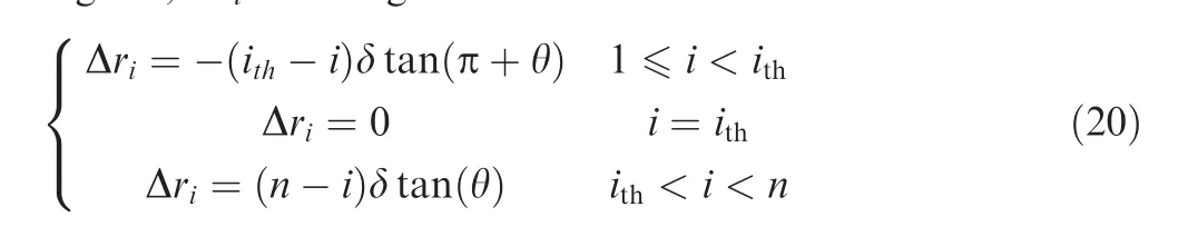
A finger seal is composed of several finger elements and each finger element is shaped by a series of flexible finger sticks arranged at a regular space in the circumferential direction.Multiple staggered and superimposed finger elements are held by a forward cover plate and an aft cover plate,all of which are fixed by rivets.As shown in Fig.1,Dwis the outside diameter of the finger seal;Deis the base diameter of the finger seal;Rcis the seal finger stick arc radius;Dccis the central diameter of the stick circle;Dris the rotor diameter;a finger boot is a part of a finger stick which is in contact with the rotor,andh'is the height of finger boots;β is the repeat angle;and δ is the thickness of finger elements.
2.2.Equivalent model of the finger seal
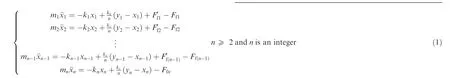
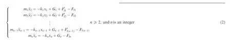
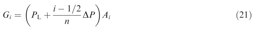
The mechanical behavior between the multiple superimposed finger seal and the rotor can be described by the distributed mass equivalent dynamic model shown in Fig.2.Due to the cyclic symmetrical structure of the finger seal,a single finger stick in each finger element is selected as the research issue.In Fig.2,miandkiare the equivalent mass and equivalent structural stiffness of one finger stick in theith finger element,respectively;FfiandF’fiare the friction forces between adjacent finger elements or between the finger element and the aft cover plate;xiis the displacement response of one finger stick in theith finger element.The state when finger sticks are in contact with the rotor is presented in Fig.2(a),in whichkcis the contact stiffness coefficient between one finger stick and the rotor;yirepresents the displacement excitation of the rotor acting on one finger stick in theith finger element.Note that the displacement excitations of the rotor acting on each finger stick are different when rotor tilt is considered.Fig.2(b)shows the state when finger sticks are separated from the rotor,in which due to the clearance between finger boots and the rotor,the fluid pressure works,andGirepresents the fluid pressure acting on finger boots.The models shown in Fig.2(a)and in Fig.2(b)indicate that the operation of the finger seal system is forced damped vibration.In this article,the finger elements number starts from the low-pressure finger element.

Fig.1 Finger seal geometrical structure.
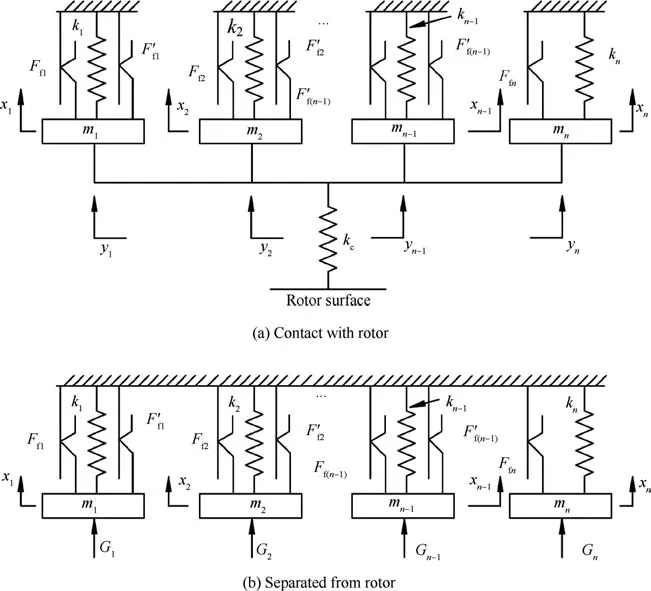
Fig.2 Distributed mass equivalent model of the finger seal.
Due to rotor tilt,some finger sticks in the finger elements bear contact pressure,while the others are separated from the rotor,and it is generally considered that the phase difference between the displacement excitations of the rotor in these two regions is 180o.That is,when rotor tilt is considered, finger sticks of some finger elements are in contact with the rotor,while those of the other elements are not in contact with the rotor.
A force analysis on every distributed mass is carried out.According to Newton’s second law,the differential equations with damped forced vibration of the finger seal are deduced.
When finger sticks are in contact with the rotor,the differential equation of the finger seal with damped forced vibration can be written as
When finger sticks are separated from the rotor,the corresponding differential equation with damped forced vibration for the finger seal is given as follows
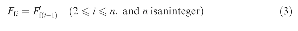
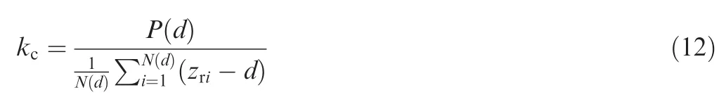
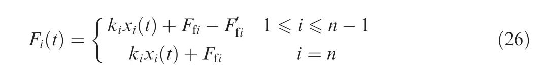
wherenis the number of finger elements,and the relationship betweenFfiandF’fiis defined as
2.3.Equivalent parameters
The equivalent parameters of the distributed mass equivalent dynamic model are determined by the finger seal structural parameters and working conditions.
2.3.1.Equivalent mass
A single finger stick in each finger element is regarded as an equivalent lumped mass in the distributed mass equivalent dynamic model;therefore,the finger seal with multiple superimposed finger elements can be equivalent to an equivalent system based on distributed mass.The equivalent massmican be derived as14
whereNis the number of finger sticks in every finger element;lis the finger stick length;ρ is the density of finger elements;his the width of finger sticks;x(z)is the dimensionless static displacement of the arbitrary mass point in a finger stick.
2.3.2.Equivalent structural stiffness
Applying a radial loadFto a finger boot,then the displacement of the finger boot Δliis calculated by the finite element method,and the ratio of the radial load to the displacement can be defined as the equivalent structural stiffness as
2.3.3.Contact stiffness coefficient
Finger boots and the rotor are in contact with rough surfaces.However,it is transformed into a contact between a smooth rigid surface and a rough elastic surface in this article.Assuming that the asperity deformation of the elastic surface under a normal load is linear elastic,then the contact load between the two surfaces can be expressed as15,16
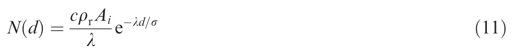
where φ(z)is the distribution function of the asperity heights;ρris the density of asperities;Aiis the contact area between a finger boot and the rotor;Eis the equivalent modulus of elasticity;Ris the average equivalent curvature radius of asperities;dis the average distance between the rough surface and the smooth surface;andzris the asperity heights.
Supposing that the asperity heights are in a normal distribution,for convenience,an exponential function is used to fit the curve above the mean value in the normal distribution,and then the contact loadP(d)can be given as
wherecand λ are the fitting coefficients of the exponential distribution of the asperity heights;σ is the root-mean-square roughness of the rough surface,which is defined as
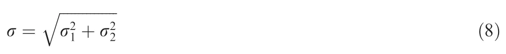
where σ1and σ2are the root-mean-square roughness of the rotor surface and the finger boot surface,respectively.
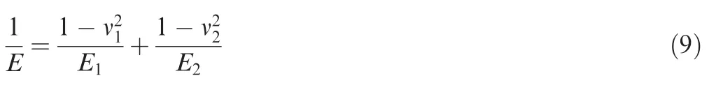
The equivalent modulus of elasticity is defined as in whichE1andE2are the elastic modulus of finger sticks and the rotor,respectively;ν1and ν2are the Poisson ratios of finger sticks and the rotor.
The average equivalent curvature radius of asperities is expressed as
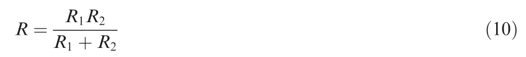
whereR1andR2are the average curvature radii of the rotor surface and asperities of the finger boot surface,respectively.
According to the experimental work of Shi17and Zhao18,Rand ρrcan be calculated by the arithmetic average roughnessRaof the rough surface.
The number of asperities in contact with the rotor surface is given as
As the average distancedis defined,the contact stiffness coefficient between each finger boot and the rotor is defined as the ratio of the contact load to the average deformation of asperities,and the expression is given as follows
2.3.4.Friction force of the finger seal system
There exist contact forces between adjacent finger elements(or between the low-pressure finger element and the aft cover plate),and once a finger stick has a relative motion with respect to a neighboring finger element(or the aft plate),a friction force is generated to hinder the movement of the finger stick in the radial direction.
The friction between the aft cover plate and the first finger element,as well as between two neighboring finger elements can be expressed as
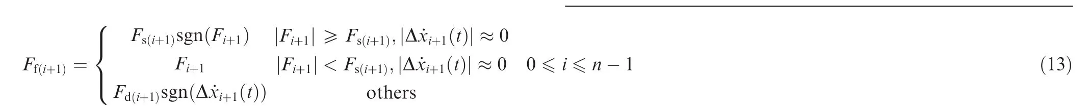
in whichfslandfdlare the static and dynamic friction coefficients between the aft cover plate and the first finger element(l=1)(or between two adjacent finger elements(l=2)),respectively;Al(t)means the corresponding contact area.
Fi+1represents the resultant force except the frictionFf(i+1)acting on a finger stick in the(i+1)th finger element,when
the finger boot and the rotor are in and out of contact,respectively,which can be expressed as follows
whereFf(i+2)is the friction when the(i+1)th finger element acts on the(i+2)th finger element,which can be calculated by Eq.(13).Note that the resultant force acting on the first finger element can also be obtained based on Eqs.(16)and(17).
The friction could be acquired by solving Eqs.(13)–(17).
2.4.Displacement excitation of the rotor
Considering the in fluences of rotor unbalance mass and rotor tilt,the expression of the displacement excitation acting on a finger stick is given by

where ω is the angular velocity of the rotor;Δris the radial displacement amplitude of the rotor caused by its unbalance mass;tis the time;Δriis the value of rotor tilt corresponding to theith finger element,which is related to the thickness of that finger element and the incline angle of the rotor.
As Δri=0,the corresponding finger element is defined as the standard finger element,and it is noted asith.When the phases of the displacement excitations acting on all the finger elements are consistent,rotor tilt is regarded as precession tilt,the standard finger element is the first finger element(ith=1),and the value of rotor tilt can be expressed as

where θ is the incline angle of the rotor.
When the phases of the displacement excitations acting on all the finger elements are not consistent,rotor tilt is precession tilt,and the standard finger element is the middle finger element(ith=n/2).Assuming that the phase difference is 180 degrees,Δrican be given as follows
2.5.Fluid pressure between finger boots and the rotor
As the clearance between finger boots and the rotor occurs,there exists a fluid pressure acting on finger boots.The fluid pressure is related to the pressure difference of the seal system and the axial location where a finger element lies.Assuming that the fluid pressure is linearly distributed along the axial direction,the fluid pressure for each finger boot can be expressed as
wherePLis the fluid pressure of the low-pressure cavity,ΔPis the gas pressure difference of the seal system,andAiis the contact area between a finger boot and the rotor.
2.6.Dynamic performance of the finger seal
2.6.1.Leakage rate of the finger seal
When finger sticks are separated from the rotor,the gap sizes between each finger boot and the rotor are different in the axial direction;therefore,a tortuous leakage clearance is formed,and the fluid that flows through the clearance is similar to that flows through a labyrinth seal.
The leakage clearancehi(t)between a finger boot in theith finger element and the rotor is de fined as the difference between the displacement response of the finger stick and the displacement excitation of the rotor,which is expressed as

wherexi(t)andyi(t)are the displacement response of a finger stick in theith finger element and the rotor’s corresponding displacement excitation,respectively,of which the former is calculated by solving Eqs.(1)and(2),and the latter is provided by Eq.(18).
In order to consider the influence of the compressibility of fluid,a numerical analysis method for computational fluid dynamics is applied to get the leakage rate of the finger seal.
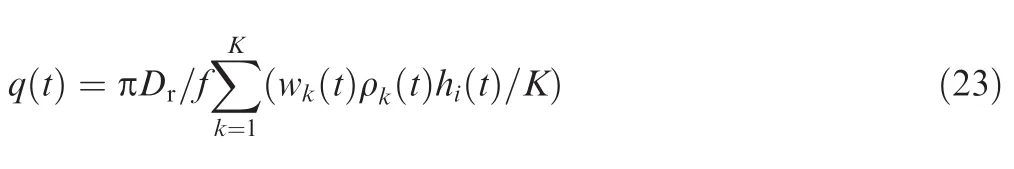
Fig.3 shows the computational domain of the finger seal leakage flow,which is related to the clearances between finger boots and the rotor.As shown in Fig.3,the coordinate axesx,y,zrepresent the circumferential,radial,and axial directions of the finger seal,respectively.The boundary conditions are set as follows.The total pressure is prescribed at inlet 1 and the static pressure at outlet 2;the static non-slip wall condition is applied to the surface of finger boot 3,while moving non-slip wall to the surface of rotor 4;rotational periodicity is set at the boundary between 5 and 6.
Considering that the fluid mass flowing through any cross sections perpendicular to the axial direction is equal,an arbitrary cross section corresponding to the leakage clearancehi(t)between a finger boot in theith finger element and the rotor is chosen to calculate the leakage of the finger seal.
Dividing the cross section intoKlayers in theydirection,the velocity offluid in thekth layer in thezdirection iswk(t),and the density of fluid is ρk(t).Therefore,the leakage of the finger seal at timetcan be expressed as
wherefis the calculation time steps of a motion period of the rotor.
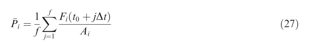
The average leakage rate of the finger seal in a motion period is defined as
2.6.2.Contact pressure between finger boots and the rotor
When a finger boot is in contact with the rotor,the contact force between the finger boot in theith finger element and the rotor at timetis stated as
whereAiis the contact area between a finger stick and the rotor;Fi(t)is the contact force between a finger boot and the rotor,which is given as follows
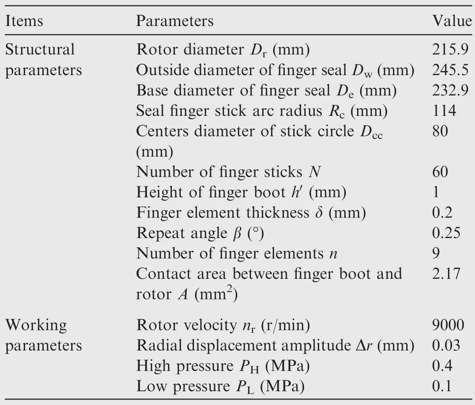
Table 1 Structural and working parameters of the finger seal.
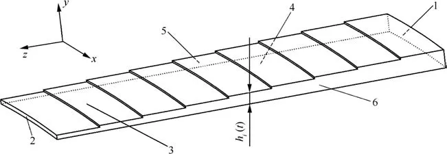
Fig.3 Computational domain of the leakage flow for the finger seal.
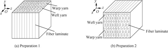
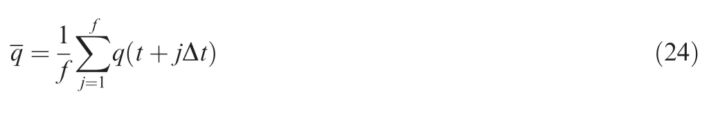
Fig.4 Schematic of the two kinds of preparation for the finger seal.
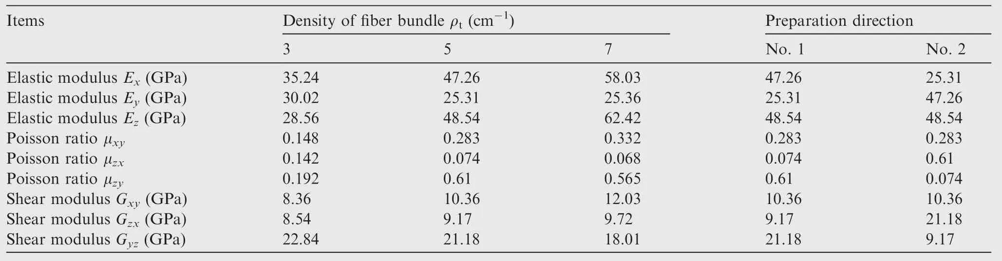
Table 2 Mechanical properties of the C/C composite.
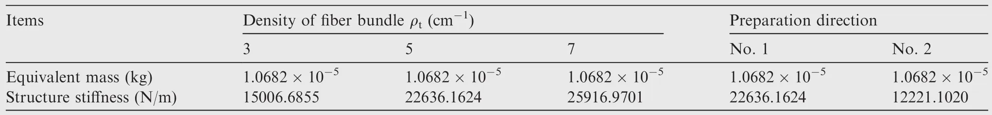
Table 3 Equivalent parameters of the 2.5D C/C composite.
Thus,the average contact pressure between a finger boot and the rotor in a motion period could be defined as
3.Results and discussion
A C/C composite finger seal with nine layers of superimposed finger elements is investigated in detail,and the effects of the structural parameters of the C/C composite on the dynamic performance of the finger seal as the rotor tilts are studied.The equivalent parameters are calculated based on the structural and working parameters of the C/C composite finger seal listed in Table 1.The contact stiffness coefficient between each finger stick and the rotor is determined by the contact state of the rotor and the finger stick.In addition,the dynamic performance of the C/C composite finger seal is obtained by solving Eqs.(1)and(2).
Precession tilt and nutation tilt of the rotor are considered in the process,and the incline angle of the rotor is limited to 0.5°.The 2.5D C/C composite with the warp yarn density being 8 stick/cm19–21is regarded as the analysis object,and only the weft yarn density is taken into account.The preparation direction of the fiber bundle for the C/C composite is divided into two types,one is the preparation direction No.1 shown in Fig.4(a)and the other is the preparation direction No.2 shown in Fig.4(b).The preparation direction No.1 is that the weft and yarn directions are consistent with the radial(yaxis)and circumferential(xaxis)directions of the finger seal,respectively,while the axial direction(zaxis)of the finger seal is perpendicular to the fiber laminate;the preparation direction No.2 is that the yarn and weft directions are consistent with the radial and circumferential directions of the finger seal,and the axial direction of the finger seal is also perpendicular to the fiber laminate.In the analysis of the influence of fiber bundle density,the preparation direction No.1 is adopted,and when analyzing the effect of the preparation direction of the fiber bundle,the weft density is 5 stick/cm.
The mechanical properties of the 2.5D C/C composite for different fiber bundle densities and different preparation directions of the fiber bundle are presented in Table 2.Table 3 shows the equivalent mass and structure stiffness of the finger seal based on the data in Tables 1 and 2.
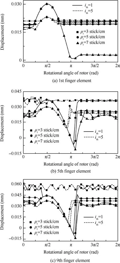
Fig.5 Displacement responses of finger sticks.
3.1.Influence of the fiber bundle density on the performance of the finger seal
Fig.5 shows the relationship between the displacement responses of finger sticks in the 1st,5th,and 9th finger elements and the fiber bundle density of the 2.5D C/C composite.It is clear that the displacement responses of finger sticks decrease with the density of the fiber bundle increasing,namely,the hysteresis of the finger seal is reduced.This is because a higher fiber bundle density increases the fiber fraction of the 2.5D C/C composite,so the overall performance of the C/C composite is enhanced,resulting in an increase in the equivalent structural stiffness of finger sticks and leading to an enhancement of the ability of finger sticks following the rotor.
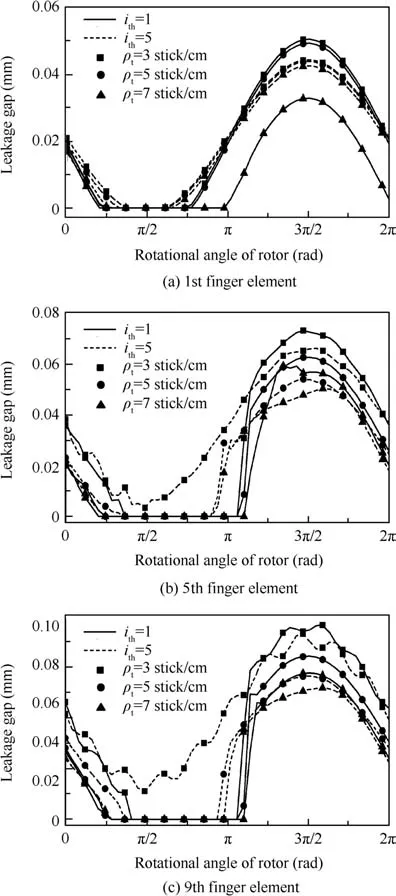
Fig.6 Leakage clearances between finger sticks and the rotor.
In Fig.5,it can be seen that the displacement responses of finger sticks in the 5th and 9th finger elements in the rotor precession tilt case are larger than those in the rotor nutation tilt case,and the reason is that the rotor tilt Δriis larger,and the tilt displacement excitation and unbalance mass displacement excitation are positively superimposed in the rotor’s precession tilt.However,the displacement responses of finger sticks in the 1st finger element are slightly different due to the coupling effect of the deformation restoring force,frictional resistance,and pressure fluid,even if the displacement excitation is smaller in the rotor nutation tilt case.
In Fig.6,the relationship between the leakage clearance and the fiber bundle density is found.It is clear that the clearance between finger boots and the rotor is smaller with the density of the fiber bundle increasing.In addition,the reason for this is seen from Fig.5.
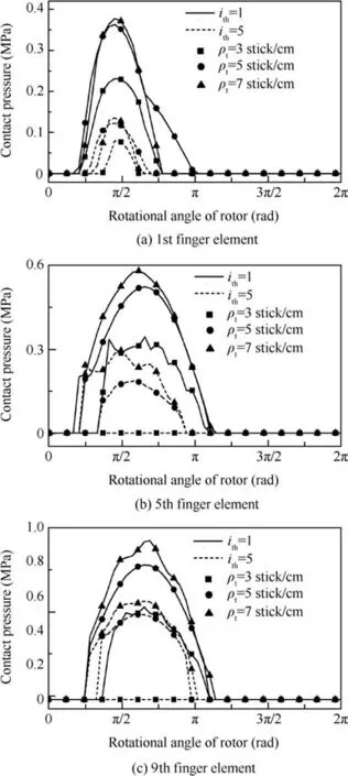
Fig.7 Contact pressure between finger sticks and the rotor.
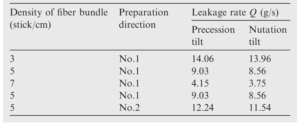
Table 4 Relationship between the leakage rate and the structural parameters of C/C composite in two kinds of tilt modes.
Fig.6 also shows that the leakage clearances between finger boots in the 5th and 9th finger elements and the rotor in the rotor precession tilt case are larger than those in the rotor nutation tilt case,which is because the larger rotor tilt in the rotor precession tilt case leads to a larger displacement excitation.However,it is worth noting that the changing trend of the clearance between finger boots in the first element and the rotor is a little different,and the reason is also related to the coupling effect of the deformation restoring force,frictional resistance,and pressure fluid.
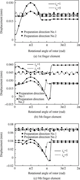
Fig.8 Displacement responses of finger sticks.
Moreover,notice that the displacement excitation acting on a finger stick in the 1st finger element in the rotor precession tilt case is the same as that acting on a finger stick in the 5th finger element in the rotor nutation tilt case,but the leakage clearance between a finger boot in the 5th finger element and the rotor is larger,and the reason is that the 5th finger element gets close to the high-pressure chamber,so the finger boot bears a higher fluid pressure.
In Fig.7,it can be seen that the relationship between the contact pressure between finger sticks and the rotor and the fiber bundle density of the 2.5D C/C composite is found.The contact pressure between finger sticks and the rotor also increases with the fiber bundle density increasing,which is because a higher fiber bundle density increases the structural stiffness of finger sticks,leading to a greater contact pressure under the same displacement excitation.Since the displacement excitation is much larger for each same finger stick in the rotor precession tilt state than that in the rotor nutation tilt state,the contact pressure between the rotor and finger sticks in each same finger element is much higher under the rotor precession tilt condition.
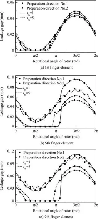
Fig.9 Leakage clearance between finger sticks and the rotor.
In Table 4,the relationship between the leakage rate and the structural parameters of the C/C composite in two kinds of tilt modes is described.It is found that the relationship between the leakage rate and the fiber bundle density is consistent with that shown in Fig.6.Since the displacement excitation is larger and the leakage clearance is ‘straight’in the rotor’s precession tilt,the leakage rate is larger compared to that in the rotor’s nutation tilt.The main reason of a smaller leakage rate in the rotor nutation tilt state is that the closed positions of the leakage clearances between finger boots in each finger element and the rotor are different,resulting in that there is a strong ‘labyrinth seal” effect in the finger seal.
3.2.Influence of the preparation direction of the fiber bundle on the performance of the finger seal
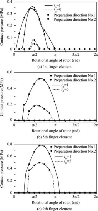
Fig.10 Contact pressure between finger sticks and the rotor.
The relationship between the displacement responses of finger sticks and the preparation direction of the fiber bundle is prescribed in Fig.8.The displacement response of a finger stick with the preparation direction No.1 is smaller,that is,the displacement to which the finger stick returns after it is separated from the rotor is larger and the hysteresis is smaller,so the corresponding leakage clearance is smaller as shown in Fig.9.On the contrary,the displacement response of a finger stick with the preparation direction No.2 is larger,so the leakage clearance is larger as shown in Fig.9.The reason for the above observations is that,for the finger seal made with the preparation direction No.1,the weft yarns bear the main radial force,and the weft yarns have a higher elastic modulus in the straight braided pattern,leading to a higher structural stiffness and a smaller hysteresis of the finger seal;for the preparation direction No.2,the warp yarns bear the main radial force,and the warp yarns have a lower elastic modulus in the sine braided pattern,therefore,a greater hysteresis is shown.
Fig.8 also shows that finger sticks in the 5th and 9th finger elements are not in contact with the rotor when the preparation No.2 is adopted.On one hand,a low equivalent structural stiffness of finger sticks in the preparation direction No.2 leads to a great hysteresis;on the other hand,the 5th and 9th finger elements close to the high-pressure chamber bear high pressure once the clearance emerges,and in addition,the clearance may be maintained.
In Fig.8,it can also be seen that the displacement responses of finger sticks in the 5th and 9th finger elements under the condition of rotor precession tilt are larger than those under the condition of rotor nutation tilt,this is because the displacement excitation in the rotor precession tilt state is larger.Due to the coupling effect of the deformation restoring force,frictionalresistance,and pressure fluid,the displacement responses of finger sticks in the first finger element are slightly different.Based on the results in Fig.8,Fig.9 shows that the leakage clearance between finger boots and the rotor is larger under the condition of rotor precession tilt.
The relationship between the contact pressure between finger sticks and the rotor and the preparation direction of the fiber bundle is presented in Fig.10.It is clear that the contact pressure between finger sticks and the rotor is higher in the preparation direction No.1,which is because the structural stiffness is higher in this preparation direction.Due to the displacement excitation is larger in rotor precession tilt,the contact pressure is higher than that in rotor nutation tilt.
In Table 4,it is noted that the leakage rate of the finger seal is smaller in the preparation direction No.1 than that in the preparation direction No.2.Moreover,in the two kinds of preparation directions,the leakage rate in rotor precession tilt is always larger than that in rotor nutation tilt.
4.Conclusions
A distributed mass equivalent dynamic model is proposed in the paper.The impacts of the structural parameters of the C/C composite and rotor tilt on the dynamic performance of the finger seal are investigated based on the proposed model.Then the main conclusions of the research are as follows.
(1)The fiber bundle density and the preparation direction of the fiber bundle of the C/C composite have an obvious influence on the performance of the finger seal.With an increase of the fiber bundle density of the C/C composite,the leakage rate is reduced,while the contact pressure increases.The leakage rate and the contact pressure are different and the changing trends are inverse corresponding to different preparation directions of the fiber bundle.Thus,a good performance of the finger seal can be acquired by controlling the fiber bundle density and the preparation direction.
(2)The effects of rotor precession tilt and rotor nutation tilt on the dynamic performance are investigated in the paper.The results show that as the incline angle keeps constant,the leakage rate of the finger seal in rotor precession tilt is larger than that in rotor nutation tilt,and it is related to that the displacement excitations acting on finger sticks are positively superimposed and the leakage clearance is ‘straight’in rotor precession tilt.Considering that rotor tilt is inevitable in the finger seal system,it is essential to reduce the incline angle as soon as possible to ensure the operating performance and the reliability of the finger seal.
(3)Considering that the contact pressure between finger sticks in each finger element and the rotor is different,a new axial finger seal can be designed based on the contact pressure between finger sticks and the rotor.For example,when the effect of rotor tilt is taken into account,since finger sticks in the 1st finger element bear low contact pressure and finger sticks in the 9th finger element bear high contact pressure,a finger seal with a good leakage rate and low wear can be obtained by increasing the structural stiffness of finger sticks in the 1st finger element and decreasing the structural stiffness of finger sticks in the 9th finger element.
Acknowledgements
This study was co-supported by the National Natural Science Foundation of China(No.51575445)and the Natural Science Foundation of Shaanxi Province of China(No.2014JM7266).
1.Delgado IR,Proctor MP.Continued investigation of leakage and power loss test results for competing turbine engine seals.Reston:AIAA;2006.Report No.:AIAA-2006-4754.
2.Proctor MP,Delgado IR.Leakage and power loss test results for competing turbine engine seals.In:ASME turbo expo 2004 power for land,sea,and air;2004 Jun 14–17;Vienna,Austria;2004.p.441–51.
3.Proctor MP,Arun K,Delgado IR.High-speed,high-temperature finger seal test result.J Propuls Power2004;20(2):312–8.
4.Arora GK,Proctor MP,Steinetz BM,Delgado IR.Pressure balanced,low hysteresis,finger seal test results.Reston:AIAA;1999.Report No.:AIAA-1999-2686.
5.Braun MJ,Pierson HM,Deng DF,Choy FK,Proctor MP,Steinetz BM.Structure and dynamic consideration towards the design of padded finger seal.Reston:AIAA;2003.Report No.:AIAA-2003-4698.
6.Braun MJ,Pierson HM,Deng D.Thermofluids considerations and the dynamic behavior of a finger seal assembly.Tribol Trans2005;48(4):531–47.
7.Marie H.Dynamic simulation of finger seal-rotor interaction using variable dynamic coefficients.Reston:AIAA;2006.Report No.:AIAA-2006-4931.
8.Su H,Chen GD.Dynamic behavior analysis of finger seal based on equivalent dynamic model.Chin J Mech Eng2010;23(5):590–9.
9.Chen GD,Lu F,Yu QP,Su H.Dynamic analysis of finger seal using equivalent model based on distributed mass method.Proc IMechE Part C:J Mech Eng Sci2014;288(16):2992–3005.
10.Du KB,Li YJ,Suo SF,Wang YM.Dynamic leakage analysis of noncontacting finger seals based on dynamic model.J Eng Gas Turb Power2015;137(9):1–7.
11.Du KB,Li YJ,Suo SF,Wang YM.Semi-analytical dynamic analysis of noncontacting finger seals.Int J Struct Stability and Dynamics2015;15(4):1–13.
12.Lu F,Chen GD,Su H,Wang LN.Analysis of dynamic performance for 2.5D carbon-carbon composite finger seals.Acta Aeronautica et Astronautica Sinica2013;34:2616–25[Chinese].
13.Chen GD,Wang LN,Yu QP,Su H.Dynamic analysis of C/C composite finger seal.Chin J Aeronaut2014;27(3):745–58.
14.Hazel M.A study of non-contacting passive-adaptive turbine finger seal performance[dissertation].Akron:The University of Akron;2005.
15.Bhushan B.Introduction to tribology.2nd ed.Hoboken:Wiley;2013.p.122.
16.Polycarpou AA,Etsion I.Analytical approximations in modeling contacting rough surfaces.ASME J Tribol1999;121(2):234–9.
17.Shi X,Polycarpou AA.Measurement and modeling of normal contact stiffness and contact damping at the meso scale.J Vibr Acoust2005;127(52):52–60.
18.Zhao B,Zhang S,Man J,Zhang Q,Chen Y.A modified normal contact stiffness model considering effect of surface topography.Proc IMechE Part J:J Eng Tribol2015;299(6):677–88.
19.Su H,Wang L.Study on 2.5D C/C composite finger seal integrate optimization combined with microstructural parameters of material and macro geometry of finger seal.Proc IMechE Part C:J Mechanical Engineering Science.[in press].
20.Pochiraju K,Chou TW.Three-dimensionally woven and braided composites.I:a model for anisotropic stiffness prediction.Polym Compos1999;20(4):565–80.
21.Zheng J,Wen WD,Cui HT,Gao JH.Original yield of 2.5D woven composites loaded in weft.Acta Aeronautica et Astronautica Sinica2009;30(2):254–8[Chinese].
15 July 2016;revised 14 September 2016;accepted 9 October 2016
Available online 21 December 2016
*Corresponding author.
E-mailaddresses:zhaohailin@mail.nwpu.edu.cn (H.ZHAO),gdchen@nwpu.edu.cn (G. CHEN), wangxiweigood@163.com(L.WANG),huasu@nwpu.edu.cn(H.SU),lufei@mail.nwpu.edu.cn(F.LU).
Peer review under responsibility of Editorial Committee of CJA.
Production and hosting by Elsevier
http://dx.doi.org/10.1016/j.cja.2016.11.002
1000-9361©2016 Chinese Society of Aeronautics and Astronautics.Production and hosting by Elsevier Ltd.
This is an open access article under the CC BY-NC-ND license(http://creativecommons.org/licenses/by-nc-nd/4.0/).
Aero-engine;
C/C composite;
Dynamic performance;
Finger seal;
Nutation tilt;
Precession tilt
杂志排行

CHINESE JOURNAL OF AERONAUTICS的其它文章
- Wake structure and similar behavior of wake profiles downstream of a plunging airfoil
- Self-sustained oscillation for compressible cylindrical cavity flows
- Numerical studies of static aeroelastic effects on grid fin aerodynamic performances
- A new vortex sheet model for simulating aircraft wake vortex evolution
- Linear stability analysis of interactions between mixing layer and boundary layer flows
- Aerodynamic multi-objective integrated optimization based on principal component analysis