Approach and landing guidance design for reusable launch vehicle using multiple sliding surfaces technique
2017-11-20XingdongLIUFengdiZHANGZhenLIYoZHAO
Xingdong LIU,Fengdi ZHANG,Zhen LI,*,Yo ZHAO
aSchool of Automation,Beijing Institute of Technology,Beijing 100081,China
bNational Key Laboratory of Complex System Intelligent Control and Decision,Beijing Institute of Technology,Beijing 100081,China
cChina Academy of Launch Vehicle Technology,Beijing 100076,China
Approach and landing guidance design for reusable launch vehicle using multiple sliding surfaces technique
Xiangdong LIUa,b,Fengdi ZHANGa,Zhen LIa,b,*,Yao ZHAOc
aSchool of Automation,Beijing Institute of Technology,Beijing 100081,China
bNational Key Laboratory of Complex System Intelligent Control and Decision,Beijing Institute of Technology,Beijing 100081,China
cChina Academy of Launch Vehicle Technology,Beijing 100076,China
An autonomous approach and landing(Aamp;L)guidance law is presented in this paper for landing an unpowered reusable launch vehicle(RLV)at the designated runway touchdown.Considering the full nonlinear point-mass dynamics,a guidance scheme is developed in threedimensional space.In order to guarantee a successful Aamp;L movement,the multiple sliding surfaces guidance(MSSG)technique is applied to derive the closed-loop guidance law,which stems from higher order sliding mode control theory and has advantage in the finite time reaching property.The global stability of the proposed guidance approach is proved by the Lyapunov-based method.The designed guidance law can generate new trajectories on-line without any specific requirement on off-line analysis except for the information on the boundary conditions of the Aamp;L phase and instantaneous states of the RLV.Therefore,the designed guidance law is flexible enough to target different touchdown points on the runway and is capable of dealing with large initial condition errors resulted from the previous flight phase.Finally,simulation results show the effectiveness of the proposed guidance law in different scenarios.
©2017 Chinese Society of Aeronautics and Astronautics.Production and hosting by Elsevier Ltd.This is an open access article under the CC BY-NC-NDlicense(http://creativecommons.org/licenses/by-nc-nd/4.0/).
1.Introduction
In recent decades,there is an increasing demand for the improvement of the reliability,safety and low-cost of the reusable launch vehicle(RLV)during the reentry process.The approach and landing(Aamp;L)phase,as the terminal phase of the reentry flight,is responsible for directing the RLV from the terminal area energy management(TAEM)phase to runway touchdown.1In the reentry phase,the extreme working conditions constantly experienced,such as the poor vehicle performance,aerosur face failures and aerodynamic perturbation,so that it is indispensable for the RLV to evaluate the current performance on board as well as re-target an alternative landing site if necessary.2As a consequence,the significant deviation from the desired trajectory commonly encountered at the approach and landing interface(ALI),under the circumstance of which the RLV can no longer follow a predesigned trajectory to perform a success full anding movement.Therefore,it is of necessary importance to develop advanced guidance technologies to generate feasible trajectories onboard without relying on the predesigned reference trajectories.3
Since the Aamp;L phase plays a crucial role in the safety of the vehicle,many focuses have been put on the Aamp;L guidance problem.A trajectory-planning based Aamp;L guidance strategy was proposed,1where the whole trajectory was divided into several segments defined by a small set of geometric parameters.Through combining an iterative approach and a backward trajectory propagation scheme,a feasible reference trajectory that brought the RLV from its current state to a desired landing condition was obtained and both open-loop and closed-loop analysis were provided.This method was able to re-compute new reference Aamp;L profiles even in the presence of severe wind,aerodynamic uncertainties as well as trajectory dispersions.Moreover,this approach was further extended to deal with a RLV with limited normal acceleration capabilities.4The design goal was achieved by minimizing the maximal load factor during the Aamp;L phase.To ensure a better landing movement,a Mnmdanifuzzy PD controller was developed for the Aamp;L phase.5The reliability and robustness of the controller was verified via Monte Carlo simulations considering various kinds of disturbances.The fault tolerant capability of an aircraft was further enhanced by the controllers proposed.6,7An Optimum-Path-To-Go(OPTG)algorithm,characterized by on-line trajectory reshaping and re-targeting capabilities with a huge number of off-line trajectories generated in advance was presented to deal with the Aamp;L guidance problem.8–10Under given current states and certain vehicle parameters,the on-line trajectory command generation was thus available.Moreover,the OPTG was employed to cope with the control surface errors between the entry phase and the TAEM phase.11Besides,the capability to re-target at more suitable alternative landing sites was studied.12
Sliding mode control(SMC)has been widely used in the guidance law design due to its strong robustness in nature.A novel concept of the sliding mode terminal guidance(SMTG)was proposed to solve the Aamp;L guidance problem,in which the finite-time-reaching phase of the sliding mode control was utilized and the desired terminal conditions could be achieved at the final instant.13Since the associated guidance command relied only on the initial and final conditions of the Aamp;L phase,this strategy prevented itself from off-line requirements and was able to generate new trajectories online.A novel finite horizon suboptimal controller based on state dependent Riccati equation(SDRE)was discussed.14To solve the differential Riccati equation without backward integration,an approximate method was developed.The proposed controller was then employed to solve the on-line path-planning problem for the Aamp;L phase,which presented robust under different initial conditions with small computational burdens.
It should be noted that the desired objective of the Aamp;L phase is to softly land the RLV at the predetermined runway,and the final flight path angle should reach near-zero at touchdown in order to achieve a minimal vertical velocity.In addition,the visual reference should be preserved with respect to the center line of the runway before the RLV approaches the runway surface to guarantee a successful touchdown movement.Targeted at all these requirements,a nonlinear closed form three-dimensional(3D)landing guidance law is developed in this paper.Based on the multiple sliding surface technique(MSST),the designed guidance law is adopted to address the problem of successfully landing an RLV even in the presence of large initial condition errors.The guidance logic is developed independently in different channels,i.e.,the lateral channel and longitudinal channel.In each channel,the first sliding mode surface is specially designed according to the terminal constraints.Both the sliding mode function and its derivative to zero at the final instant are simultaneously achieved.By introducing a second sliding mode function,a backstepping approach is utilized to meet such requirements.Thus,the second sliding mode surface is concatenated to the first sliding mode surface:as long as the second sliding mode surface is established at a finite time,which is generally smaller than the total flight time,the first sliding mode will reach and then stay on its desired trajectory with the desired terminal system states.The finite time establishment of the second sliding mode is guaranteed by the Lyapunov stability theory.Due to its simple form and less information demand,the proposed guidance law is specifically suitable for the onboard implementation.Besides,the closed-loop dynamics are capable of counteracting the external disturbances by virtue of the strong robustness of SMC.
The rest of the paper is organized as follows.In Section 2,the Aamp;L guidance problem of the RLV is formulated and the associated equations of motion are described.In Section 3,the MSST based guidance logics is analyzed in detail in the lateral channel and longitudinal channel,respectively.Section 4 performs the simulations to validate the effectiveness of the proposed guidance scheme under various conditions.Finally,Section 5 concludes this paper with the discussion on future work.
2.Motion and problem formulation
This section gives the dynamic model for the RLV during the Aamp;L phase.For the sake of clarity,a diagram of the Aamp;L phase in the inertial coordinate frame is presented in Fig.1.
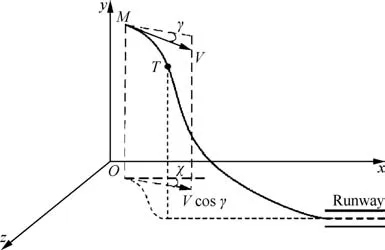
Fig.1 Diagram of the Aamp;L phase.
The Aamp;L phase can be divided into two phases.The first phase is from the ALI to the transition pointT,where any possible lateral errors(i.e.initial pointing error and initial position error)would be corrected.The second phase is from the pointTonwards,where the velocity vector of the RLV stays in the pitch plane determined by the runway centerline.The responsibility of the second phase is to bring the RLV from its current states to a desirable touchdown movement.
In Fig.1,the RLV is represented byM;the flight path angle and heading angle are denoted by γ and χ,respectively;the velocity is defined asV.It should be noted that the initial lateral errors have been corrected at the transition pointTand the trajectory will stay in the pitch plane afterwards.x,y,zare the position coordinates in the reference frame.
Considering a flat-Earth model,the three-degree-offreedom(3DOF)point-mass dynamics of the RLV is given by Eqs.(1)–(6).
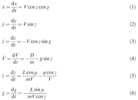
wheretis the time variable;mrepresents the mass of RLV;gis acceleration of gravity;μ is the bank angle.The aerodynamic lift and drag are defined in the usual manner as

whereq=is the dynamic pressure determined by the air density ρ and the velocityV;Srepresents the reference area of the vehicle;the lift and drag coefficients are defined asCLandCD,respectively.
The equations of motion Eqs.(1)–(6)take timetas the independent variable.However,the flight time of the Aamp;L phase is normally not the key issue of concern.The objective of this phase is to land the RLV with the least possible vertical velocity at the predetermined position.Considering that the downrange is strictly monotone increasing during the Aamp;L phase,the downrange is selected as the new independent variable instead of time.Therefore,the system model can be changed to the following equations.

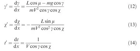
where the prime superscript indicates that the differentiation is taken with respect to the downrange.This new model is used to develop the Aamp;L guidance law detailed in the next section.It is worth noticing that the desired guidance commands are the angle of attack α and the bank angle μ.For convenience,however,the derivative of the flight path angle γ'and the derivative of the heading angle χ'are used as the auxiliary control efforts.The desired guidance commands can be easily obtained from the auxiliary control efforts.
3.Nonlinear approach and landing guidance law
In this section,a 3D nonlinear closed-loop guidance scheme based on multiple sliding surfaces guidance(MSSG)is developed for the Aamp;L phase.The objective is to design a robust landing-guidance law,able to achieve a successful touchdown at the predetermined landing site in the presence of initial condition errors.The lateral guidance logic is firstly described,and followed by the longitudinal guidance logic development.
3.1.Lateral guidance logic
As described in Section 2,the lateral errors of the RLV should be removed at the pointT.For the sake of description,thexaxis is defined to be parallel to the runway.The inertial coordinate ofTand the touchdown point are assumed to be(xt,yt,zt)and(xf,yf,zf),respectively.The desired heading angle χtshould be set to zero in this way.Therefore,the design goal for the lateral guidance logic can be summarized as follows.First,both the crossrange and heading angle of the RLV should be driven to their desired values as the downrange goes toxt,i.e.,(z,χ)→ (zt,χt)as(x→xt).Next,they should maintain their current states until the touchdown moment,i.e.,(z,χ)≡ (zt,χt)for(xt≤x≤xf).
It can be seen from Eq.(10)thatz'only relates to χ,implying that there exists a one-to-one correspondence betweenz'and χ.Therefore,the objective of enforcing χ to χtcan be equivalently achieved by drivingz'towhere=-tanχt=0.Motivated by this concept,the first sliding surface is designed as
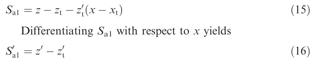
It can be easily observed that if bothSa1andS'a1are driven to zero atx=xtand maintained thereafter,the desired objectives can be satisfied.
In order to make the first appearance of the control effort χ',the second derivatives ofSa1is taken and we get
It can be revealed from Eq.(17)that the sliding surfaceSa1possesses a relative degree of two.Hence,it belongs to a higher-order sliding mode control(HOSMC)category.15Since the desired objective requires to be fulfilled at a finite downrangexr,it can be solved using the finite-time control methods.Levant proposed a control strategy,where two-sliding homogeneous control could rotate around the sliding surface,zeroing it out in finite time.16The other popular finite-time control method is the terminal sliding mode control(TSMC)algorithm,17,18in which a terminal sliding surface was designed and the finite-time convergence was guaranteed by keeping the system states on the specified sliding surface.These methods,though effective enough,still cannot set the time convergence in advance.Thus,they are not suitable to develop the guidance law here.Harl and Balakrishnan13developed a new finite-time control approach for reentry terminal guidance problems.This method,which stems from the underlying fundamentals of sliding mode control,possessed the capability of enforcing both the sliding mode function and its derivative to zero at a designated finite time.However,the control action terminated as long as the sliding surface was reached.For the lateral guidance problem,the control process cannot be suspended fromx=xtafterwards since the RLV has not yet reached the touchdown point.The crossrangezand the heading angle χ,which have already been driven to their desired values,should be consistently maintained on their current states thereafter.
In the following discussion,the MSSG based guidance law will be detailed.The associated control algorithm is built on the basic principles of the sliding mode control.13
Using Eqs.(15)and(16),the second sliding surface is designed as follows.
Lemma 1.Suppose thatx0<xk<xtand λ>1 is a constant.IfSa2maintains zero fromxkonwards,bothSa1andwill go to zero exactly atx=xt.
Proof.FromSa2=0,we have
Eq.(19)can be rewritten as
SinceSa2≡0 forxk≤x≤xt,Eq.(20)can be formally integrated from(xk;Sa1(xk))to(x;Sa1(x)).With some algebra manipulation,it yields
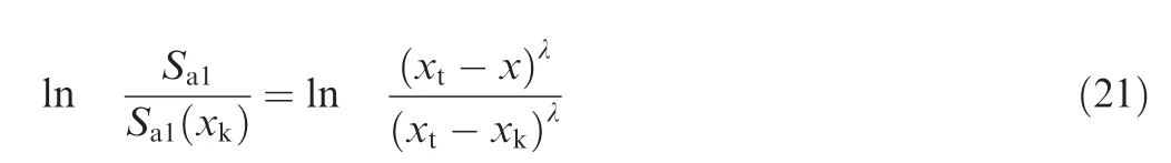
Taking the exponential of both sides,the following solution can be obtained
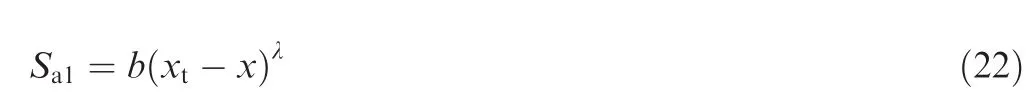
whereb=is a constant.Then,the derivative of the sliding surface with respect toxcan also be expressed as

From an inspection of Eqs.(22)and(23),the first sliding surface together with its derivative will reach zero forx=xtas long as λ is larger than one.
Lemma 1 defines a reasonable relationship betweenSa1andi.e.,Eq.(19).At the instant when the Aamp;L phase is initiated,while the states of the RLV are generally undetermined beforehand such that the relationship is not satisfied,i.e.,Sa2≠0.As a consequence,a proper controller needs to be further developed to drive and maintain the second sliding surface to zero. □
Theorem 1.Consider the lateral guidance system characterized by Eqs.(10)and(17),and choose the guidance command as Eq.(24)
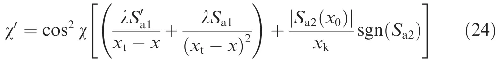
The crossrangezand the heading angle χ will both go to their desired values asx→xt.
Proof.Define the following Lyapunov candidate:

The derivative ofV1with respect to the downrange can be calculated as
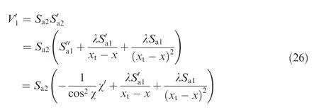
Then,substituting the guidance command Eq.(24)into Eq.(26),yields
According to the Lyapunov theory,the system is globally stable. Further, from Eq. (27), we havethe rate of approaching the second sliding surface.Consequently,Sa2would reach zero at the downrange ofxkand maintain thereafter.Associating this result with Lemma 1,it can be concluded that bothSa1andwould go to zero asx→xt.Whenxconverges toxton the second sliding surface,i.e.,Sa2=0,Sa1andwill accordingly become zero.Therefore,it can be concluded from Eqs.(15)and(16)thatzand χ converges to their expected values,respectively. □
As pointed out by Harl and Balakrishnan,13the guidance scheme cannot keep the system states on the first sliding surface after it is reached.This conclusion is obviously straightforward from Eqs.(22)and(23).As previously discussed,however,the crossrangezand the heading angle χ should be maintained on their desired values forxt≤x≤xf.This problem can be solved as follows.
Assuming that Δxis a positive constant with very small magnitude.Forxt-Δx≤x≤xf,the second sliding surface is changed into the following format:
It should be noted that Eq.(28)is obtained by substitutingx=xt-Δxinto Eq.(18).Therefore,the sliding surfaceSa2is continuous atx=xt-Δx.Considering Eq.(28),the following result can be derived by settingSa2=0


wherek1=Sa1(xt-Δx)andk2=are both constants.The derivative ofSa1can also be obtained as As shown in the above two equations,Sa1andare continuous atx=xt-Δxand their magnitudes are monotonically decreasing forx≥xt-Δx.Therefore,bothSa1andare limited within a very small vicinity of the origin forxt-Δx≤x≤xfso that bothzand χ can be constrained to their desired values.
Correspondingly,the lateralguidance command forxt-Δx≤x≤xfcan be derived using Lyapunov Second Method when consideringV2=as Lyapunov candidate function.DifferentiatingV2with respect tox,yields
The control effort is chosen with the following form:

Substituting it into Eq.(31),yields=-k3|Sa2|.Obviously,as long ask3>0,is negative definite and thus the system is global stable.For simplicity,the value ofk3is selected as
As a result,the final expression for the lateral guidance command is given as follows:

3.2.Longitudinal guidance logic
The designed objective of the longitudinal guidance logic is to guarantee a soft landing of the RLV at the touchdown point.It is assumed that the flight path angle and the vertical velocity at the touchdown are γfandVyf,respectively.It is obvious that γfshould be pulled up to zero to ensure a minimal magnitude ofVyf.However,there is no need to stringently constrainVyfto zero,and a small magnitude ofVyfis still acceptable for the
RLV at touchdown.Based on such requirements,γfis chosen to be a negative constant with small magnitude,and the first sliding surface is constructed as


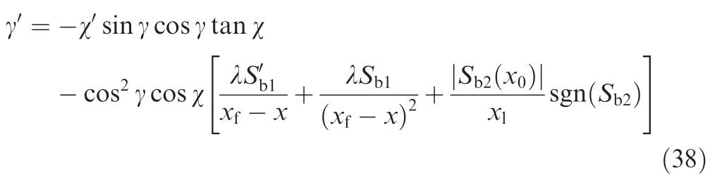
Since the lateral guidance logic is able to guarantee χ = χtforxt≤x≤xf,the conclusion can be apparently made for the altitudeyto be driven toyfwith a small magnitude of the flight path angle as long as bothSb1andare enforced to zero asx→xf.The second derivative ofSb1is taken to make the appearance of the control effort as
It should be noted that χ'is provided by the lateral guidance logic and thus the control command for the longitudinal guidance is the derivative of the flight path angle γ'.
Therefore,a second sliding surface is designed as

Theorem 2.For the longitudinal guidance system described by Eqs.(9)and(36),ifx0<xl<xf,the MSSG based algorithm of Eq.(38)can direct the RLV to a desirable touchdown movement,i.e.,y→yfand γ→ γfasx→xf.
Proof.The proof is similar to that of Theorem 1 by choosingV3=as the Lyapunov function.□
Remark 1.It can be observed from Eq.(38)that the termxf→xappears in the denominator of the associated control law,which may give rise to a singular problem whenx=xf.However,if the value of λ is chosen larger than two,this problem can be avoided.The reason is detailed as follows.By applying the control law Eq.(38),the sliding surfaceSb2can be driven to zero atx=xl.From this point onwards,the trajectories ofSb1andwill have the following form,
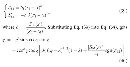
It can be easily observed from the above equation that the singularity problem is overcome as long as λ > 2.
Remark 2.The key difference between the longitudinal guidance process and the lateral guidance process is that the former is suspended when the first associated sliding surface and its derivative reach zero while the latter still continues thereafter.In fact,the proposed control laws have shown their potential in solving finite-time control problems.On the one hand,the longitudinal control scheme is suitable for dealing with control problems,in which a goal to be achieved in a given finite time is required.On the other hand,for tracking problems,in which the state errors are driven to zero at a designated finite time and maintained.Thereafter,it can be tackled using the lateral control algorithm.
3.3.Angle of attack and bank angle commands
The previously developed lateral and longitudinal guidance commands are based on the system model described by Eqs.(9)–(14).Note that the guidance commands can also be transformed into the time domain according to the following transformation.
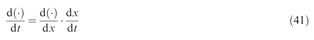
Then,the guidance commands are time-dependent and have the following form as

Therefore,Eqs.(1)–(6)are used for simulation as the system model.In the sequel,the angle of attack and bank angle commands will be derived.
Using Eqs.(5)and(6),the bank angle command can be obtained by
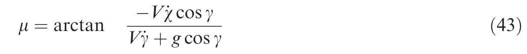
Then,according to Eqs.(5)and(7),the commanded lift coefficientCLccan be derived by
As a result,the angle of attack command can be obtained by numerical methods such as Newton’s method and linear interpolation.
4.Simulation results
In this section,the implementation of the proposed guidance scheme is studied through numerical simulations.The RLV model used for simulations is taken from.14The lift and drag coefficients are determined by the following equations:
where α is the angle of the attack;CL0andCD0are initial values of the lift and drag coefficients;KIis the gain for drag coefficient.
The values of the RLV parameters are detailed in Table 1.14The unites ofSandmare ft2(1 ft=0.3048 m)and slug(1 slug=14.5939 kg),respectively.In addition,the atmospheric properties used in this study are based on the 1976 U.S.Standard Atmosphere.19
Furthermore,the parametersxt,xk,xlin the numerical simulations are formulated as follows:
Except for the RLV parameters above,other parameters for the simulation are listed in Table 2,respectively.The allowable angle of attack is bounded between-10°and 30°.
The switching function sgn in the control law can cause chattering.In order to eliminate the chattering problems,this paper introduces the technology of boundary layer,
The smaller the boundary layer thickness is,the higher the control accuracy will be.But it is too small to overcome the chattering problems.Hence,the boundary is weighed down,i.e.,a=0.001.
To verify the validity of the designed multiple sliding surface guidance technique,three cases simulations are taken into consideration.
Case 1.Transform the initial altitude and initial crossrange.
This case is used to evaluate the robustness of the proposed guidance law in different initial altitudes and initial crossranges,and the corresponding simulation results are shown in Fig.2.The subscript Ini represents the initial value of the corresponding parameter.
As can be seen from Fig.2(a)–(f),no matter how to transform the initial height and the initial crossrange,the designed MSSG technology can always form new guidance instruction so as to make the RLV a soft landing.With the increase of the crossrange,the heading angle χ and bank angle μ amplitude also increases during the transition pointT.Finally,the heading angle χ and bank angle μ changes to 0.It is shown that the controller has good robustness.For different initial altitudes and initial crossranges,the flight path angle γ can converge to the desired value at the end of the simulation.Fig.2(g)and(h)present a discontinuous phenomenon.This phenomenon occurs when two sliding functionsSa2andSb2converge to 0,causing the slope discontinuity and resulting in the jump in control terms.However,the guidance law is still valid.
Case 2.Transform the initial flight path angle γ and initial heading angle χ.

Table 1 Model parameters.

Table 2 Simulation parameters.

Fig.2 Simulation results in Case 1.
In this case,the initial flight path angle γ and initial heading angle χ are adjusted to evaluate the robustness of the proposed guidance law,and the corresponding simulation results are shown in Fig.3.
It can be observed from Fig.3(b)–(d)that although there are obvious pull actions,different initial flight path angle γ and initial heading angle χ can be controlled towards 0.As can be seen from Fig.3(a)–(c),for different initial flight path angle γ,RLV can achieve the soft landing with a flight path angle of-0.5°at the altitude of 0°and downrange of 20000 ft in position.Fig.3(e)and(f)further show that the guidance instruction is smooth and beneficial to attitude tracking system.
Case 3.Transform the control parameter λ
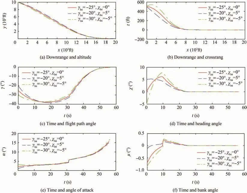
Fig.3 Simulation results in Case 2.
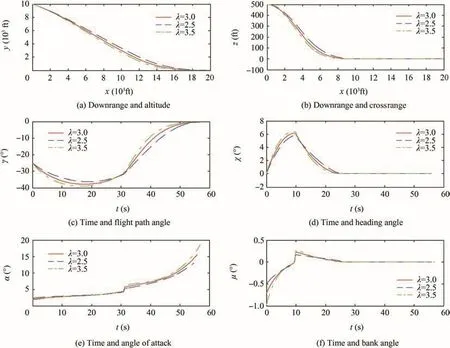
Fig.4 Simulation results in Case 3.
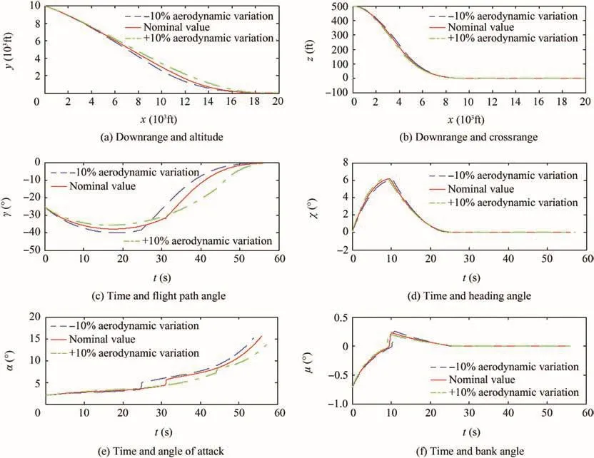
Fig.5 Simulation results in Case 4.
To evaluate the efficiency of the control parameter for the guidance law,the control parameter λ is accordingly changed in this case,and the corresponding simulation results are shown in Fig.4(a)–(f)The simulation results are shown from Fig.4(a)–(d)after changing the guidance parameter λ.Based on Eqs.(10),(15),(16),(22),(23),the following equation can be obtained,At the transition pointT,zt=0,=-tanχt=0,soz=b(xt-x)λ,z'=-bλ(xt-x)λ-1.With the increase of λ,zand χ quickly approach 0.Based on Eqs.(9),(34),(35),(39),the following equations can be gotten,After the transition pointT,the heading angle is changed to 0,Eq.(9)is simplified toy'=tanγ.It is obvious that,the greater λ is,the fasteryand γ tend to get close to the desired value.It can be seen from Fig.4(e)and(f)that with the increase of λ,the angle of attack and the bank angle amplitude rise as well.
From the above three cases of simulation results,the designed guidance law presents the strong robustness against initial parameters change.By varying the initial position,the RLV still can accurately land on the intended orbit.Transforming different angles,the RLV can produce a visible landing trajectory by means of multiple sliding surface technology,so as to complete a safe landing.
Case 4.Simulation with aerodynamic deviations
This example verifies the robustness of the guidance law against the atmospheric density perturbations.The corresponding simulation results are shown in Fig.5.As seen from the figures,regardless of the atmospheric density forward or lateral pull side,the proposed guidance law can guarantee smooth guidance commands so that the aircraft can be effectively controlled to land in the desired attitude.Therefore,the simulation results validate the robustness of the system even under the atmospheric density perturbation by the proposed guidance law.
5.Conclusions
In this paper,the closed-loop guidance control law is developed by introducing multiple sliding surface to ensure a successful Aamp;L movement.With the proposed guidance control law,the RLV in the autonomous approach and landing phase is capable of performing flight according to the predetermined orbit.Besides,the flight path angle in the final phase is also pulled up to be close to 0 for a soft landing so as to achieve the smaller vertical velocity.This guidance law has remarkable advantage in requiring none of the off-line analysis and verification with a new trajectory online.The simulation results show the feasibility of this guidance method in threedimensional space of the trajectory planning.
Acknowledgements
This study was co-supported by the National Natural Science Foundation of China(Nos.51407011,11372034,11572035).
1.Kluever CA.Unpowered approach and landing guidance using trajectory planning.J Guid,Control,Dynam2004;27(6):967–74.
2.Hanson JM,Coughlin DJ,Dukeman GA,Mulqueen JA,McCarter JW.Ascent,transition,entry,and abort guidance algorithm design for the X-33 vehicle.Reston:AIAA;1997.Report No.:AIAA-1997-4409.
3.Hanson JM.A plan for advanced guidance and control technology for 2nd generation reusable launch vehicles.Reston:AIAA;2002.Report No.:AIAA-2002-4557.
4.Kluever CA.Unpowered approach and landing guidance with normal acceleration limitations.J Guid,Control,Dynam2007;30(3):882–5.
5.Min C,Lee D,Cho K,Jo S,Yang J,Lee W.Control of approach and landing phase for reentry vehicle using fuzzy logic.Aerosp Sci Technol2011;15(4):269–82.
6.Menon PK,Vaddi SS,Sengupta P.Robust landin-guidance law for impaired aircraft.J Guid,Control,Dynam2012;35(6):1865–77.
7.Pashilkar AA,Sundararajan N,Saratchandran P.A fault-tolerant neural aided controller for aircraft auto-landing.Aerosp Sci Technol2006;10(1):49–61.
8.Schierman J,Ward D,Monaco J,Hull J.A reconfigurable guidance approach for reusable launch vehicles.Reston:AIAA;2001.Report No.:AIAA-2001-4429.
9.Schierman J,Hull J,Ward D.Adaptive guidance with trajectory reshaping for reusable launch vehicles.Reston:AIAA;2002.Report No.:AIAA-2002-4458.
10.Schierman J,Hull J,Ward D.Online trajectory command reshaping for reusable launch vehicles.Reston:AIAA;2003.Report No.:AIAA-2003-5439.
11.Schierman J,Ward D,Hull J,Gahndi N,Oppenheimer M,Doman D.Integrated adaptive guidance and control for re-entry vehicles with flight-test results.J Guid,Control,Dynam2004;27(6):975–88.
12.Schierman J,Hull J.In-flight entry trajectory optimization for reusable launch vehicles.Reston:AIAA;2005.Report No.:AIAA-2005-6434.
13.Harl N,Balakrishnan SN.Reentry terminal guidance through sliding mode control.J Guid,Control,Dynam2010;33(1):186–99.
14.Heydari A,Balakrishnan SN.Path planning using a novel finite horizon suboptimal controller.J Guid,Control,Dynam2013;36(4):1210–4.
15.Levant A.Higher-order sliding modes,differentiation and output feedback control.Int J Control2003;76(9–10):924–41.
16.Levant A.Construction principles of 2-sliding mode design.Autom2007;43(4):576–86.
17.Wu Y,Yu X,Man Z.Terminal sliding mode control design for uncertain dynamic systems.Syst Control Lett1998;34(5):281–7.
18.Liu X,Yu Y,Li Z,Iu HHC.PolytopicH∞filter design and relaxation for nonlinear systems via tensor product technique.Signal Process2016;127:191–205.
19.COESA.U.S.standard atmosphere.Washington,D.C.:NASA;1976.Report No.:NASA TR R-459.
29 February 2016;revised 13 May 2016;accepted 13 December 2016
Available online 20 June 2017
*Corresponding author at:School of Automation,Beijing Institute of Technology,Beijing 100081,China.
E-mail address:zhenli@bit.edu.cn(Z.LI).
Peer review under responsibility of Editorial Committee of CJA.
Production and hosting by Elsevier
http://dx.doi.org/10.1016/j.cja.2017.06.008
1000-9361©2017 Chinese Society of Aeronautics and Astronautics.Production and hosting by Elsevier Ltd.
This is an open access article under the CC BY-NC-ND license(http://creativecommons.org/licenses/by-nc-nd/4.0/).
Finite time control;
Landing guidance;
Lyapunov stability;
Reusable launch vehicle;
Sliding mode control
杂志排行
CHINESE JOURNAL OF AERONAUTICS的其它文章
- Wake structure and similar behavior of wake profiles downstream of a plunging airfoil
- Self-sustained oscillation for compressible cylindrical cavity flows
- Numerical studies of static aeroelastic effects on grid fin aerodynamic performances
- A new vortex sheet model for simulating aircraft wake vortex evolution
- Linear stability analysis of interactions between mixing layer and boundary layer flows
- Aerodynamic multi-objective integrated optimization based on principal component analysis