Research on a six-phase permanent magnet synchronous motor system at dual-redundant and fault tolerant modes in aviation application
2017-11-20XiaolinKUANGHongGUOJinquanXUTongZHOU
Xiaolin KUANG,Hong GUO,Jinquan XU,Tong ZHOU
School of Automation Science and Electrical Engineering,Beihang University,Beijing 100083,China
Research on a six-phase permanent magnet synchronous motor system at dual-redundant and fault tolerant modes in aviation application
Xiaolin KUANG,Hong GUO,Jinquan XU*,Tong ZHOU
School of Automation Science and Electrical Engineering,Beihang University,Beijing 100083,China
With the development of more/all electrical aircraft technology,an electro-mechanical actuator(EMA)is more and more used in an aircraft actuation system.The motor system,as the crucial part of an EMA,usually adopts the redundancy technology or fault tolerance technology to improve the reliability.To compare the performances of these two motor systems,a 10-pole/12-slot six-phase permanent magnet synchronous motor(PMSM)is designed with the concentrated single-layer winding,which is able to operate at dual-redundant and fault tolerant modes.Furthermore,the position servo performances of the six-phase PMSM at dual-redundant and fault tolerant modes are analyzed,including the normal and fault conditions.In addition,a variable structure proportional-integral-derivative(PID)control strategy is proposed to solve the performance degradation problem caused by phase current saturation.Simulation and experimental results show that the fault tolerant PMSM has a better position servo performance than the dual-redundant PMSM,and the variable structure PID control strategy is able to improve the performance due to phase current saturation.
©2017 Chinese Society of Aeronautics and Astronautics.Production and hosting by Elsevier Ltd.This is an open access article under the CC BY-NC-NDlicense(http://creativecommons.org/licenses/by-nc-nd/4.0/).
1.Introduction
With the advantages of high efficiency,good maintainability,and high reliability,more/all electrical aircraft have attracted more and more attentions in recent years.Electric actuation systems,as the key technology of more/all electrical aircraft,are widely applied in flight control systems,electric fuel oil systems,and environment control systems,which play an important role in flight performance.1–4In the past,the majority of efforts in electric actuation systems can be divided into two categories:electro-hydrostatic actuator(EHA)and electromechanical actuator(EMA).Compared with an EHA,an EMA has higher efficiency,higher power density,and better dynamic property,which has been an important research trend of electric actuation systems in aviation application.5–8
The motor system is the key component of an EMA,and it has a decisive influence on the whole actuation system.To meet the reliability requirement of aircraft,a multiphase per-manentmagnet synchronous motor(PMSM)is usually applied.9–13Extensive research works have been report on the multiphase PMSM system,which can be divided into two categories:redundant PMSM and faulttolerant PMSM.14–19A redundant PMSM is based on multiple sets of three-phase windings.When a fault occurs,the faulted three-phase windings are all removed.The redundant PMSM can continuously operate with the remaining symmetrical phase windings.On the contrary,a fault tolerant PMSM is based on multiple single-phase windings,and each phase winding is powered by one H-bridge inverter.When a fault occurs,only the faulted phase winding is removed.The fault tolerant PMSM can continuously operate with the remaining asymmetrical phase windings.Compared with a redundant PMSM,although it has a more complex power inverter,a faulttolerant PMSM has better fault-tolerant ability and higher utilization rate of phase winding.However,there is little literature on the performance comparison of these two PMSMs.Ref.20compared the performances of average torque,torque ripple,and unbalanced radial force between a dual threephase PMSM and a five-phase fault-tolerant PMSM,but the two PMSMs had different phase numbers and structures,and only steady-state performances were studied.
In this paper,to compare the performances of a redundant PMSM and a fault tolerant PMSM,we design a 10-pole/12-slot six-phase PMSM with concentrated single-layer windings,which is able to operate at dual-redundant mode and fault tolerant mode.The stator slot design approach is adopted to increase the phase inductance of the PMSM to restrain the short-circuit current.Furthermore,the position servo performances of the six-phase PMSM at dual-redundant mode and fault tolerant mode are analyzed,including normal and fault conditions.A variable structure proportional-integral-deriva tive(PID)control strategy is proposed to solve the performance degradation problem caused by phase current saturation.Simulations and experiments are conducted.
2.PMSM design
An aircraft electric throttle unit(ETU)is a typical EMA system,in which a PMSM system,as the power source,drives a throttle via a gearbox.According to the servo performance requirements of the ETU,the main design specification of PMSM system is shown in Table 1.
Based on the design specification,the basic parameters of the PMSM can be obtained via the computational method of magnetic circuit and experience formulas.Then,to satisfy the performance requirement under the phase short-circuit fault condition,the slot of the PMSM is optimized to increase the phase inductance.Furthermore,electromagnetic field finite element analysis(FEA)and parameters modification are con-ducted iteratively to meet the design specification,as shown in Fig.1.
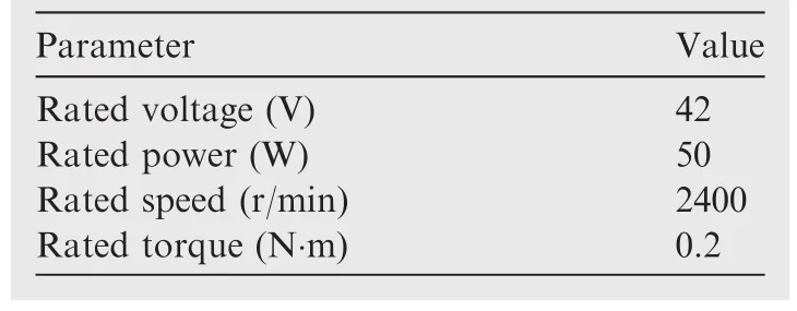
Table 1 Design specification of PMSM.
2.1.Structure design
As the key component of the EMA system,the PMSM has a significant influence on the safety of the ETU.To meet the reliability requirement of aircraft critical equipment,we design a six-phase PMSM structure with concentrated single-layer windings,due to its great fault isolation ability.As a result,the slot number is selected as 12.For the pole number design,on one hand,the phase winding can obtain a bigger fundamental factor when the slot number and the pole number are close.On the other hand,the total harmonic distortion and electrical frequency increase as the pole number increases.Therefore,the pole number of the six-phase PMSM is selected as 10.Fig.2 shows the structure of the stator and rotor.
In addition,when a short-circuit fault occurs,the winding will form a closed circuit,in which a short-circuit current will be produced by a back electromotive force.With the problems of producing a braking torque and increasing the copper loss,the short-circuit current should be restrained.LetIsdenote the short-circuit current,Ethe back electromotive force,ωethe electrical angular frequency,Lsthe phase inductance,andRsthe phase resistance.The short-circuit current can be represented as
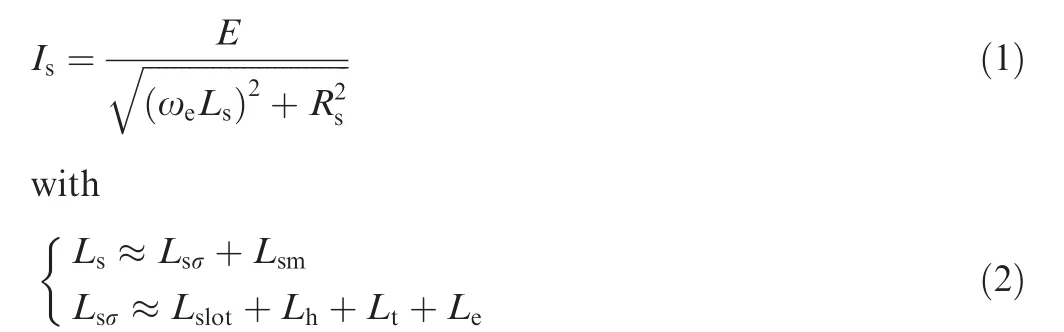
whereLsσis the leakage inductance,Lsmis the excitation inductance,Lslotis the slot leakage inductance,Lhis the harmonic leakage inductance,Ltis the tip leakage inductance,andLeis the end leakage inductance.Eq.(1)shows that the short-circuit current depends on the back electromotive force and impedance.To restrain the short-circuit current,a high slot leakage inductance is usually achieved via the design of the stator slot shape.Assuming that the simplified model of a slot is shown as Fig.3,the slot leakage inductance can be represented as21
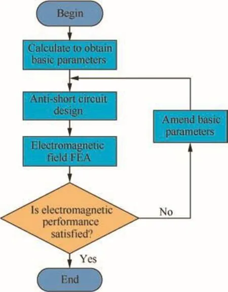
Fig.1 Flow chart of PMSM design.
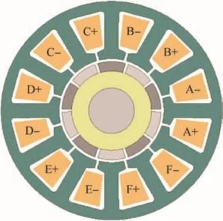
Fig.2 Structure of stator and rotor.
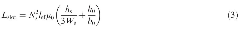
whereNsis the number of conductors of each phase,lefis the effective axial length,μ0is the permeability of vacuum,hsis the slot height,Wsis the slot width,h0is the slot opening height,andb0is the slot opening width.
Eq.(3)shows that the parametersNs,lef,hs,Ws,h0,andb0can all be modified to increase the slot leakage inductance.However,modifyingNsandlefwill cause changes of other performance indexes of the PMSM.In addition,the effect of modifyinghsandWsto increase the slot leakage inductance is limited when the outer diameters of the stator and rotor are fixed.Therefore,an effective method of increasing the slot leakage inductance is to modify the ratio ofh0tob0.According to Eqs.(2)and(3),it can be seen that the slot leakage inductance will increase linearly as the ratio ofh0tob0increases.In addition,the required short-circuit current can be obtained based on the ampere density,which is set as 8 A/mm.2Then,according to the short-circuit current and the phase back electromotive force,the phase self-inductance is determined.Finally,the demanded phase self-inductance is achieved via modifyingh0andb0.Based on the design processes above,we complete the PMSM design.The main parameters of the PMSM are shown in Table 2.
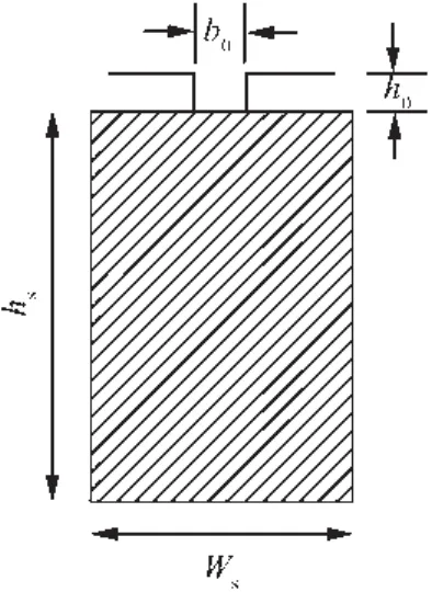
Fig.3 Simplified model of a slot.
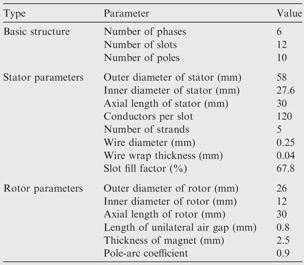
Table 2 Main parameters of PMSM.
2.2.Electromagnetic field FEA
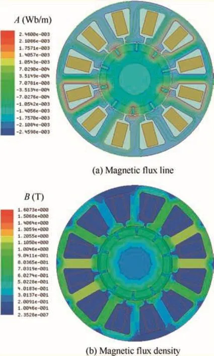
Fig.4 Magnetic flux line and magnetic flux density of PMSM with no load.
After the structure design,the electromagnetic field FEA of the PMSM is conducted to verify the electromagnetic performance.Fig.4(a)shows the magnetic flux line of the PMSM with no load,in which A denotes the magnetic vector potential.There are few magnetic flux lines coupling between each phase,indicating the great magnetic isolation capability of the PMSM.Fig.4(b)shows the magnetic flux density of the PMSM with no load,in which B denotes the magnetic flux density.The maximum value of the magnetic flux density is about 1.3 T,located in the stator tooth,which does not reach the saturation value of a silicon steel sheet.Fig.5 shows the self-inductance and mutual inductance of the PMSM,respectively.The value of the self-inductance is about 5.5 mH,while the value of the mutual inductance is only about-86 μH,which can also indicate the magnetic isolation between each phase.Fig.6 shows the short-circuit phase current at rated speed,whose root mean square value is 1.945 A.With the cross-sectional area of each coil being 0.245 mm2,the ampere density can be obtained as 7.939 A/mm2,which meets the design specification requirement(no more than 8 A/mm2).Therefore,the designed PMSM can effectively restrain the short-circuit current.
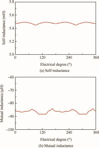
Fig.5 Self-inductance and mutual inductance of PMSM.
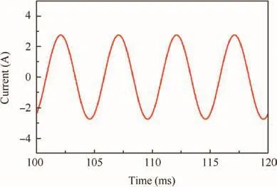
Fig.6 Short-circuit phase current at rated speed.
3.System modeling
To compare the position servo performances of a redundant PMSM and a fault-tolerant PMSM,a dual-redundancy PMSM(DRPMSM)system and a six-phase fault tolerant PMSM(FTPMSM)system are built based on the same PMSM designed in the previous section,which can avoid the influence from the difference in stators and rotors.
3.1.Mathematical model of PMSM
To simplify the analysis,assumptions can be made as follows:
(1)The air-gap magnetic fields generated by stators and rotors are both sinusoidal.
(2)Magnetic saturation of the iron core,hysteresis,and eddy are all ignored.
(3)All phases are symmetrical.
(4)The mutual inductance is ignored.
Then,the voltage equation and flux linkage equation can be given by
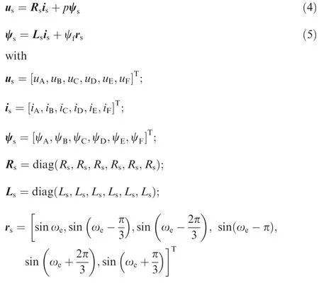
where us,is,and ψsare the vectors of phase voltage,current,and flux linkage,respectively;Rsand Lsare the matrices of resistance and inductance,respectively;ψfis the amplitude of the permanent magnet flux;rsis the matrix of flux linkage coefficients;pis the differential operator d/dt.
3.2.Control model of DRPMSM
The DRPMSM system is built by adopting two sets of three phase windings as redundancy.Each set of three phase windings is powered by a three-phase full-bridge inverter,as shown in Fig.7.
Considered as two PMSMs with the same rotor,the DRPMSM system can be controlled by the duald-qtransformation vector control method.Fig.8 shows the duald-qtransformation vector control structure of the DRPMSM system,in which APR,ASR,and ACR represent the automatic position regulator,automatic speed regulator,and automatic current regulator,respectively.Via coordinate transformation,the
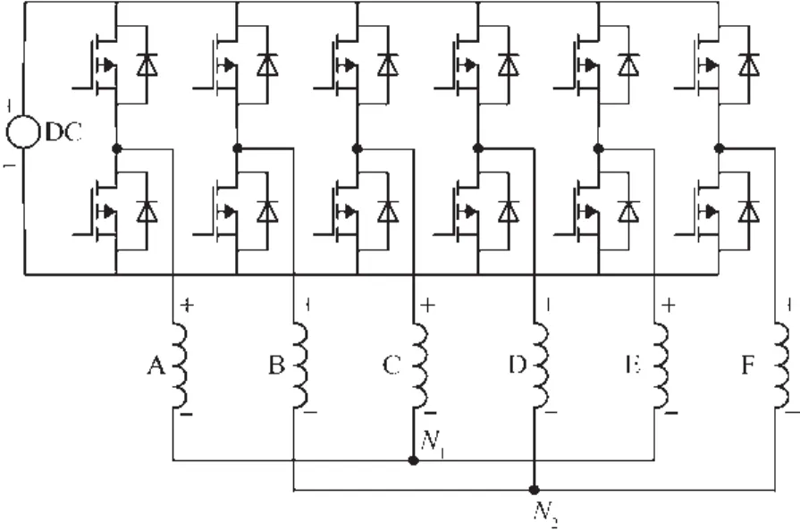
Fig.7 Inverter structure for the DRPMSM.
voltage equation and flux linkage equation can be transformed intod-qcoordinates,and then we can have
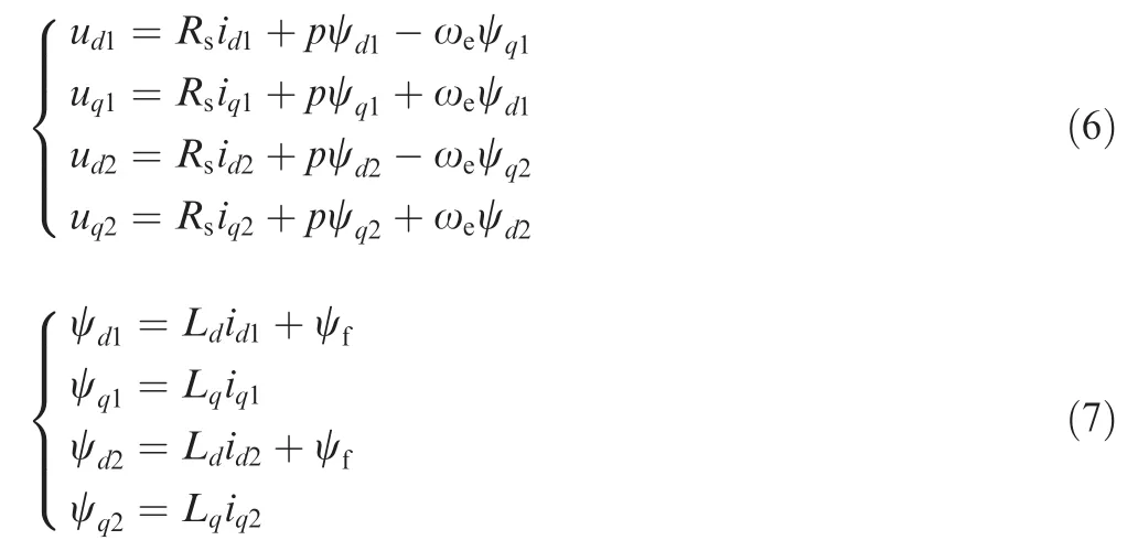
whereud1anduq1are the direct axis and quadrature axis voltages of the first redundancy of the DRPMSM,respectively;ψd1and ψq1are the direct axis and quadrature axis flux linkages of the first redundancy of the DRPMSM,respectively;id1andiq1are the direct axis and quadrature axis currents of the first redundancy of the DRPMSM,respectively;ud2anduq2are the direct axis and quadrature axis voltages of the second redundancy of the DRPMSM,respectively;ψd2and ψq2are the direct axis and quadrature axis flux linkages of the second redundancy of the DRPMSM,respectively;id2andiq2are the direct axis and quadrature axis currents of the second redundancy of the DRPMSM,respectively;LdandLqare the synchronous inductances of direct axis and quadrature axis,respectively.For a non-salient pole motor,we can have

Then,the electromagnetic power and electromagnetic torque can be given by
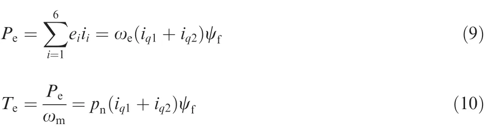
whereeiis the instantaneous phase back electromagnetic force;iiis the instantaneous phase current;ωmis the mechanical angular frequency;pnis the number of pole pairs.Eqs.(6)–(10)show that the DRPMSM is equivalent to two three phase PMSMs,whose electromagnetic torque is the sum of those of the two PMSMs.
3.3.Control model of the six-phase FTPMSM
Based on the same PMSM,the FTPMSM system can be built when connecting each phase winding with an H-bridge inverter.Fig.9 shows the inverter structure for the FTPMSM.
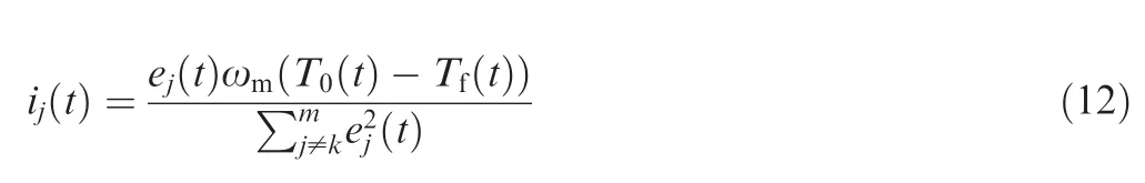
The FTPMSM system adopts the optimal torque control method,as shown in Fig.10.This control method considers the minimum copper loss as the objective function and zero torque ripple as the constraint condition.22,23Then,Lagrange cost function can be constructed as
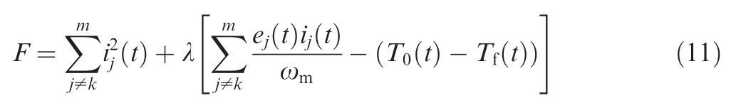
whereej(t)andij(t)are the transient phase induced voltage and current,respectively;T0(t)andTf(t)are the transient electromagnetic torques of normal phases and fault phases,respectively;kis the set offault phases.The normal phase current command can be given by
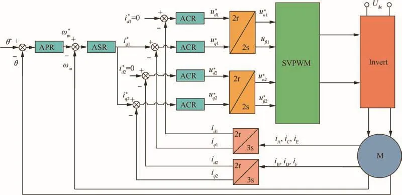
Fig.8 Dual d-q transformation vector control structure.
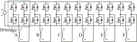
Fig.9 Inverter structure for FTPMSM.
This control method can directly control the current of each phase in the static coordinate,without complex coordinate transformation.
4.Position servo performance analysis
4.1.Theoretical analysis
As a position servo system,an EMA demands the PMSM system to have great servo performance,which depends on the rapidity and stability of position response.Assume that the position instruction is
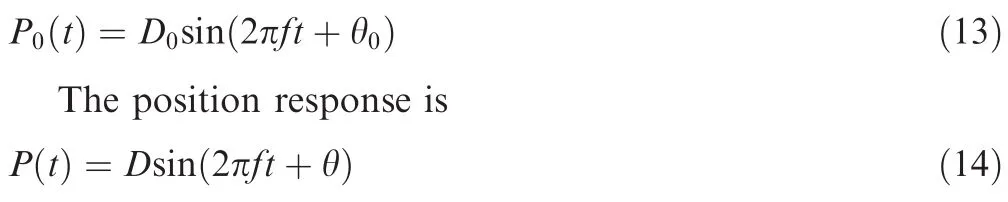
Then,the position servo performance can be evaluated according to the amplitude attenuation and phase shift of the position response as
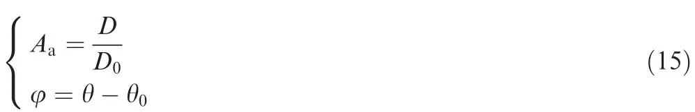
whereAais the amplitude attenuation,and φ is the phase lag.The position servo performance is better asAais closer to 1 and φ to 0.According to Eq.(14),the angular velocity and the angular acceleration can be given by
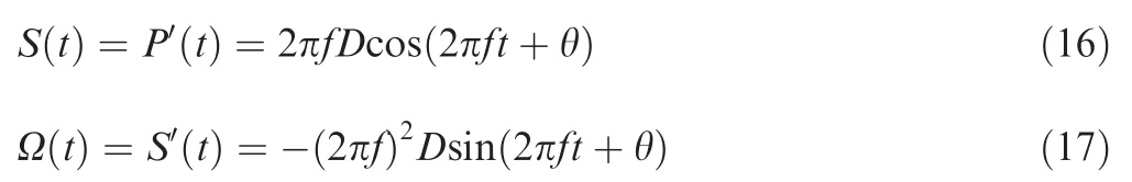
By the laws of classical mechanics,it can be seen that the position response of the PMSM depends on its angular velocity and further depends on its angular acceleration.As shown in Eq.(17),the amplitude of angular acceleration is in direct proportion to the amplitude and the square of the frequency of the position.In addition,the motion equation can be given by
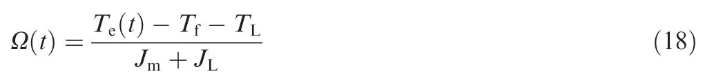
whereTe(t),Tf,andTLare the electromagnetic torque,friction torque,and load torque,respectively;JmandJLare the rotational inertia of the PMSM and the load,respectively.Under the same load condition,the angular acceleration reflects the electromagnetic torque of the PMSM.The rapidity and stability of the electromagnetic torque determine the position servo performance of the PMSM.For the DRPMSM system,as shown in Eq.(10),the electromagnetic torque is in proportion to the sum of quadrature axis current of the two three-phase windings.When a fault occurs,only the electromagnetic torque of normal phases is under control.On the other hand,for the FTPMSM system,the total electromagnetic torque of all phases is under control.However,the relationship between the phase current and the electromagnetic torque is more complex because of asymmetric operation under the fault condition.Even so,the phase currents are also in the trend of increasing with an increase of the electromagnetic torque.
In addition,saturation nonlinear elements also exist in the actual system,such as the limits of the electromotive force and winding current.They will limit the angular velocity and electromagnetic torque,which will affect the position servo performance of the PMSM.
4.2.Simulation analysis
Based on the designed PMSM,the simulation models of the DRPMSM system and the FTPMSM system are established in Ansoft simulation environment,and the position servo performance is analyzed and compared between these two PMSM systems under normal and fault conditions.In the simulation,the rotational inertia of the PMSM and the load inertia are 1.3×10⁻⁵kg m2and 2.18×10⁻⁴kg m2,respectively,and the load torque is 0.1 N·m.
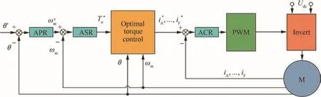
Fig.10 Optimal torque control structure.
The DRPMSM system operates in hot backup mode.That is,two sets of the three-phase windings are running at the same time under the normal condition.When an open-circuit fault occurs,the three-phase winding corresponding will be disconnected.In addition,it will be three-phase shorted if a shortcircuit fault occurs.Given a sinusoidal position command with the 30°peak value at 10 Hz,the position response of the DRPMSM under the normal condition is shown in Fig.11(a).Meanwhile,Fig.11(b)and(c)show the electromagnetic torque and phase currents,respectively.Under the fault condition,the position response of the DRPMSM is the same as that under the normal condition,with doubled current as shown in Figs.12 and 13(a).The electromagnetic torque produced by short-circuit fault phases is not under controlled,but it can still be compensated by normal phases because of the outer loop control.Fig.13(b)shows the total electromagnetic torque of all phases,which is the same as in Fig.11(b).In addition,when the electromagnetic torque is at its maximum value,the short-circuit phases will not generate a braking torque because of the zeroth speed.That is,a short-circuit fault will not increase the maximum electromagnetic torque of normal phases.
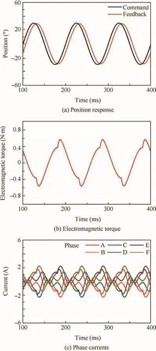
Fig.11 Position response,electromagnetic torque,and phase currents of DRPMSM under the normal condition.
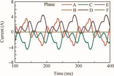
Fig.12 Phase currents of DRPMSM with an open-circuit fault.
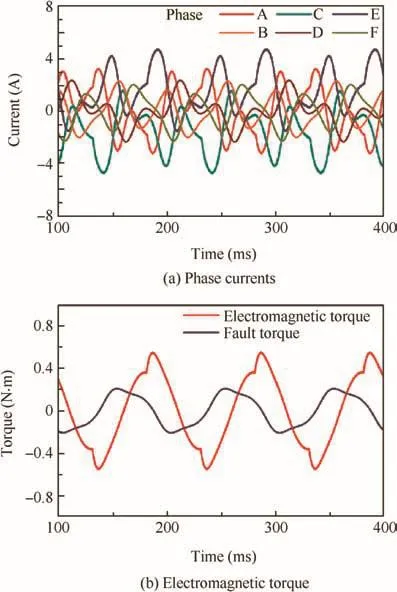
Fig.13 Phase currents and electromagnetic torque of DRPMSM with a short-circuit fault.
For the six-phase FTPMSM system,given a sinusoidal position command with the 30°peak value at 10 Hz,the position response under the normal condition is shown in Fig.14(a).Meanwhile,Fig.14(b)and(c)show the electromagnetic torque and phase currents,respectively.Under the fault condition,the position response of the FTPMSM is also the same as that under the normal condition,and the phase currents will increase as the number offault phases increases,as shown in Table 3.Fig.15 shows the phase currents of the FTPMSM with the third open-circuit fault and the second short-circuit fault,respectively.
The simulation results show that the position servo performances of the DRPMSM and the FTPMSM are similar under small amplitude position commands.It can be concluded that the two PMSMs have similar control performances for the electromagnetic torque,even though they have different system structures and control strategies.Especially for the DRPMSM,under the short-circuit fault condition,the position servo performance is not affected by the braking torque from fault phases.
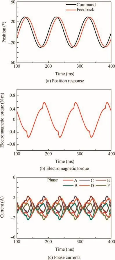
Fig.14 Position response,electromagnetic torque,and phase currents of FTPMSM under the normal condition.
However,because of the different inverter structures,the DRPMSM system and the FTPMSM system have different speed ranges under the same busbar voltage,which will limit their position servo performances.For the DRPMSM and the FTPMSM,the busbar voltage limits the line voltage and phase voltage,respectively.Thus,the phase voltage value of the FTPMSM is about ---3■ times that of the DRPMSM,and so is the speed range.Consequently,the FTPMSM will have a better position servo performance with a large amplitude position command.Given a sinusoidal position command with the 360-degree peak value at 10 Hz,the position and speed response of the DRPMSM are shown in Fig.16(a)with no load,while Fig.16(b)shows those of the FTPMSM.Compared with the FTPMSM,because of a smaller speed range,the position response of the DRPMSM is degenerative obviously when the speed saturates.
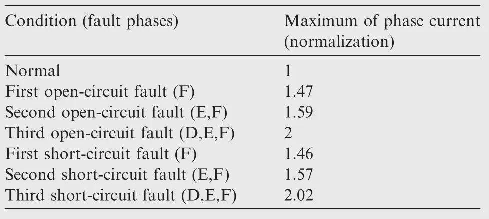
Table 3 Maximum of the phase current under different conditions.
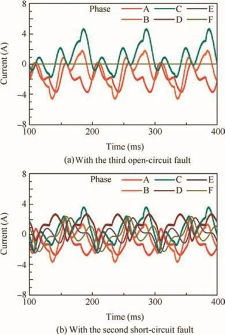
Fig.15 Phase currents of FTPMSM with the third open-circuit fault and the second short-circuit fault.
5.Variable structure PID control
In an actual PMSM control system,there are several saturation elements such as the input limits of speed loop, current loop, and pulse-width modulation (PWM) module. They may degrade the position servo performance of the PMSM,especially the input limit of the current loop,which will affect the electromagnetic torque directly.To solve this problem,a variable structure PID control strategy is proposed in this section.
The PMSM system for the EMA is a typical position servo system,whose control structure can be simplified if only position loop and current loop are adopted.24,25However,in order to limit the maximum speed,a three-closed-loop control structure with a speed loop is adopted in this paper,and only proportional regulation is used in the speed loop regulator to improve the rapidity of the control system.Figs.17 and 18 show the control models of the DRPMSM system and the FTPMSM system with limiting regulators,respectively,in whichGp(s),Gs(s),Gi(s),andGPWM(s)denote the position regulator,speed regulator,current regulator,and PWM converter;Lims,Limi,and Limu denotetheinputlimit regulators of the speed loop,current loop,and PWM module.
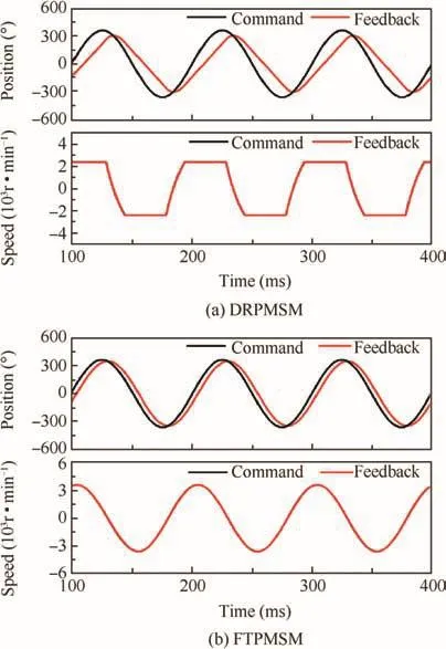
Fig.16 Position and speed responses of DRPMSM and FTPMSM.
Since the speed loop is a proportion element,the given value of current can be adjusted by regulating the output of the position regulator.Therefore,to ensure the phase current is always less than the saturation value,a variable structure PID control strategy for the position regulator is proposed.Meanwhile,in order to ensure the rapidity of the position response,dominant proportional regulation and integral output limit are adopted in the position regulator.The position regulator can be given by
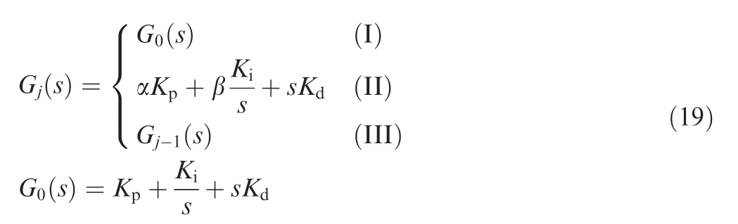
whereG0(s)is the original position regulator;Gj(s)is thejcycle position regulator;Kp,Ki,andKdare the proportional coefficient,integral coefficient,and differential coefficient,respectively;α and β are the adjustment coefficients of proportion and integration,which are in the range of 0–1.Condition(I)denotes that the maximum phase current is less than the threshold valueILwithin timet;condition(II)denotes that the transient maximum phase current is greater than the threshold valueIH;condition(III)denotes the other conditions except conditions(I)and(II).
To verify the validity of the variable structure PID control strategy,simulation analyses are conducted.As shown in Fig.19(a),the DRPMSM system switches to single redundancy after an open-circuit fault at the time of 0.5 s.Meanwhile,with the phase currents increasing to the saturated value,the position servo performance degrades seriously,whose phase lag exceeds 90°.Fig.19(b)shows the position response of the DRPMSM adopting the variable structure PID control strategy.It can still keep great servo performance,with a 45°phase lag,when phase currents become saturated.In addition,compared with the traditional PID control strategy,the position response with the variable structure PID is better in stationarity.Same in the FTPMSM system,Fig.20 shows the position responses of the FTPMSM with current saturation adopting the traditional and variable structure PID control strategies,respectively.Simulation results indicate that the variable structure PID control strategy can improve the position servo performance effectively after the current saturation.
6.Experimental validation
6.1.Experimental platform
To verify the simulation results,an experimental platform based on the designed PMSM is established,including a PMSM,a drive controller,a dynamometer,a power supply,and a CAN bus demonstration platform,as shown in Fig.21.The rotational inertia of the dynamometer is about 2.18×10⁻⁴kg m2.Based on the experimental platform,the position servo performances of the DRPMSM and the FTPMSM are tested and compared.The variable structure PID control strategy is also verified.
6.2.Servo performance experiment
Via different configurations of the windings and inverter,the PMSM system is configured to the DRPMSM system and the FTPMSM system,respectively.The load torque is 0.1 N·m,and the frequency of position command is 10 Hz.Fig.22(a),(b),and(c)show the position responses and phase currents of the DRPMSM system under the normal condition,with the open-circuit fault,and the short-circuit fault,respectively.Meanwhile,Fig.23(a),(b),and(c)show the position responses and phase currents of the FTPMSM system under the normal condition,with the third open-circuit fault,and the second short-circuit fault,respectively.Same as the simulation results,the DRPMSM system and the FTPMSM system have similar position servo performances with a small amplitude position command.In addition,the servo performance is almost not affected under the fault condition,and only phase currents increase.
Meanwhile,due to the different speed ranges,the position servo performance of the FTPMSM system is better than that of the DRPMSM system with a large amplitude position command.Given a sinusoidal position command with the 360-degree peak value at 10 Hz,Fig.24 shows the position and speed responses of the DRPMSM system and the FTPMSM system with no load,respectively.Compared with the FTPMSM system,the position response of the DRPMSM is degenerative obviously because of the speed saturation.
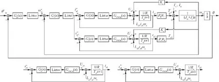
Fig.17 Control model of DRPMSM based on d-q transformation.
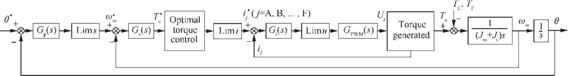
Fig.18 Control model of FTPMSM based on optimal torque control.
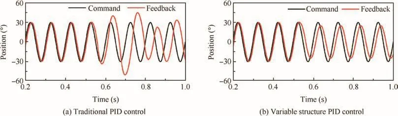
Fig.19 Position responses of DRPMSM with current saturation.
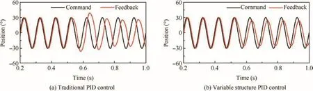
Fig.20 Position responses of FTPMSM with current saturation.
6.3.Variable structure PID control experiment
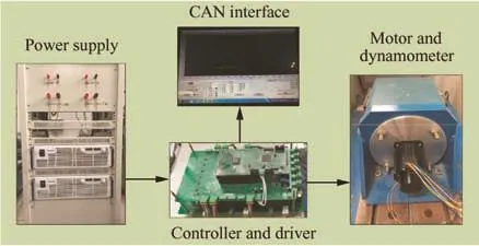
Fig.21 Experimental platform.
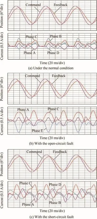
Fig.22 Position responses and phase currents of DRPMSM.
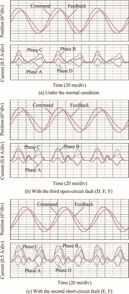
Fig.23 Position responses and phase currents of FTPMSM.
Restricted by the winding current density,the phase current limit of the PMSM is set as 4 A.To verify the variable structure PID control strategy,an experiment is conducted similarly to the simulation.Fig.25 shows the position responses of the DRPMSM system with current saturation by the traditional PID and variable structure PID control strategies.The DRPMSM operates under the normal condition before the fault point and switches to single redundancy when the open-circuit fault occurs.Current q1denotes the quadratureaxis current of the normal three-phase winding.These figures show the phase lag of the DRPMSM system with the traditional PID and variable structure PID are about 50 degrees and 42 degrees,respectively,when currents are saturated.Fig.26 shows the position responses of the FTPMSM system with current saturation by the traditional PID and variable structure PID control strategies.When the fault occurs,the FTPMSM switches to the third open-circuit fault from the second open-circuit fault.These figures show that the phase lag of the FTPMSM system with the traditional PID and variable structure PID are about 48 degrees and 37 degrees,respectively,when currents are saturated.Therefore,under the condition of current saturation,the variable structure PID control strategy can reduce the phase lag of the position response.The results also show that it can improve the stationarity of the position response,that is,the variable structure PID control strategy can improve the position servo performance effectively.
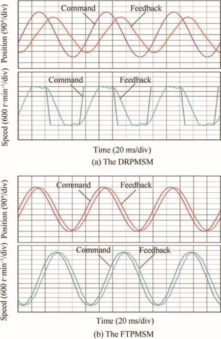
Fig.24 Position and speed responses of DRPMSM and FTPMSM.
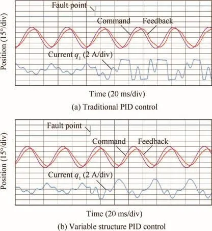
Fig.25 Position responses ofDRPMSM with current saturation.
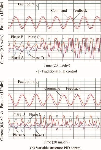
Fig.26 Position responses of FTPMSM with current saturation.
7.Conclusions
(1)A six-phase PMSM with high reliability for aeronautic EMAs is designed,which has good capabilities offault isolation and restraining short-circuit current.The PMSM can operate at dual-redundant mode and fault tolerant mode,respectively.
(2)The simulation and experimental results show that the DRPMSM system and the FTPMSM system have similar capabilities of electromagnetic torque control.However,the FTPMSM has better position servo performance with a large amplitude position command due to the wider speed range.
(3)The position servo performance of the PMSM will not be affected by the open-circuit or short-circuit fault,only the phase currents increasing in proportion.In addition,compared with the open-circuit fault,the short-circuit fault of the same phases will not increase the maximum but the root mean square value of the normal phase currents.
(4)A variable structure PID control strategy is proposed,which can improve the position servo performance of the PMSM when the phase currents are saturated.
Acknowledgements
This work was supported by Aeronautical Science Foundation of China(No.2016ZC51025)and the Open Research Fund of Key Laboratory of Space Utilization,Chinese Academy of Science(No.20161201).
1.Lyshevski SE.Electromechanical flight actuators for advanced flight vehicles.IEEE Trans Aero Electron Syst1999;35(2):511–8.
2.Gerada C,Bradley KJ.Integrated PM machine design for an aircraft EMA.IEEE Trans Ind Electron2008;55(9):3300–6.
3.Villani M,Tursini M,Fabri G,Castellini L.High reliability permanent magnet brushless motor drive for aircraft application.IEEE Trans Ind Electron2012;59(5):2073–81.
4.Hao L,Namuduri C.Electromechanical regenerative actuator with fault-tolerance capability for automotive chassis applications.IEEE Trans Ind Appl2013;49(1):84–91.
5.Dixon R,Pike A.Application of condition monitoring to an electromechanical actuator:A parameter estimation based approach.Comput Control Eng J2002;13(2):71–81.
6.Guo H,Xing W.Development of electromechanical actuators.Acta Aeronaut Astronaut Sin2007;28(3):620–7[Chinese].
7.Villani M,Tursini M,Fabri G,Castellini L.Electromechanical actuator for helicopter rotor damper application.IEEE Trans Ind Appl2014;50(2):1007–14.
8.Woodburn D,Wu T,Zhou L,Hu Y,Lin YR,Chow L,et al.High performance electromechanical actuator dynamic heat generation modeling.IEEE Trans Aero Electron Syst2014;50(1):530–41.
9.Haylock JA,Mecrow BC,Jack AG,Atkinson DJ.Operation of a fault tolerant PM drive for an aerospace fuel pump application.IEE Pro Electr Power Appl1998;145(5):441–8.
10.Lu XH,Liang JH.A nonlinear model offault tolerant permanent magnet motors in the direct drive electromechanical actuator.Proc Chin Soc Electr Eng2012;32(18):145–51[Chinese].
11.Guo H,Xu JQ,Kuang XL.A novel fault tolerant permanent magnet synchronous motor with improved optimal torque control for aerospace application.Chin J Aeronaut2015;28(2):535–44.
12.Guo H,Xu JQ.Fault tolerant control with torque limitation based on fault mode for ten-phase permanent magnet synchronous motor.Chin J Aeronaut2015;28(5):1464–75.
13.Hao ZY,Hu YW.Design and experimental analysis on the control system of high reliability fault tolerant permanent magnet motor used in electric actuator.Acta Aeronaut Astronaut Sin2013;34(1):141–52[Chinese].
14.Guo H,Xu JQ,Chen YH.Robust control offault-tolerant permanent-magnet synchronous motor for aerospace application with guaranteed fault switch process.IEEE Trans Ind Electron2015;62(12):7309–21.
15.Bianchi N,Bolognani S,Dai PM.Strategies for the fault-tolerant current control of a five-phase permanent-magnet motor.IEEE Trans Ind Appl2007;43(4):960–70.
16.Parsa L,Toliyat HA.Fault-tolerant interior-permanent-magnet machines for hybrid electric vehicle applications.IEEE Trans Veh Technol2007;56(4):1546–52.
17.Bojoi R,Levi E,Farina F,Tenconi A,Profumo F.Dual three phase induction motor drive with digital current control in the stationary reference frame.IEE Pro Electr Power Appl2006;153(1):129–39.
18.Bojoi R,Tenconi A,Griva G,Profumo F.Vector control of dualthree-phase induction-motor drives using two current sensors.IEEE Trans Ind Appl2006;42(5):1284–92.
19.Kallio S,Andriollo M,Tortella A,Karttunen J.Decoupled d-q model of double-star interior permanent magnet synchronous machines.IEEE Trans Ind Electron2013;60(6):2486–94.
20.Barcaro M,Bianchi N,Fornasiero E,Magnussen,F.Experimental comparison between two fault-tolerant fractional-slot multiphase PM mo-tor drives.International Symposium on Industrial Electronics;2010 July 4–7;Bari.Pisca-taway(NJ):IEEE Press;2010.p.2160–5.
21.El-Refaie AM,Zhu ZQ,Jahns TM,Howe D.Winding inductances offractional slot surface-mounted permanent magnet brushless machines.COMPEL:Int J Comput Math Electr Electron Eng2009;28(6):1590–606.
22.Atallah K,Wang JB,Howe D.Torque-ripple minimization in modular permanent-magnet brushless machines.IEEE Trans Ind Appl2003;39(6):1689–95.
23.Wang JB,Atallah K,Howe D.Optimal torque control of faulttolerant permanent magnet brushless machines.IEEE Trans Magn2003;39(5):2962–4.
24.Guo H,Yu YQ.DDV servocontrol system based on variablestructure PID control.Trans China Electrotech Soc2007;22(11):58–62[Chinese].
25.Wang W,Guo H,Xing W,Li YM,Wang DY.A control system for electrical/mechanical hybrid four-redundancy brushless DC torquemotor.ProcChinSocElectEng2010;30(6):100–4[Chinese].
24 August 2016;revised 7 December 2016;accepted 18 March 2017
Available online 14 June 2017
*Corresponding author.
E-mail address:xujinquan@buaa.edu.cn(J.XU).
Peer review under responsibility of Editorial Committee of CJA.
Production and hosting by Elsevier
http://dx.doi.org/10.1016/j.cja.2017.05.001
1000-9361©2017 Chinese Society of Aeronautics and Astronautics.Production and hosting by Elsevier Ltd.
This is an open access article under the CC BY-NC-ND license(http://creativecommons.org/licenses/by-nc-nd/4.0/).
Electro-mechanical actuators;
Fault tolerant;
Permanent magnet synchronous motor;
Redundancy;
Variable structure PID
control
杂志排行

CHINESE JOURNAL OF AERONAUTICS的其它文章
- Wake structure and similar behavior of wake profiles downstream of a plunging airfoil
- Self-sustained oscillation for compressible cylindrical cavity flows
- Numerical studies of static aeroelastic effects on grid fin aerodynamic performances
- A new vortex sheet model for simulating aircraft wake vortex evolution
- Linear stability analysis of interactions between mixing layer and boundary layer flows
- Aerodynamic multi-objective integrated optimization based on principal component analysis