Extrinsic calibration of a laser displacement sensor in a non-contact coordinate measuring machine
2017-11-20ChaoBIJianguoFANGKunLIZhijunGUO
Chao BI,Jianguo FANG,Kun LI,Zhijun GUO
Aviation Key Laboratory of Science and Technology on Precision Manufacturing Technology,Beijing Precision Engineering Institute for Aircraft Industry,Beijing 100076,China
Extrinsic calibration of a laser displacement sensor in a non-contact coordinate measuring machine
Chao BI*,Jianguo FANG,Kun LI,Zhijun GUO
Aviation Key Laboratory of Science and Technology on Precision Manufacturing Technology,Beijing Precision Engineering Institute for Aircraft Industry,Beijing 100076,China
In order to implement 3D scanning of those complicated parts such as blades in the aviation field,a non-contact optical measuring system is established in the paper,which integrates a laser displacement sensor,a probe head,the frame of a coordinate measuring machine(CMM),etc.As the output of the laser sensor directly obtained possesses the 1D length of the laser beam,it needs to determine the unit direction vector of the laser beam denoted as(l,m,n)by calibration so as to convert the 1D values into 3D coordinates of target points.Therefore,an extrinsic calibration method based on a standard sphere is proposed to accomplish this task in the paper.During the calibration procedure,the laser sensor moves along with the motion of the CMM and gathers the required data on the spherical surface.Then,both the output of the laser sensor and the grating readings of the CMM are substituted into the constraint equation of the spherical surface,in which an over-determined nonlinear equation group containing unknown parameters is established.For the purpose of solving the equation group,a method based on non-linear least squares optimization is put forward.Finally,the system after calibration is utilized to measure the diameter of a metallic sphere 10 times from different orientations to verify the calibration accuracy.In the experiment,the errors between the measured results and the true values are all smaller than 0.03 mm,which manifests the validity and practicality of the extrinsic calibration method presented in the paper.
©2017 Production and hosting by Elsevier Ltd.on behalf of Chinese Society of Aeronautics and Astronautics.This is an open access article under the CC BY-NC-ND license(http://creativecommons.org/licenses/by-nc-nd/4.0/).
1.Introduction
1.1.Motivation
Along with the gradual formation of global economic integration,the aviation and aerospace industry has already entered a brand-new developing stage,which may represent the comprehensive national strength of a country to a certain extent.In the new era of aviation and aerospace,both of opportunities and challenges exist.Therefore,how to keep enterprises,products,service,etc.in an invincible position has already become one of the focus topics that people pay the most attention.
Inthefieldofaeronauticalengineering,astheheartofanaircraft,the aero engine is the motive power pushing the airplane forward,whose properties may affect the safety and reliability offlights directly.1In an aero engine,there are so many blades,whosegeometriesmayhaveagreatinfluenceonitsdynamicperformance.Nowadays,with the fast development of the aviation industry,an aero engine of high performance is urgently needed,which puts forward high requirements of blades in both quality and quantity.2However,in order to produce so many blades meeting design requirements,accurate and effective measurement of blades in their manufacturing process needs to be executed.In general,for the purpose of making blades possess special dynamic performance, their surfaces are usually designed according to the principle of hydrodynamics.There fore,the surface of a blade belongs to a kind of spatial free surfaces appearing as the geometry of a strong twist,whose complexity and diversity will cause considerable difficulty in its measurement.3Consequently,new measuring methods and equipment are demanded urgently if all the blades are to be inspected.
Traditionally,the existing tactile coordinate measuring machines(CMMs)are widely utilized in the measurement of blades due to their mature technology and good applicability.A typical CMM,composed of three linear axes and one contact probe,has found its great potential in such applications as precision measurement,quality control,reverse engineering,etc.However,although high accuracy and reliability can be achieved,employing a touch probe may lead to disadvantages such as long operating time,low acquiring efficiency,deformation at the contact point by the measuring force,etc.4Thus,the level of automation and intellectualization is low,and the measuring efficiency cannot meet the detection demand of volume blades,which requires acquisition of lots of points on their complex surfaces.
Considering the above,many researchers have focused their attentions on new non-contact measuring methods and equipment,which are made possible by advances in sensing devices.Currently,almost all the non-contact detecting systems for 3D profilometry are based on optical technologies because they are much easier to find their applications in engineering.With advantages of small volume,high response frequency,fast measuring speed,remote and non-destructive evaluation,etc.,laser sensors have become a new trend in dimension metrology.5In so many kinds of laser sensors,those based on the principle of optical trigonometry have already entered the market from laboratory,i.e.,laser displacement sensors.At moderate ranges,laser displacement sensors perform accurate and fast measurement and are easy to implement,so they are quite popular for 3D measurements.6Therefore,if a piece of equipment can combine a laser sensor with a traditional CMM,the advantages of them both will be taken altogether and their disadvantages will be compensated by each other to some extent,which will lead to much faster measurement than using the tactile method alone.7
1.2.Related work
In order to complete 3D scanning tasks,a laser sensor is always installed on the terminal ofZaxis of a CMM through a probe head.The function of the former is to drive the sensor to implement a motion trajectory,while that of the latter is to change the spatial orientation of the sensor according to the normal direction of a target surface.In the measuring procedure,along with the linear movement of the CMM and the rotation of the probe head,the laser sensor can collect the complete point cloud of the target surface.However,there are several difficulties in the integration of the laser sensor and the CMM,one of which is the extrinsic calibration of the laser sensor used for data matching.As the output of the laser sensor is a 1D length while the measured data(i.e.,the 3D coordinates of measured points)must be given in terms of 3D expression in the world coordinate system,a calibration model used for determining the orientation of the sensor should be established.
Many researchers are devoting their efforts in the integration of the optical scanning technology and the traditional coordinate measuring technology,which leads to some new measuring means and devices.Nishikawa et al.developed a non-contact on-machine measuring system by installing a laser displacement sensor on a multi-functional machine tool,which can be used to measure the glossy metal surface of a turbine blade.Through calibration of the zero position vector of the sensor and the direction vector of the laser beam,the 3D coordinates of a measurement point can be calculated,which becomes the key link of the system.8
Lee and Shiou developed a novel optical non-contact probe that can inspect the position and orientation of a free form surface,which comprised a five-laser-beam projector and a CCD.In actual utilization,the probe can be easily integrated on a commercial three-axis platform.Besides,a scheme for calibrating and making measurements using the probe was proposed and verified experimentally.9However,in the system,the direction of the laser is fixed to be parallel to theZaxis of the platform,which severely limits the freedom of the system as well as the application scope.Considering the incapability of changing the direction of the non-contact probe continuously according to the fluctuation of a surface to be detected,the system is not competent for measuring parts with complicated structures.
Sun and Li independently developed a four-coordinate measuring system to detect a blade surface in a rapid and accurate way,which was composed of a laser displacement sensor and a four-coordinate measuring body including three vertical coordinates and a rotary table.In the measuring procedure,the measured blade is fixed on the rotary table by a special fixture,which can make the axis of the blade consistent with theZaxis.By moving the laser sensor along theZaxis,characteristic sectionals of the blade at different heights can be measured.10However,the sensor was limited to one fixed orientation(the laser beam had to be perpendicular to theZaxis),which practically precluded inspection of complicated targets requiring multi-axis motions and multiple orientations of the laser displacement sensor.
Xie et al.proposed a five-axis laser scanning system integrated with a CMM,a laser displacement sensor,and a pH10 rotary head.In their work,an ‘equivalent probe”approach was presented for the system verification and an iterative verifying process was adopted to eliminate the verification error caused by the inclination error of the laser sensor.11–13However,in the procedure,the laser beam sensor is equivalent to a trigger probe and it needs to keep the length of the laser beam unchanged,which is so difficult to control.
Che and Ni set up a multiple-axis laser-stripe sensor integrated into a CNC system for 3D measurement.In order to implement measurement of complex featured parts requiring multiple-axis motions and multiple orientations of the laser sensor,they presented a ball-target-based method for the extrinsic calibration of the 3D scanning system,which can be used to determine the relationship between the sensor and the manipulator.14
Jorge et al.presented a technique for intrinsic and extrinsic calibrations of a laser triangulation sensor integrated in an articulated arm coordinate measuring machine,in which a one-step calibration method to obtain both intrinsic and extrinsic parameters of the laser sensor by means of a single gauge object was developed15.The presented method was also valid for sensors integrated in robot arms and CMMs.16Nevertheless,although the contactless measurement sensor based on structured light can provide suitably accurate values for most reverse engineering applications,it is not sufficient for metrological inspection tasks.
Liu and Chen installed a laser triangulation sensor on a CMM through a probe head to implement non-contact scanning and measuring.In the procedure of calibration of the sensor,they adopted an improved genetic algorithm and established an error model of the installation posture of the laser sensor.In addition,they determined the transformation relationship from the output of the sensor to the coordinate system of the CMM.17
1.3.Overview of this approach
In our previous research,as to the issue of extrinsic calibration of a laser displacement sensor in a non-contact optical coordinate measuring system,a method based on parameter substitution was described,which could be used to determine the unit direction vector of the laser beam.18Although a mathematic model has been established,there are several shortcomings in practical applications.Specifically speaking,the movement of the CMM and the acquisition of the sensor are not simultaneous in the calibration procedure.The CMM moves the sensor to one position and then stops,and the sensor collects measuring data at this moment.Afterwards,the CMM moves it to the next position,and the same process is executed until the end of calibration,which may be very time-consuming and clumsy as a result of the starting and stopping in the calibration.Therefore,an extrinsic calibration method of a good efficiency and a high automation level needs to be studied.
For the purpose of measuring the surfaces of blades in an accurate and efficient way,a non-contact coordinate measuring system based on the optical inspection technology is built up in the paper,which can be utilized to create the 3D point cloud of complex surfaces.In the system,the traditional contact probe is replaced by a non-contact laser triangulation sensor,which is attached to the end ofZaxis of a CMM through a probe head to realize five degrees of freedom motion.In order to derive the 3D coordinates of a target point from the 1D output of the sensor,the spatial orientation of the laser beam should be determined by calibration.Recently,no extrinsic calibration technique is available for this kind of integrated system.Therefore,a new extrinsic calibration method is proposed in the paper.In the calibration procedure,a metallic sphere used for calibration is fixed on the platform.The CMM moves the laser sensor along several certain space lines in small increments,and the sensor acquires required data at each increment position.With the output of the gratings and the sensor,an overdetermined non-linear equation group is set up through the constraint condition of the spherical surface,which contains the unit direction vector of the laser beam.As to the unknown parameters needed to be solved,a solving method based on the non-linear least squares optimization is adopted.Therefore,the 1D output of the laser sensor can be transformed into the 3D coordinates of the target point,which lays a solid foundation for the following creation of a point cloud.
After a brief review and introduction,the remainder of the paper is organized as follows.The measuring principle of the laser displacement sensor is introduced in Section 2.Then,coordinate systems used in the measuring procedure are described in Section 3.Afterwards,the calibration model and algorithm development are discussed in Section 4.Section 5 provides the configuration of the whole system.Next,experiments and results are shown in Section 6.Finally,conclusions of this piece of work and discussion of possible future direction are presented in Section 7.
2.Measuring principle of optical trigonometry
Nowadays,as a kind of optical sensors,laser displacement sensors are the most commonly used ones in the field of dimensional metrology as a result of their versatility and the fact that they are one of the most accurate detectors based on structured light.As can be seen in Fig.1,a laser displacement sensor is principally composed of a laser diode,a converging lens,an optical filter,a receiving lens,a position sensitive detector(PSD),etc.,all of which are the simplest configuration of a triangulation measuring system.19
The sensor is based on the principle of optical trigonometry,which can be described as follows.First of all,the axis of the laser diode,the optical axis of the receiving lens,and the linear array of the PSD are all in the same plane,and the optical axis of the receiving lens is perpendicular to the PSD.Then,a laser beam emitted from the laser diode focuses on the target surface through the converging lens,which can form a light spot of a tiny diameter on the surface.Afterwards,the diffuse reflection of the spot is collected by the receiving lens at another angle so that an imaging point is formed on the PSD.In the measuring procedure,if the position of the light spot changes due to the displacement of the target surface,the position of the imaging point on the PSD will change as well.20Suppose that the displacement of the surface isx,and that of the imaging point on the PSD caused by it isx'.Based on the theory of optical triangulation reflection,xcould be calculated byx'as
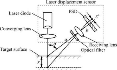
Fig.1 Structure diagram of a laser displacement sensor.
where θ is the angle between the axis of the incident laser beam and the optical axis of the receiving lens,athe distance between the target surface and the receiving lens,whilebthe distance between the receiving lens and the PSD.
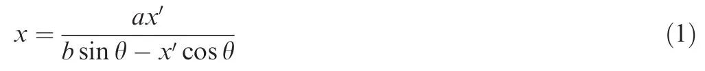
In practical applications,a laser displacement sensor is always applied cooperatively with a CMM so as to realize 3D scanning and measuring.21As the part to be measured usually has a complicated structure,it requires the convenience of changing the orientation of the laser sensor diversely and automatically according to the shape of the part.Thus,a probe head with two axes of rotation is mounted onto theZaxis of the CMM,and the laser sensor is jointed onto the probe head,which leads to a measuring system offive degrees offreedom combined with the three linear axes of the CMM.Enabling the sensor to rotate to any angle needed,the integrated system of multiple degrees of freedom allows the best view of a target.As can be seen in Fig.2,a laser displacement sensor is installed on the mobile terminal ofZaxis of a CMM through a probe head in the paper,which can be used to change the orientation of the laser sensor so as to accomplish a scan of the whole target surface.In the inspecting process,the sensor projects a laser beam onto the surface and forms a light spot noted asT,in which the output of the sensor is the 1D length of the laser beam denoted asL.For deriving the 3D coordinates ofT,the coordinate systemOS-XSYSZSis established at the zero point of the laser beamOS,in which the directions ofXS,YS,andZSaxes are all parallel to the corresponding axes of the CMM.In order to acquire the spatial coordinates ofTinOSXSYSZS,the unit direction vector of the laser beam expressed by(l,m,n)should be determined by calibration.
As shown in Fig.2,the 3D coordinates ofTinOS-XSYSZScan be expressed as(xT,yT,zT),which can be shown as
3.Coordinate systems
Fig.2 Coordinate system of the laser displacement sensor.
For the purpose of deriving a complete point cloud,it needs to scan the target surface from different visual angles and azimuth by the sensor and then piece together all the measuring data collected.Therefore,the coordinates of points from multiple perspectives should be transformed into a unified world coordinate system.Consequently,three rectangular coordinate systems established in the non-contact coordinate measuring system may be employed in the construction of the whole point cloud.They are the world coordinate system denoted asOW-XWYWZW,the base coordinate systemOBXBYBZB,and the sensor coordinate systemOS-XSYSZS,respectively,all of which meet the requirement of the right hand rule,as can be seen in Fig.3.
(1)The world coordinate systemOW-XWYWZW,which is fixed on the CMM.InOW-XWYWZW,the originOWis the home position of theX,Y,andZaxes of the CMM,which is determined when the CMM is homing.Moreover,the directions and scales ofXW,YW,andZWare all the same as those ofX,Y,andZ.
(2)The base coordinate systemOB-XBYBZB,the origin of which is just the center of the standard sphere fixed on the platform of the CMM.Meanwhile,the directions and scales ofXB,YB,andZBare all the same as the corresponding axes of the CMM.
(3)The sensor coordinate systemOS-XSYSZS,which is fixed on the laser beam.Its origin is the zero output of the laser sensor.In addition,the directions and scales ofXS,YS,andZSare all the same as those ofX,Y,andZrespectively.
In order to derive the 3D coordinates of a light spot and then transform them into the world coordinate system to complete the construction of the whole point cloud,it needs to transform the measuring values of the laser sensor intoOW-XWYWZW.As shown in Fig.3,the transformation sequence isOS-XSYSZS→OB-XBYBZB→OW-XWYWZW.The detailed procedure is described as follows.
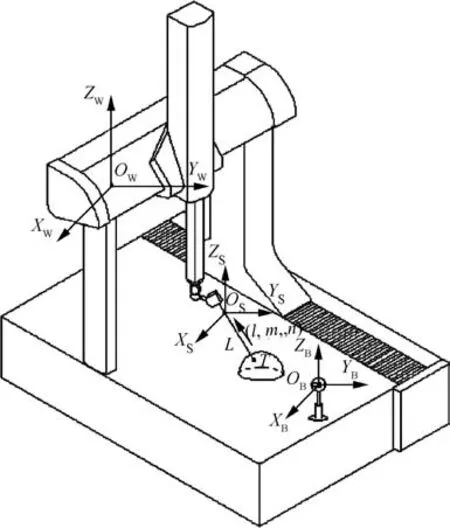
Fig.3 Three rectangular coordinate systems.
Firstly,the coordinates of the light spot(xT,yT,zT)can be transformed into the base coordinate systemOB-XBYBZB,in which R1and T1are the rotation and translation matrices fromOS-XSYSZStoOB-XBYBZB,respectively.As their corresponding axes are parallel,matrices R1and T1can be expressed as
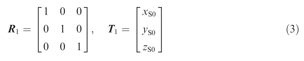
In the above,(xS0,yS0,zS0)represents the coordinates of the originOSinOB-XBYBZB,which could be derived through the extrinsic calibration procedure of the sensor.In this way,the coordinates of the light spotTdenoted as(xB,yB,zB)inOB-XBYBZBcan be expressed as

In the same way,R2and T2are used to denote the rotation and translation matrices fromOB-XBYBZBtoOW-XWYWZW,respectively.Because their corresponding axes are parallel,R2and T2can be expressed as
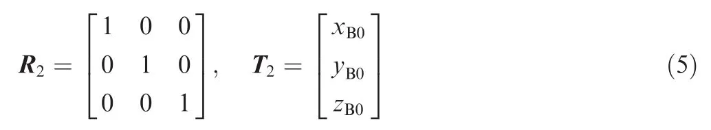
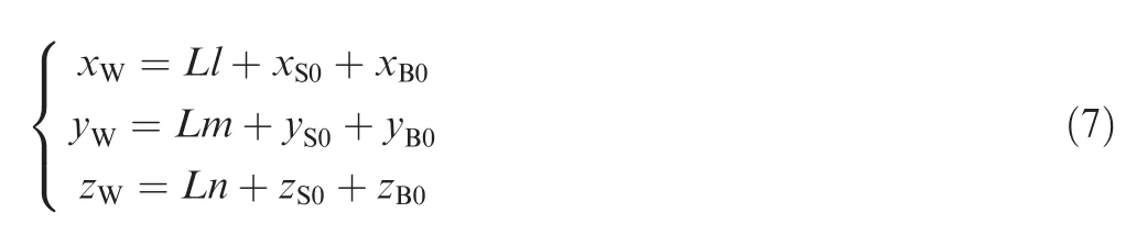
Among them,(xB0,yB0,zB0)signify the coordinates of the originOBinOW-XWYWZW.Thus,the coordinates ofTinOW-XWYWZWdenoted as(xW,yW,zW)can be shown as
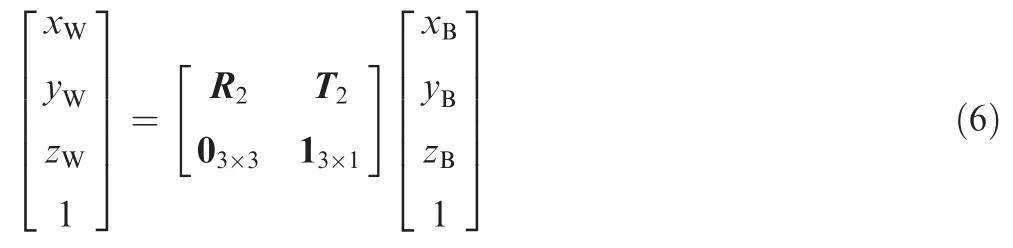
In conclusion,the coordinates ofTin the world coordinate systemOW-XWYWZWcan be derived according to Eqs.(4)and(6),as shown in the following equation:
4.Extrinsic calibration of laser displacement sensor
Generally,there are two types of sensor calibration:One is intrinsic and the other extrinsic.The former involves correction of the optical and structural parameters of a sensor;whereas,the latter is concerned with its attitude and position.The extrinsic calibration problem in this application is specifically defined as the determination of the relationship between the 1D output of a sensor and the 3D coordinates of a light spot,which needs to achieve the unit direction vector of the laser beam and the coordinates of its zero point.Currently,off-the-shelf laser displacement sensors are readily available,which have already been intrinsically calibrated by manufactures before being shipped to customers.Consequently,only extrinsic calibration needs to be executed by customers if a sensor is mounted on 3D scanning equipment.
4.1.Calibration model
As the output of the laser sensor is a 1D data while the measured data must be given in 3D expression in the world coordinate system,a calibration model must be established.The output of the laser sensor denotes just the distance between the zero pointOSof the laser beam and the light spotT,as shown in Fig.2.Thus,in order to derive the 3D coordinates ofT,the unit direction vector of the laser beam needs to be determined,which can be expressed as(l,m,n).As can be seen in Fig.2,in the sensor coordinate system denoted asOS-XSYSZS,the spatial coordinates ofTcan be represented as(Ll,Lm,Ln).
For the purpose of determining the unit direction vector of the laser beam,a metallic sphere utilized for extrinsic calibration is fixed on the platform of the CMM,and an optimization method based on the non-linear least squares algorithm is developed in the paper.
As can be seen in Fig.4,at the beginning of the calibration procedure,the laser sensor is at ‘Position 1” and projects a laser beam onto the surface of the metallic sphere,which forms a light spotP.Generally considered,the zero point of the laser beam noted asOSis on the laser beam and the output of the laser sensor atOSis zero.Consequently,the output of the laser sensorLexpresses the distance between the light spotPand the zero pointOS.InOB-XBYBZB,the equation of the spherical surface can be expressed as follows if the radius of the sphere isr:

Suppose that the coordinates ofOSinOB-XBYBZBare(x0,y0,z0)and the unit direction vector of the laser beam is(l,m,n).According to the principle of vector algebra,the coordinates ofPinOB-XBYBZBcan be expressed as(x0-Ll,y0-Lm,z0-Ln).AsPis on the spherical surface,its coordinates satisfy the constraint equation of the spherical surface,i.e.,


Fig.4 Diagram of calibration model.
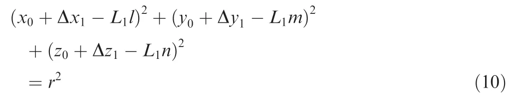
Then,the laser sensor moves to the next position noted as‘Position 2” along with the movements of theX,Y,andZaxes of the CMM.When the laser sensor is moved by the CMM,OW-XWYWZWandOB-XBYBZBkeep fixed,whileOS-XSYSZSis moved with the sensor.Suppose that the incremental movements of theX,Y,andZaxes are Δx1, Δy1and Δz1,respectively.At this time,the zero pointOSmoves toOS1and its coordinates change to(x0+Δx1,y0+Δy1,z0+Δz1).In addition,the laser beam projected onto the spherical surface forms a light spotP1,whose coordinates are(x0+Δx1-L1l,y0+Δy1-L1m,z0+Δz1-L1n)considering that the length of the laser beam changes toL1.According to the same principle,the coordinates ofP1satisfy the constraint equation due to its location on the spherical surface,that is,
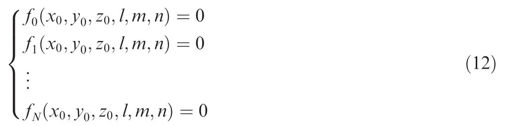
In the same manner,control the motion of the three linear axes of the CMM and record the incremental movement of every axis and the output of the laser sensor,so that several equations of a similar form of Eq.(10)can be derived.Suppose that the CMM movesitimes,and the incremental movements of the three axes for theith movement of the CMM are recorded as Δxi, Δyi,and Δzi,respectively,when compared to ‘Position 1”.As the zero pointOSmoves toOSi,its coordinates also change to(x0+Δxi,y0+Δyi,z0+Δzi).At the moment,the laser beam projected onto the spherical surface forms a light spotPi,whose coordinates can be expressed as(x0+Δxi-Lil,y0+Δyi-Lim,z0+Δzi-Lin)when taking account of the output of the laser sensor noted asLi.Moreover,Piis on the spherical surface,so that its coordinates satisfy the constraint equation of the spherical surface.As a result,an equation group can be employed to contain all the equations derived afterNtimes of movement,which can be expressed as

4.2.Solving method based on optimization
There are 6 unknown parameters in the above equation group containingN+1 equations,which arex0,y0,z0,l,m,andn,while other parameters can be derived from the readings of the three optical scales of the CMM and the output of the laser sensor.Being a multivariate over-determined non-linear equation group,Eq.(11)can be solved by a traditional numerical method,which might be too complicated and tedious.Therefore,a solving method based on a non-linear least squares optimization algorithm is used in the paper,in which the unknown parameters could be solved by an iteration method.In this way,the calibration of the orientation of the laser beam can be completed.The concrete solving process is described as follows.
For simple representation,Eq.(11)can be converted to the following form:
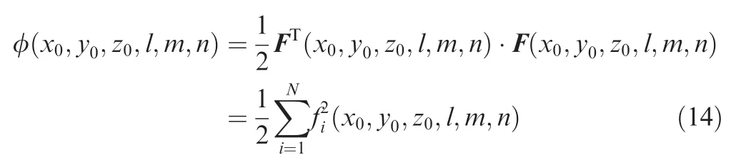
Further,suppose that F(x0,y0,z0,l,m,n)=[f0(x0,y0,z0,l,m,n),f1(x0,y0,z0,l,m,n),...,fN(x0,y0,z0,l,m,n)]T,so the above equation group can be written as

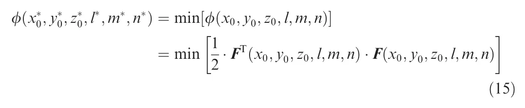
As the function with 6 unknowns noted as F(x0,y0,z0,l,m,n)is non-linear and its general solving process is too sophisticated,it can be transformed into a quadratic functional form,as represented by φ(x0,y0,z0,l,m,n)in the following equation:
Therefore,the minimum value of φ(x0,y0,z0,l,m,n)expressed byandn*is just the least squares solution of Eq.(11),i.e.,
In this case,the problem of solving the non-linear function F(x0,y0,z0,l,m,n)=0 is transformed into the issue of nonlinear least squares optimization.In order to solvem*andn*,the gradient function of φ(x0,y0,z0,l,m,n)should be equal to zero according to the necessary condition of the multivariate function φ(x0,y0,z0,l,m,n)reaching its extreme value,which can be expressed asg(x0,y0,z0,l,m,n)=▽φ
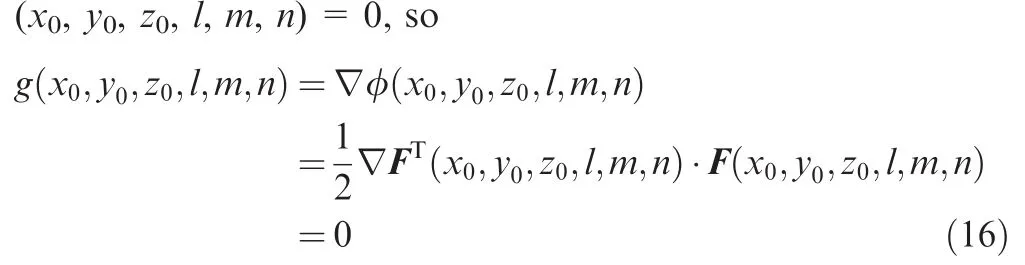
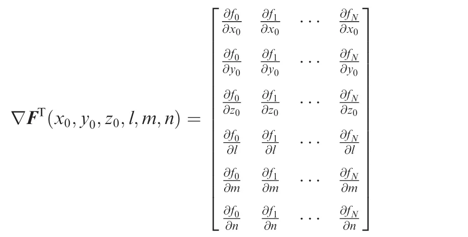
In the above function,
As for the calculation of Eq.(16),the Gauss-Newton iteration method can be utilized.Finally,the coordinates of the zero pointOSexpressed by(x0,y0,z0)and the unit direction vector of the laser beam(l,m,n)can be derived.Thus,the extrinsic calibration of the laser sensor is accomplished,which lays a solid foundation for the following measurement.
4.3.Calibration procedure
The extrinsic calibration involves scanning of a sphere in the working volume of the measuring system whenever a change of the sensor occurs or during the initial system setup.
(1)Adjust the measuring rate of the system,which contains the moving rate of the CMM and the sampling frequency of the laser sensor.Giving consideration to both measuring accuracy and efficiency,the moving rate of the system is set to 5–10 mm/s,while the sampling rate of the laser sensor is set to 40–50 points/s.
(2)Fix the measuring target on the platform of the CMM.According to the normal distribution of the target surface,adjust the orientation of the laser beam to make the direction of the laser beam to be parallel or approximately parallel to the normal direction of the target surface.Then,fix the metallic sphere used for calibration on the platform without any special adjustment,too.
(3)Begin to calibrate the spatial orientation of the laser sensor.Control the motions of the three linear axes of the CMM to make the distance between the laser sensor and the metallic sphere in the measuring range of the sensor,and then record the readings of optical scales of the three axes of the CMM at this time as(X0,Y0,Z0)and the length of the laser beam noted asL.
(4)Plan the motion path of the calibration procedure.In order to improve the calibration accuracy,the motion path of the laser sensor should contain more than three different spatial lines.Accordingly,control the CMM to make the sensor move along the path and record the readings of the axes of the CMM as(Xi,Yi,Zi)and the corresponding output of the laser sensor asLi.Afterwards,compute the increments of the readings at every point as Δxi=Xi-X0,Δyi=Yi-Y0,and Δzi=Zi-Z0.Then,put those values in Eq.(11)to calculate parametersx0,y0,z0,l,m,andn.
(5)Based on the calibration results,scan the target surface using the laser sensor after calibration,and then transform the measured data into the world coordinate systemOW-XWYWZWso as to execute the sequent process.
5.System configuration
In the paper,a CMM named as Pearl from Beijing Precision Engineering Institute for Aircraft Industry is applied as the basis of the whole measuring system,as can be seen in Fig.5.As a CMM of moving bridge,its three axes all adopt the grating detection systems from Renishaw Corporation of Britain,whose strokes are 1200,900,and 800 mm,respectively.With the detection systems,the resolution of every axis is 0.1 μm,while the position accuracy is 3 μm.Meanwhile,granite of steady performance is used in the three guides and air cushions of the air bearings in the three axes are all fullyclosed,which can improve the motion stiffness and stationarity of the whole system.
As one of the optical sensors,a laser displacement sensor ILD 1700-20 from Micro-Epsilon Corporation of German is used to acquire the 3D point cloud of a target surface.Based on the principle of optical triangulation reflection,the sensor can realize non-contact measurement from a relatively long distance.Its specific parameters are listed in Table 1.
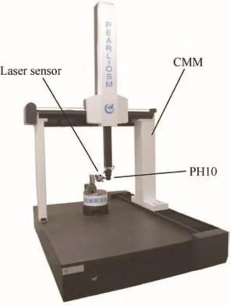
Fig.5 Non-contact optical coordinate measuring system.
With the consideration of the location of the laser device in the sensor,the measuring field of the system can reach 1000 mm×700 mm×700 mm.In addition,in order to make the system more flexible,a probe head pH10 from Renishaw Corporation of Britain is utilized to connect the laser sensor to theZaxis of the CMM,which enables the system measure complicated parts by frequently indexing the laser beam of the sensor approximately consistent with the normal direction of a target surface.As a kind of accessories,pH10 can rotate around the horizontal and vertical axes,both of which are orthogonal at its rotational center.There is an accurate indexing mechanism to make it rotate at a step angle of 7.5°.The angular movement range around the vertical axis is 0–360°,which has 48 positions,while that around the horizontal axis is 0–105°,which has 15 positions.Therefore,pH10 can reach 720 measuring positions in total,which fully meets the requirements of adjusting the orientation of the laser sensor according to a target surface.
To ensure uniform calibration accuracy from all directions,the surface of the calibration target needs to be approximately Lambert.Generally speaking,Lambert surfaces are the best ones for laser sensors,because they always make laser sensors get the same amount of diffusely reflected light from different viewing angles.To achieve the condition of near Lambert,a metallic sphere after being roughly polished is used for calibration,which has good roundness and sphericity,as can be seen in Fig.6.
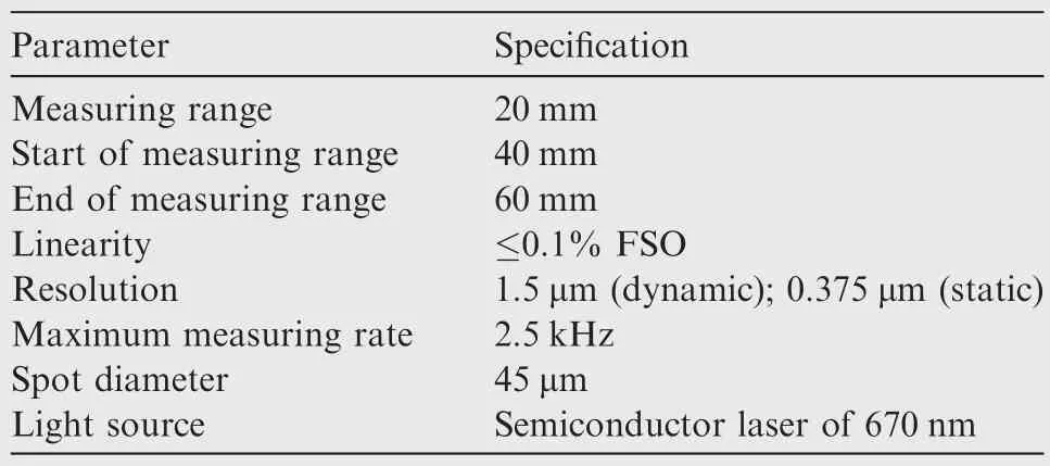
Table 1 Main parameters of ILD 1700–20.
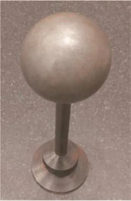
Fig.6 Metallic sphere used for extrinsic calibration.
6.Experimental verification
Digitization of 3D geometric data for a freeform surface and the subsequent reconstruction ofits geometric model are very difficult and complicated tasks.Thus,a sphere with a radius of 50.003 mm is selected to evaluate the effectiveness of the method presented in the paper,which might be the best shape to choose because its surface is analytically defined and can also be used to simulate various features of a spatial surface.
Firstly,before measuring the target sphere,the spatial orientation of the laser sensor should be adjusted.Then,the unit direction vector(l,m,n)and the coordinates of the zero point of the laser beam inOB-XBYBZBdenoted as(x0,y0,z0)at the beginning can be derived through the extrinsic calibration method described above.At the same time,the readings of every grating of the CMM at the beginning of calibration are recorded as(X0,Y0,Z0).
Subsequently,the measuring system after extrinsic calibration can be used to scan the surface of the target sphere,as can be seen in Fig.7.In order to obtain the coordinates ofNi(i=1,2,...,n)on the spherical surface,the coordinates of the zero point of the laser sensor denoted asMiare needed because the sensor coordinate systemOS-XSYSZSmoves with the sensor.Due to the same scale inOW-XWYWZWandOS-XSYSZS,the coordinates ofMican be derived through the initial coordinates ofOSnoted as(x0,y0,z0)and the increments of the three linear gratings of the CMM.As a result,the coordinates ofMican be denoted as(x0+Δxi,y0+Δyi,z0+ Δzi),in which Δxi,Δyi,and Δzidenote the increment of each grating,i.e., Δxi=Xi-X0, Δyi=Yi-Y0,and Δzi=Zi-Z0.Therefore,the coordinates ofNion the target spherical surface could be expressed as(x0+Δxi-lLi,y0+Δyi-mLi,z0+Δzi-nLi),in whichLidenotes the length of the laser beam at theith measuring pointNi.
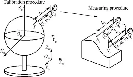
Fig.7 Diagram of measuring procedure.
Finally,adjust the orientation of the laser sensor to scan the target sphere from 10 different directions,in which 200 points are collected each time.The measuring procedure can be seen in Fig.8,and the data collected is shown in a rectangular coordinate system in Fig.9.
Then the derived data can be used to fit the equation of the sphere with the least squares method so as to calculate the fit diameter of the sphere denoted asdi,as can be seen in Fig.10,and the errors can be expressed as δi=di-d,which is shown in Table 2.
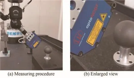
Fig.8 Measuring target sphere.
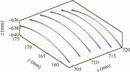
Fig.9 Data collected during experiment.
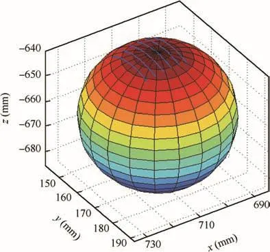
Fig.10 Sphere fitted by the least squares method.
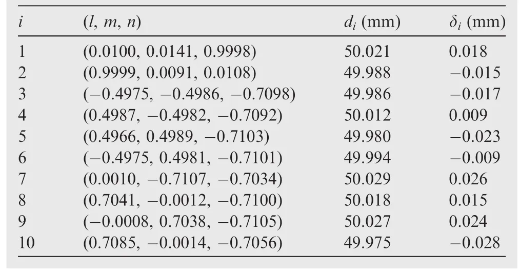
Table2 Measuring resultsand errorsat10 different orientations.
As shown in Table 2,the measuring errors of the fitted diameters are all smaller than 0.03 mm compared with the true values,which manifests the effectiveness of the extrinsic calibration method proposed in the paper.At the same time,the experimental results show the good accuracy and universality of the non-contact coordinate measuring system established,which may be employed in scanning and inspection of the surfaces of blades in the aviation field.
Furthermore,to verify its applicability and generality,several complicated objects are measured by the system established in the paper.As shown in Fig.11,a dental cast is scanned by the system,and the 3D point cloud is presented,as well as the surface generated by it.
7.Further developments
Although a non-contact optical coordinate measuring system has been set up in the paper,as well as the extrinsic calibration method,there is still much improvement to be done before making it commercial equipment and shipping it to customers.Firstly,the calibration accuracy should be inspected by other apparatuses rather than verified by measuring a target with a known dimension,so does the accuracy of the coordinates of a target point.Secondly,in order to derive the complete point cloud of a spatial surface,point clouds from different orientations of the laser sensor need to be spliced together,which demands the research of a splicing method of high precision.Then,as a result of the high sampling frequency of the laser sensor,it needs to study the retrenchment and processing method of large data so as to improve the measuring efficiency.Finally,the way how to use the point cloud collected to fit and evaluate a measured surface should be discussed as a general algorithm which can also be applied in other fields.
8.Conclusions
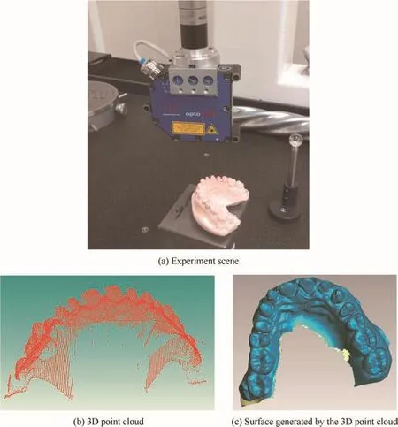
Fig.11 Creation of surface of a dental cast.
For the purpose of measuring the 3D profile of a part with sophisticated features,a novel optical measuring system has been proposed in the paper,which is successfully verified and shows good performance by experiments.In the system,a traditional CMM is used as the platform and the contact probe is replaced by a non-contact laser sensor to realize 3D scanning.In order to transform the 1D output of the laser sensor to the 3D coordinates of a target point,an extrinsic calibration method based on the principle of parameter substitution and non-linear least squares optimization is presented in a detailed way,in which a standard sphere is employed.By solving the over-determined non-linear equation group containing unknown parameters,the direction vector(l,m,n)and the coordinates of the starting point(x0,y0,z0)of the laser beam can be derived,which lays a solid foundation for the subsequent measuring task.Finally,a sphere with a known dimension is measured by the system from 10 different orientations to verify the effectiveness and practicality of the system.Compared with the true values,the errors of the measured results are all smaller than 0.03 mm,which manifests that the calibrating process is facilitating and the calibration result possesses high accuracy.Moreover,the reverse engineering of a dental cast shows the applicability and generality of the system.
Acknowledgements
This research was supported by the National Science and Technology Major Project for ‘High-grade Numerical Control Machine Tools and Basic Manufacturing Equipment”of China(No.2013ZX04001071).
1.Lin XJ,Guo Y,Wu G,Fan NJ,Jiang B,Gao XF,et al.CMM measuring data processing algorithm for blades about the contour measurement.Chin J Sci Instrum2013;34(11):2442–50[Chinese].
2.Lin XJ,Shan CW,Wang ZQ,Shi YY.Measurement techniques of coordinate measuring machine for blade surface of aero-engine.Comput Integr Manuf Syst2012;18(1):125–31[Chinese].
3.Huang HL,Jywe WY,Liu CH,Duan LL,Wang MS.Development of a novel laser-based measuring system for the thread profile of ballscrew.Opt Laser Eng2010;48:1012–8.
4.Li B,Li F,Liu HQ,Cai H,Mao XY,Peng FY.A measurement strategy and an error-compensation model for the on-machine laser measurement of large-scale free-form surfaces.Meas Sci Technol2014;25(1):303–9.
5.Bi C,Zhang Y,Liu Y,Xu CY.Image technology in dimension measurement of high temperature parts.J Chin Soc Mech Eng2014;35(5):355–61.
6.Hsieh TH,Jywe WY,Huang HL,Chen SL.Development of a laser-based measurement system for the scraping workpiece quality.Opt Laser Eng2011;49(8):1045–53.
7.Jiang ZX,Song B,Zhou XD,Tang XQ,Zheng SQ.On-machine measurement of location errors on five-axis machine tools by machining tests and a laser displacement sensor.Int J Mach Tools Manuf2015;95:1–12.
8.Nishikawa S,Ohno K,Mori M,Fujishima M.Non-contact type on-machine measurement system for turbine blade.Proc Cirp2014;24:1–6.
9.Lee RT,Shiou FJ.Multi-beam laser probe for measuring position and orientation offreeform surface.Measurement2011;44(1):1–10.
10.Sun B,Li B.A rapid method to achieve aero-engine blade form detection.Sensors2015;15(6):12782–801.
11.Xie ZX,Zhang CG,Zhang QM,Zhang GX.Modeling and verification of a five-axis laser scanning system.Int J Adv Manuf Technol2005;26(4):391–8.
12.Xie ZX,Zhang CG,Zhang QM.A simplified method for the extrinsic calibration structured-light sensors using a single-ball target.Int J Mach Tool Manuf2004;44(11):1197–203.
13.Xie ZX,Zhang QM,Zhang GX.Modeling and calibration of a structured-light-sensor-based five-axis scanning system.Measurement2004;36(2):185–94.
14.Che CG,Ni J.A ball-target-based extrinsic calibration technique for high-accuracy 3-D metrology using off-the shelf laser-stripe sensors.Prec Eng2000;24(3):210–9.
15.Jorge S,David G,Carlos C,Jose AA,Juan JA.Modeling and calibration technique of laser triangulation sensors for integration in robot arms and articulated arm coordinate measuring machines.Sensors2009;9(9):7374–96.
16.Santolaria J,Pastor JJ,Brosed FJ,Aguilar JJ.A one-step intrinsic and extrinsic calibration method for laser line scanner operation in coordinate measuringmachines.MeasSciTechnol2009;20(4):1–12.
17.Liu SG,Chen C.Calibration of CMM probe based on improved genetic algorithm.J Tianjin Univ2005;38(8):695–700[Chinese].
18.Bi C,Liu Y,Fang JG,Guo X,Lv LP,Dong P.Calibration of laser beam direction for optical coordinate measuring system.Measurement2015;73:191–9.
19.Shiou FJ,Liu MX.Development of a novel scattered triangulation laser probe with six linear charge-coupled devices.Opt Laser Eng2009;47(1):7–18.
20.Zhou FQ,Zhang GJ.Complete calibration of a structured light stripe vision sensor through planar target of unknown orientations.Image Vis Comput2005;23(1):59–67.
21.Nagai Y,Ibaraki S,Nishikawa S.Error calibration offive-axis machine tools by on-machine measurement system using a laser displacement sensor.J Adv Mech Des,Syst,Manuf2014;8(4):1–11.
23 May 2016;revised 27 October 2016;accepted 8 December 2016
Available online 7 June 2017
*Corresponding author.
E-mail address:773721278@qq.com(C.BI).
Peer review under responsibility of Editorial Committee of CJA.
Production and hosting by Elsevier
http://dx.doi.org/10.1016/j.cja.2017.04.016
1000-9361©2017 Production and hosting by Elsevier Ltd.on behalf of Chinese Society of Aeronautics and Astronautics.This is an open access article under the CC BY-NC-ND license(http://creativecommons.org/licenses/by-nc-nd/4.0/).
CMM;
3D scanning;
Extrinsic calibration;
Laser displacement sensor;
Non-linear least squares
杂志排行

CHINESE JOURNAL OF AERONAUTICS的其它文章
- Wake structure and similar behavior of wake profiles downstream of a plunging airfoil
- Self-sustained oscillation for compressible cylindrical cavity flows
- Numerical studies of static aeroelastic effects on grid fin aerodynamic performances
- A new vortex sheet model for simulating aircraft wake vortex evolution
- Linear stability analysis of interactions between mixing layer and boundary layer flows
- Aerodynamic multi-objective integrated optimization based on principal component analysis