Stiffeners layout design of thin-walled structures with constraints on multi-fastener joint loads
2017-11-20JieHOUJihongZHUFeiHEWeihongZHANGWenjieGUO
Jie HOU,Jihong ZHU,Fei HE,Weihong ZHANG,Wenjie GUO
Engineering Simulationamp;Aerospace Computing,The Key Laboratory of Contemporary Design and Integrated Manufacturing Technology,Northwestern Polytechnical University,Xi’an 710072,China
Stiffeners layout design of thin-walled structures with constraints on multi-fastener joint loads
Jie HOU,Jihong ZHU*,Fei HE,Weihong ZHANG,Wenjie GUO
Engineering Simulationamp;Aerospace Computing,The Key Laboratory of Contemporary Design and Integrated Manufacturing Technology,Northwestern Polytechnical University,Xi’an 710072,China
The purpose of this paper is to present an extended topology optimization method for the stiffeners layout design of aircraft assembled structures.Multi-fastener joint loads and manufacturing constraints are considered simultaneously.On one hand,the joint loads are calculated and constrained within a limited value to avoid the failure of fasteners.On the other hand,the manufacturing constraints of the material distribution in the machining directions of stiffeners are implemented by an improved piecewise interpolation based on a beveled cut-surface.It is proven that the objective function is strictly continuous and differentiable with respect to the piecewise interpolation.The effects of the extended method with two different constraints are highlighted by typical numerical examples.Compared with the standard topology optimization,the final designs have clearly shown the layout of stiffeners and the joint loads have been perfectly constrained to a satisfying level.
©2017 Production and hosting by Elsevier Ltd.on behalf of Chinese Society of Aeronautics and Astronautics.This is an open access article under the CC BY-NC-ND license(http://creativecommons.org/licenses/by-nc-nd/4.0/).
1.Introduction
Topology optimization has enhanced the ability for an engineering structural system by redistributing the material in a given design domain to improve the structural performance.Much effort has been made in the least-weight optimization design of aircraft structures.Recent advances and applications of topology optimization have been summarized in the literature surveys by Sigmund and Maute1,Deaton and Grandhi2,Guo and Cheng3,and Zhu et al.4These important achievements continue to motivate further studies on topology optimization and its capabilities in solving more complicated engineering problems.5–7
Thin-walled structures reinforced with stiffeners are widely used in aircraft and aerospace products because of their high carrying capacity and efficiency.The layout of stiffeners greatly determines the structural performance.Research on the stiffeners layout optimization has gained many achievements.For example,in the early works of topology optimization,Cheng and Olhoff8used plate thicknesses as design variables.Stiffeners were realized by increasing the thicknesses of shells elements.This idea was later extended to the layout design of reinforcements of composite materials by Rais-Rohani and Lokits.9Then Krog and Olhoff10proposed the stiffeners configuration optimization with a homogenization method,where the design parameterization was actually based on different configurations of layered microstructures.
The above-mentioned works are direct extensions of standard topology optimization of 2D plates or shells,however at the expense of modeling accuracy of stiffeners.Later,Zhou et al.11introduced additional inequality constraints into the standard density-based topology optimization,which guarantees that the element density in the lower positions is higher than that in the upper ones along the machining directions.In the recent works of Gersborg and Andreasen12and Liu et al.13,a parameterization method was proposed where the height of each column is interpolated with an explicit Heaviside function.In this way,the number of design variables is suppressed and it is simple to be implemented in a standard topology optimization context.Similarly,Zhu et al.14proposed a piecewise linear parameterization to simplify the interpolation for manufacturing constraints and applied it to the design of a stretch-forming die.Besides,there are some other typical works concerning the stiffeners layout design.For example,Lam and Santhikumar15identified stiffeners locations automatically with consideration of constraints on stiffeners’locations and distances.Xia et al.16–18proposed a level-set based optimization of a cast part considering manufacturing constraints.Zuo et al.19combined the MMA(Method of Moving Asymptotes)and wavelets to solve the topology problem with manufacturing constraints.
Another issue discussed in this paper is multi-fastener joint loads.As the aircraft maneuverability improves,the scale of wing spans and the joint loads on the airfoil increase consequently,which put forward higher requirements for the structural design.In assembled aircraft structures,bolts and rivets are widely used as joints to interconnect structural components as integrity.They are sometimes the weakest link of a structure due to the intensity of joint loads,and even act as critical elements at key locations in damage tolerance design.20–23The influence of structural configurations on joint load distribution has been widely studied by engineers and researchers to improve the strength of joints.Typically,the concept of topology optimization has been applied to obtain an even joint load distribution.For example,Chickermane et al.24proposed a topology optimization method for location optimization of fasteners in conjunction with joint load constraints,while connected components remained unchanged.Zhu et al.25extended the standard topology optimization to control joint loads intensities.
In this paper,we further extend the existing studies to deal with the stiffeners layout optimization with joint load constraints.An improved piecewise function is brought into validate the features of stiffeners.The topology optimization is further modified by introducing constraints on multi-fastener joint loads.
2.Basic formulations
2.1.Formulation of joint load constraint
Based on the standard topology optimization with elastic strain energy minimization,the purpose of the extended optimization is to find the material distribution in the design domain satisfying the constraints on the structural volume fraction and joint loads.Here,we use a simple structural system consisting of two components connected with multifastener joints under the load ofFfor demonstration,which is illustrated in Fig.1.
Thereafter,the mathematical formulation of the optimization problem can be expressed as
where η is the vector of the element pseudo-density design variables describing the material distribution in the design domain.Cis the global strain energy.fis the force vector and u is the corresponding nodal displacement vector.K is the global stiffness matrix.Fsis the joint load on thesth fastener.Here,we only consider the shear load on the fasteners.F0is the allowable value for the joint load.mis the number of fasteners.Vis the structural volume andV0is the allowable volume.
The calculation of the joint loads is required in the above topology optimization model.However,many factors shall be taken into account for a precise calculation,such as the relative displacements of hole centers,fastener deformation,conforming contact between fasteners and member plates as well as effects of fastener clamp-up,friction,out of plane deformation,etc.To tackle the extra complexities and computational difficulties in simulating the behaviors of multi-fastener joints,some modeling techniques and optimization schemes have been proposed by Chickermane et al.24,Zhu et al.25,and Ekh and Scho¨n.26In this paper,beam elements are used to model the multi-fastener joints approximately to obtain the joint loads in terms of the design variables.
As the idealized multi-component structural system shown in Fig.2,member plates are modeled by shell elements and the bolt is modeled by a single beam element.The shell elements are placed in the mid-surface of the real structure.The parameters of the beam and shell elements are assigned with the equivalent parameters of the real structure.For a short beam with NodesAandBas shown in Fig.2,the shear load can be calculated as
with
whereEandGare the elastic and shear moduli,respectively.To simulate the behavior of a common fastener such as bolt,rivet,and the like,the beam elements have a circular cross section.I,S,andLdenote the moment of inertia,the cross section area,and the beam length,respectively.Φ is the shear coefficient.γ=10/9 is the shear factor of the cross section.usAxand θsAxare the corresponding nodal displacement and rotation angle of NodeAalongxdirection.Similar definitions are used forusAy,θsAy,usBx,θsBx,usBy,and θsBy.
To simplify the expression,we define the coefficient vectors λsxand λsyas
where the dimensions of λsxand λsyare the same as that of the displacement vector u.
2.2.Formulation of manufacturing constraints for stiffeners
In the extended topology optimization,the stiffeners layout can be described by their heights and widths,which is implemented with a modified piecewise linear parameterization model here.The interpolation is explained as shown in Fig.3.In practice,there are three totally different pseudodensities involved in this model,i.e.,the element height pseudo-density indicating an element’s contribution to the corresponding column’s height,the column pseudo-density indicating the existence of a column,and the element material pseudo-density indicating the element material properties.
Suppose that the size of each element is uniformly 1.The height of theith columnhiappears as an artificial level which is defined as a beveled cut-surface.The elements in a column below the level are assigned as solid and those above as void.Only the elements cut by the level will be interpolated according to the ratio of the solid volume to the void volume,namelye1,e2,ande3in Fig.3.
The interpolation can be expressed as
where ⌊hi⌋is the floor function ofhi.H1,H2,andH3indicate 3 different interpolated areas corresponding toe1,e2,ande3.Niis the total number of elements in theith column.xi(j)indicates the pseudo-density of thejth element in theith column.When ⌊hi⌋equals to 0,the element pseudo-density of the entire column is simply assigned as 0.This will prevent columns with low heights.
Meanwhile,to have a distinct layout of stiffener ribs in the optimized design,the column pseudo-densities suggested by Liu et al.13are used to dominate the existence of an entire column.As a result,for a specificjth element in theith column,this actually defines the element material pseudo-density ηi(j)dominating the element material properties,that is,
wherepis the parameter of the SIMP(Solid Isotropic Material with Penalization)model.ziis theith column’s pseudo-density penalized withqin conformity with the SIMP model.ηi(j)is related to its stiffness matrix Ki(j)by a linear interpolation model.K0is the stiffness matrix of a solid element.pandqare consistently assigned as 3 in this paper.
As a result,the two sets of design variables are actually designed in the topology optimization,i.e.,a column’s height variablehiand its pseudo-density variableszi.
3.Sensitivity analysis
3.1.Sensitivity of strain energy
The sensitivities of the objective function,i.e.,the global strain energyCwith respect to the two different design variables,are derived by chain rules as
Here,the derivatives of the element elastic strain energy with respect to the column’s pseudo-densities can be easily obtained according to the interpolation model,which is not provided here.Then,we consider the sensitivity with respect to the column’s height variable,where only three elements around the cut-surface are interpolated,i.e.,
As the interpolation function consists of the piecewise functions,there can be some possible discontinuities.Here,we investigate the left and right limits whenhiis an integer.As shown in Fig.4,the related elements shift from{xi(j-1),xi(j),xi(j+1)}to{xi(j),xi(j+1),xi(j+2)}whenhiis an integerjfor example.
According to Eq.(8),the left derivative with respect tohican be expressed as and the right derivative can be expressed similarly as
As a result,we can draw the conclusion that the linear interpolation using a beveled cut-surface can strictly ensure the continuity and convergence of the optimization under all circumstances.Besides,it also holds the advantage of simplicity compared with the complex and highly nonlinear Heaviside interpolation.
3.2.Sensitivity of joint load constraint
For thesth fastener,the sensitivity of the joint load with respect to an arbitrary variable ξ reads
Choose λsthat
Based on the finite element equilibrium equation,Eq.(11)can be further written as
The above expression can be derived according to a standard adjoint method with the following notation:
Notice that the stiffness matrix K is symmetric.u*can be interpreted as the displacement vector related to the adjoint load vector λsapplied on the structure and solved by one extra finite element analysis.The substitution of Eq.(14)into Eq.(13)gives rise to
In the above equation,the derivative of the load vector is zero when only design-independent loads are applied to the structure.Here,we assign ξ as design variableshiandzirespectively.According to the interpolation model in Eq.(6),the derivatives of the joint load with respect to the design variables can be expressed separately as
In practice,the number of fasteners can be enormous in an engineering structure.It is more accurate to control the joint loads separately.However,sensitivity analyses of the joint loads will be computationally expensive due to the additional finite element analysis for a large number of joint load constraints.A similar problem draws attention in stress-based topology optimization as stress is evaluated and constrained below a prescribed limit in each element.To remedy the drawback,aggregation methods combine all local stresses into one or several Kreisselmeier-Steinhauser(KS)orp-norm global functions.27–29Thep-norm of the joint loadsFnormreads
wherenis the number of joints and pn is thep-norm factor.
Recently,different aggregation strategies have been proposed.For example,the active set approach30aggregates active constraints into one set,which highly reduces the number of stress constraints.Le et al.31introduced an adaptively updatedp-norm aggregation method,which can precisely approximate the maximum local stress.A clustered method32was proposed as a compromise between global and local methods,in which constraints were aggregated into several clusters.This method was proven to be efficient and robust by numerical examples,but the results strongly depended upon the number of clusters.Luo33,34proposed enhanced aggregation methods based on a KS function with good approximation accuracy.
4.Numerical examples
In the following sections,three numerical examples are presented to illustrate the efficiency and validity of the proposed optimization method.The optimization algorithm GCMMA(Globally Convergent Method of Moving Asymptotes35)implemented in the general-purpose design platform Boss-Quattro36is used for all the examples.Manufacturing constraints are inherently implemented by linear interpolation when setting up the finite element model and no further treatment is needed.
The optimized topologies change with different initial configurations or optimization parameters.This phenomenon is observed and denoted as local minima.37The fundamental cause of the local minima lies in the non-convexity of the objective function and the constraint of topology optimization.As a result,the optimized topologies obtained by gradientbased algorithms(here,GCMMA)are always some local minima.A continuation method was proposed by Jog and Haber38and Sigmund.39It takes the global information into account for optimization and ensures more ‘global”convergence.In this paper,a sensitivity filter technique with continuation is used with the final filter radius being 3 times of the average element size to avoid checkerboards patterns.It is notable that the optimized results are still the local minima.
4.1.C-section cantilever beam
A C-section cantilever beam connected to two sheets with 198 fasteners sketched in Fig.5 is optimized here.The fasteners are parallel arranged in 6 rows.The 2 mm thick web of the C-beam is assigned as the base plane of the stiffeners.The C-beam and the sheets are meshed with 4-node shell elements.The design domain is a 70 mm×20 mm×10 mm block and is meshed with 8-node brick elements with a uniform size of 1 mm.The elastic modulus is 210 GPa and the Possion’s ratio is 0.3.A point load off=1000 N is applied at the lower right node of the C-beam web shell elements.
Firstly,a standard topology optimization design is presented in Fig.6 along with the joint loads.For brevity,only the maximum load among different rows in one numbered station is plotted which is employed throughout the paper.The objective is to minimize the elastic strain energy using maximum 15%of the total material.In the optimized result,the elastic strain energy is 71.71 J and the maximum joint load arises on the 1st fastener in Row A with a value of 145 N.Without any manufacturing constraints,the material tends to form a layer of shell hanging over the C-beam web.Theoretically,it is the stiffest topological configuration.However,the optimized result satisfies the stiffness requirement but hardly offers any references for stiffeners design.
To take full advantages of the stiffeners,the standard topology optimization is extended with the manufacturing constraint.From the view of manufacturability,the directionTperpendicular to the web of the C-beam is defined as the machining direction.According to the manufacturing constraint fomulation,the number of design variables is directly reduced from 14000 to 2800.The optimized result is presented in Fig.7.The elastic strain energy of the optimized result is 86.24 J,which is 20.3%higher than that without the manufacturing constraint.The maximum joint load arises on the first fastener in Row D with a value of 206.1 N.The manufacturing constraint compels the high-densityelementstoappearbelowthelow-densityelements.Thus along the maching direction,the elemental densities decrease monotonically,which finially leads to a clear layout of stiffeners.The colour map indicates the variation of the columnheights. It can be seen that the web is reinforced in the main load-carrying path to bear the external load,and near the fixed end,the reinforced ribs are lower in heights.
This test illustrates the effectiveness of the proposed method in stiffeners design.Following the idea of Zhu et al.25,a joint load constraint of 160 N is then introduced in the former topology optimization problem,additionally with the manufacturing constraint.
The optimized design with the joint load constraint is also shown in Fig.7.The strain energy is 96.99 J,which increases 12%compared with the previous one.The maximum joint load arises on the first fastener in Row D with a value of 160 N,satisfying the design constraint and decreases 22.3%compared with the previous one.The stiffeners layout shows a great difference.More material gathers around the fixed end to reinforce the cantilever and the fasteners with large joint loads.Some newly formed supporting branches relieve the intensity of the joint loads.In contrast,the structural branches near the external load are weakened,which leads to a decrease of the overall stiffness.
To have a better understanding of the mechanism that how the joint load constraint affects the structure design,the principal stresses in the stiffener ribs are plotted in Fig.8.In Fig.8(a),the material is attached to the upper and lower flanges,improving the bending stiffness of the C-beam.In Fig.8(b),the material tends to reinforce the flange and the web while maintaining the stiffness near the fixed end to coordinate the displacement with the extra joint load constraint.
4.2.Plate structure with distributed load
As shown in Fig.9,a plate structure with distributed load is considered.In order to maintain the consistency of the structure,a 1 mm thick layer is defined as the base plane of the stiffeners and reserved as a non-design domain.The normal of the base plane pointing at the design domain is defined as the machining direction.The size of the design domain is 50 mm×20 mm×5 mm and meshed with 8-node brick elements.The elastic modulus is 210 GPa and the Poisson’s ratio is 0.3.The plate is clamped on one side and supports a layer of skin on top.The plate and the skin are joined with 36 fasteners in 3 rows that are simulated by beam elements.The pressure loadpeapplied on the skin is 10 MPa.
Topology optimization is carried out to minimize the elastic strain energy with a 30%volume fraction.Without any further consideration of manufacturability,the optimized topology seems to be a box-like structure as shown in Fig.10.The elastic strain energy of the result is 6.59 J.The suspended layer is connected to the base plane by several supports.High-density elements are on the top of void elements along the machining direction.To obtain the layout of the stiffeners,the manufacturing constraint is firstly applied and then a joint load constraint of 2300 N is applied additionally.The details of the two optimized results are listed in Table 1.The elastic strain energy is respectively 7.42 J and 7.75 J.The maximum joint load is reduced from 2548 N to 2300 N.The 4.5%loss of glo-bal stiffness obtains a reduction of 248 N in the maximum joint load in return.
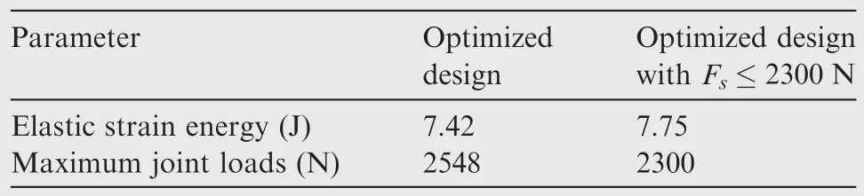
Table 1 Comparison of optimized results.
The joint load distributions are presented in Fig.11.According to the symmetry of the structure,only the joint loads in the fasteners of Rows A and B are plotted.The maximum joint load is on the first fastener in Row B.Clearly,the joint loads in Fig.11(b)satisfy the design constraints.
Obviously,both optimized designs show a distinct layout of stiffeners with a proper height and width.In Fig.11(a),a strong root arises near the clamped side and extends in three branches towards the free side.The position of each rib branch corresponds to the fasteners.Apparently,this configuration makes the shortest load-carrying path and the best stiffness.With the introduction of the joint load constraint,the structure in Fig.11(b)shows four separated branches avoiding the positions of the fasteners.The structure around the fasteners is weakened to coordinate the deformation of the skin and the support.The overall stiffness is weakened as well.
It is also noted that a severe constraint on joint loads will sometimes banish the material around the fasteners with maximum joint loads.Fig.12 shows the optimized configuration with different joint load constraints.When the joint load constraint is relaxed to 2500 N,a slight reduction of compliance is obtained.Solid structures appear around the joints.As the constraint decreases from 2400 N to 2000 N,there exists less material around the joints with maximum joint loads.Meanwhile,the structural compliance rises dramatically,which indicates a great loss in stiffness.
4.3.Design of reinforced wing rib stiffeners
In this section,the established method is carried out in the aircraft wing rib design.In an aircraft wing box,there are skin panels,stringers,spars,and wing box ribs composing the global structure.Ribs are used to maintain the wing contour.16A basic wing rib as shown in Fig.13 is extracted from the wing structure and applied with equivalent loads and boundary conditions derived from the entire structure.The direction perpendicular to the rib is defined as the machining direction.The size of the wing rib is also sketched in Fig.13.A design domain is generated based on the web and meshed with 8-node brick elements.Naturally,the height of the flange defines the upper boundary as 50 mm.The elastic modulus is 210 GPa and the Poisson’s ratio is 0.3.
The optimization is to minimize the elastic strain energy with a 15%permissible material usage.In Fig.14(a),the optimized result with the manufacturing constraint is presented.Fig.14(b)shows the result with an additional joint load constraint of 40 N.The configurations of the stiffeners in these two designs are generally similar in spite of some details.Four main branches enforce the web aside the manholes.Several detailed enforcement structures are distributed along the upper and lower flanges corresponding to the fasteners.The main difference between these two configurations is near the lower left side of the web,i.e.,the region connected to the fasteners with maximum joint loads,where more material gathers around to ameliorate the joint load distribution.The maximum joint load decreases from 56.9 N to 40 N,with a magnitude of 29.7%.All the joint loads have been perfectly constrained to the desired level.The strain energy increases from 58542.9 J to 64040.9 J,with a magnitude of 9.4%.
5.Conclusions
In this paper,we propose an extended topology optimization model using a manufacturing constraint based on an improved piecewise linear interpolation and a constraint on fasteners’joint loads simultaneously.The joint load intensities are ameliorated by redistributing the stiffeners.
Compared with the standard topology optimization design,the manufacturing constraint generates stiffener-like directional material distributions,and the joint load constraint redistributes the layout of the stiffeners to support the fasteners properly.It is shown by numerical examples that proper stiffener layout design can significantly reduce joint loads with a decrease of global stiffness.
Acknowledgements
This work is supported by National Natural Science Foundation of China(Nos.11432011,11620101002),National key research and development program of China (No.2017YFB1102800),Key Research and Development Program of Shaanxi,China(No.S2017-ZDYF-ZDXM-GY-0035).
1.Sigmund O,Maute K.Topology optimization approaches.Struct Multidiscip Opt2013;48(6):1031–55.
2.Deaton JD,Grandhi RV.A survey of structural and multidisciplinary continuum topology optimization:Post 2000.Struct Multidiscip Optim2014;49(1):1–38.
3.Guo X,Cheng GD.Recent development in structural design and optimization.Acta Mech Sin2010;26(6):807–23.
4.Zhu JH,Zhang WH,Xia L.Topology optimization in aircraft and aerospace structures design.Arch Comput Method Eng2016;23(4):595–622.
5.Vu NA,Lee JW,Le TPN,Nguyen STT.A fully automated framework for helicopter rotor blades design and analysis including aerodynamics,structure,and manufacturing.Chinese Journal of Aeronautics2016;29(6):1602–17.
6.Zhao K,Gao ZH,Huang JT,Li Q.Aerodynamic optimization of rotor airfoil based on multi-layer hierarchical constraint method.Chinese Journal of Aeronautics2016;29(6):1541–52.
7.Koreanschi A,Gabor OS,Acotto J,Brianchon G,Portier G,Botez RM,et al.Optimization and design of an aircraft’s morphing wing-tip demonstrator for drag reduction at low speed,Part I-Aerodynamic optimization using genetic,bee colony and gradient descent algorithms.Chinese Journal of Aeronautics2017;30(1):149–63.
8.Cheng KT,Olhoff N.An investigation concerning optimal design of solid elastic plates.Int J Solids Struct1981;17(3):305–23.
9.Rais-Rohani M,Lokits J.Reinforcement layout and sizing optimization of composite submarine sail structures.Struct Multidiscip Optim2007;34(1):75–90.
10.Krog LA,Olhoff N.Optimum topology and reinforcement design of disk and plate structures with multiple stiffness and eigenfrequency objectives.Comput Struct1999;72(4):535–63.
11.Zhou M,Shyy YK,Thomas HL.Topology optimization with manufacturing constraints.Proceedings of the 4th world congress of structural and multidisciplinary optimization;2001;Dalian,China.Dalian:International Society for Structural and Multidisciplinary Optimization;2001.
12.Gersborg AR,Andreasen CS.An explicit parameterization for casting constraints in gradient driven topology optimization.Struct Multidiscip Optim2011;44(6):875–81.
13.Liu ST,Li QH,Chen WJ,Hu R,Tong LY.H-DGTP—A Heaviside-function based directional growth topology parameterization for design optimization of stiffener layout and height of thin-walled structures.StructMultidiscipOptim2015;52(5):903–13.
14.Zhu JH,Gu XJ,Zhang WH,Beckers P.Structural design of aircraft skin stretch-forming die using topology optimization.J Comput Appl Math2013;246(5):278–88.
15.Lam YC,Santhikumar S.Automated rib location and optimization for plate structures.Struct Multidiscip Optim2003;25(1):35–45.
16.Xia Q,Shi TL,Wang MY,Liu SY.A level set based method for the optimization of cast part.Struct Multidiscip Optim2010;41(5):735–47.
17.Xia Q,Shi TL.Optimization of structures with thin-layer functional device on its surface through a level set based multiple-type boundary method.Computer Methods in Applied Mechanics and Engineering2016;311:56–70.
18.Xia Q,Shi TL.Topology optimization of compliant mechanism and its support through a level set method.Computer Methods in Applied Mechanics and Engineering2016;305:359–75.
19.Zuo KT,Chen LP,Zhang YQ,Yang JZ.Manufacturing-and machining-based topology optimization.Int J Adv Manuf Technol2006;27(5):531–6.
20.Chintapalli S,Elsayed MSA,Sedaghati R,Abdo M.The development of a preliminary structural design optimization method of an aircraft wing-box skin-stringer panels.Aerosp Sci Technol2010;14(3):188–98.
21.Niu MCY.Airframe structural design—Practical design information and data on aircraft structure.Burbank(CA):Conmilit Press;1988;p.247–302.
22.Barrett RT.Fastener design manual.Washington,D.C.:NASA;1990.Report No.:NASA-RP-1228.
23.Wang BZ.Aircraft design manual 10:Structural design.3rd ed.Beijing:Aviation Industry Press;2000,p.42-78[Chinese].
24.Chickermance H,Gea HC,Yang RJ,Chuang CH.Optimal fastener pattern design considering bearing loads.Struct Optim1999;17(2):140–6.
25.Zhu JH,Hou J,Zhang WH,Li Y.Structural topology optimization with constraints on multi-fastener joint loads.Struct Multidiscip Optim2014;50(4):561–71.
26.Ekh J,Scho¨n J.Finite element modeling and optimization of load transfer in multi-fastener joints using structural elements.Compos Struct2008;82(2):245–56.
27.Yang RJ,Chen CJ.Stress-based topology optimization.Struct Multidiscip Optim1996;12(2):98–105.
28.Duysinx P,Bendsøe MP.Topology optimization of continuum structures with local stress constraints.Int J Numer Meth Eng1998;43(8):1453–78.
29.Gao HH,Zhu JH,Zhang WH,Zhou Y.An improved adaptive constraint aggregation for integrated layout and topology optimization.Comput Methods Appl Mech Eng2015;289:387–408.
30.Duysinx P,Sigmund O.New developments in handling stress constraints in optimal material distributions.Proceedings of 7th AIAA/USAF/NASA/ISSMOsymposiumonmultidisciplinary design optimization;1988;Saint Louis(MO).Reston(VA):AIAA;1998.
31.Le C,Norato J,Bruns T,Ha C,Tortorelli D.Stress-based topology optimization for continua.Struct Multidiscip Optim2010;41(4):605–20.
32.Holmberg E,Torstenfelt B,Klarbring A.Stress constrained topology optimization.Struct Multidiscip Optim2013;48(1):33–47.
33.Luo YJ,Kang Z.Topology optimization of continuum structures with Drucker-Prager yield stress constraints.Comput Struct2012;90(1):65–75.
34.Luo YJ,Wang MY,Kang Z.An enhanced aggregation method for topology optimization with local stress constraints.Comput Methods Appl Mech Eng2013;254:31–41.
35.Svanberg K.The method of moving asymptotes—A new method for structural optimization.Int J Numer Meth Eng1987;24(2):359–73.
36.Radovcic Y,Remouchamps A.BOSS QUATTRO:An open system for parametric design.Struct Multidiscip Optim2002;23(2):140–52.
37.Sigmund O,Petersson J.Numerical instabilities in topology optimization:A survey on procedures dealing with checkerboards,mesh-dependencies and local minima.Struct Optim1998;16(1):68–75.
38.Jog CS,Haber RB.Stability offinite element models for distributed-parameter optimization and topology design.Comput Methods Appl Mech Eng1996;130(3–4):203–26.
39.Sigmund O.On the design of compliant mechanisms using topology optimization.Mech Struct Mach1997;25(4):493–524.
6 June 2016;revised 18 October 2016;accepted 22 January 2017
Available online 7 June 2017
*Corresponding author.
E-mail address:jh.zhu@nwpu.edu.cn(J.ZHU).
Peer review under responsibility of Editorial Committee of CJA.
Production and hosting by Elsevier
http://dx.doi.org/10.1016/j.cja.2017.05.005
1000-9361©2017 Production and hosting by Elsevier Ltd.on behalf of Chinese Society of Aeronautics and Astronautics.
This is an open access article under the CC BY-NC-ND license(http://creativecommons.org/licenses/by-nc-nd/4.0/).
Joint load constraint;
Manufacturing constraint;
Stiffeners;
Thin-walled structures;
Topology optimization
杂志排行

CHINESE JOURNAL OF AERONAUTICS的其它文章
- Wake structure and similar behavior of wake profiles downstream of a plunging airfoil
- Self-sustained oscillation for compressible cylindrical cavity flows
- Numerical studies of static aeroelastic effects on grid fin aerodynamic performances
- A new vortex sheet model for simulating aircraft wake vortex evolution
- Linear stability analysis of interactions between mixing layer and boundary layer flows
- Aerodynamic multi-objective integrated optimization based on principal component analysis