Optimal deployment schedule of an active twist rotor for performance enhancement and vibration reduction in high-speed flights
2017-11-20YoungYOUSungJUNGChangKIM
Young H.YOU,Sung N.JUNG,Chang J.KIM
Department of Aerospace Information Engineering,Konkuk University,Seoul 05019,Republic of Korea
Optimal deployment schedule of an active twist rotor for performance enhancement and vibration reduction in high-speed flights
Young H.YOU,Sung N.JUNG*,Chang J.KIM
Department of Aerospace Information Engineering,Konkuk University,Seoul 05019,Republic of Korea
The best active twist schedules exploiting various waveform types are sought taking advantage of the global search algorithm for the reduction of hub vibration and/or power required of a rotor in high-speed conditions.The active twist schedules include two non-harmonic inputs formed based on segmented step functions as well as the simple harmonic waveform input.An advanced Particle Swarm assisted Genetic Algorithm(PSGA)is employed for the optimizer.A rotorcraft Computational Structural Dynamics(CSD)code CAMRAD II is used to perform the rotor aeromechanics analysis.A Computation Fluid Dynamics(CFD)code is coupled with CSD for verification and some physical insights.The PSGA optimization results are verified against the parameter sweep study performed using the harmonic actuation.The optimum twist schedules according to the performance and/or vibration reduction strategy are obtained and their optimization gains are compared between the actuation cases.A two-phase non-harmonic actuation schedule demonstrates the best outcome in decreasing the power required while a four-phase non-harmonic schedule results in the best vibration reduction as well as the simultaneous reductions in the power required and vibration.The mechanism of reduction to the performance gains is identified illustrating the section airloads,angle-of-attack distribution,and elastic twist deformation predicted by the present approaches.
©2017 Chinese Society of Aeronautics and Astronautics.Production and hosting by Elsevier Ltd.This is anopenaccessarticleundertheCCBY-NC-NDlicense(http://creativecommons.org/licenses/by-nc-nd/4.0/).
1.Introduction
A rotor’s flow field in forward flight is complicated due to the rotation and movement of the rotor in the edgewise direction.1In high-speed conditions,the tip regions in the advancing side are under high dynamic pressure and transonic effect while the retreating side is confronted with low dynamic pressure and retreating blade stall,resulting in a loss of symmetry laterally.Due to the asymmetric nature of the flows,a rotor is prone to high vibration and noise as well as low performance characteristics compared with a fixed-wing counterpart.To overcome the disadvantages of a rotor,many active control concepts and mechanisms have been devised as potential engineering solutions.Among these methods,the Active Twist Rotor(ATR)concept offers such advantages as follows:no hydraulic power systems and separate mechanical parts are needed since the rotor blades are directly twisted using the induced-strain actuation concept while the actuator itself serving as a part of the blade structure.The ATR was pioneered by Chen and Chopra2using direct strain components of embedded piezoceramic elements.Detailed discussion of the ATR and its development can be found in Chopra’s work.3Thakkar and Ganguli4,5and Pawar and Jung6used induced-shear based piezoceramic actuation to benefit the ATR.
For the twist actuation,most of the previous research has been performed using harmonic-based functions introduced into the rotor blade individually.In this case,the amplitude and phaseofspecificactuation frequenciesarevaried arbitrarily for the twist control.The representative work is the NASA/Army/MIT rotor tested in the NASA Langley Transonic Dynamics Tunnel.7,8Either of 3/rev to 5/rev(per revolution)actuation was applied to the actuator materials embedded in the blade to reduce vibration and Blade-Vortex Interaction (BVI)noise.Yeo9investigated the relative performance of several active control concepts including the ATR.A 2/rev harmonic input was applied to enhance the rotor performance.Changes in the rotor lift-to-drag ratio were traced to quantify the actuator gains.Recently,an international joint program called Smart Twisting Active Rotor(STAR)was launched to realize the benefit of the ATR concept for performance improvement,vibration reduction,and noise alleviation of a scaled Bo-105 rotor.10In a numerical simulation,up to 5/rev harmonic inputs were applied to a variety offlight conditions.The preliminary study showed good potential in reaching the goals though the predicted outcomes should be verified by performing a series of wind tunnel tests.The control inputs used in the above studies are simple in nature and relatively easy to apply;however,the overall gain is limited since the control waveforms are generally not optimized and do not reflect the operational environments that a rotor faces in diverse flight regimes.
A more generic and non-harmonic form of twist inputs has been found growing interests to further benefit the smart rotor concept.In this actuation,arbitrary waveforms based on a step or saw-type function are generated to activate a rotor.Fogarty et al.11used a step input to examine the BVI noise characteristic by the actuation of an Macro Fiber Composites(MFC)actuator embedded in portions of an Apache AH-64A blade.The step input was characterized by the rotor’s azimuthal location to the start,duration,and magnitude of the actuation.A noise reduction up to 10 dB was reached with the nonharmonic twist control.It was indicated that the noise reduction gain was highly dependent on the choice of the initial azimuthal location and the duration of the actuation profile.Jain et al.12investigated several on-blade active controls including the active twist control for improving the rotor performance.An advancing-side-only actuation with a 2/rev harmonic input was adopted in the twist control.The proposed waveform was found to be effective in improving the rotor performance particularly in a high-speed flight regime.
Recently,You et al.13conducted a preliminary optimization to search for the best twist deployment schedules using a modern evolutionary algorithm.14The goal was to improve performance and to reduce vibration in diverse flight conditions.A rotorcraftComputationalStructuralDynamics(CSD)analysis code CAMRAD II15was employed for the aeromechanics analysis.Five different actuation scenarios including two harmonic and three non-harmonic waveforms were considered for the twist inputs.Promising results with increased gains were obtained;however,only the CSD approach was conducted in the analysis.You and Jung16have refined their investigation by focusing on non-harmonic actuations that may reflect a rotor’s operational environments.The CSD analysis was loosely coupled with a Computational Fluid Dynamics(CFD)code to verify the optimum results and to explain the physics leading to the improvement by the twist control.The flight regime was confined to a low-speed descending flight.
The present study focuses on high-speed forward flights where both vibration and performance have been significant concerns during the operation of a rotorcraft.It is aimed at finding the best actuation scenarios for performance improvement and/or vibration reduction of a rotor using specified nonharmonic ATR inputs taking advantage of the global search algorithm adopted previously.Either two-phase or fourphase segmented non-harmonic waveforms along with a simple harmonic input are introduced.The optimum results obtained using the harmonic input are verified against those by a parameter sweep study computed sparsely over the whole design space.Next,the best twist actuation schedules characterized for vibration and/or performance are sought using the proposed non-harmonic waveform profiles.A CFD/CSD coupled analysis is carried out to investigate the mechanism of reduction in power required with the introduction of twist control in a high-speed flight regime.
2.Analytical methods
2.1.Active twist scenarios
For improved performance of a rotor,the actuation schedules should be determined considering the rotor’s operational environments in specific flight conditions.Fig.1 shows respective ATR scenarios adopted in the present study.As is depicted,the rotor disk is split into a number of zones under different control laws with respect to the actuation scenarios.The shaded regions indicate the zones with the twist application whereas the blank region indicates no actuation region.Traditionally,Single Harmonic(SH)actuation such as the one presented in Fig.1(a)has been widely used for its simplicity in shape and ease of operation with the function.In this schedule SH,each blade is actuated harmonically over the whole rotor disk area(without pause)as
whereTis the twisting moment,ψ the rotor’s azimuth angle,Athe amplitude of the twisting couple,nthe harmonic number,and φ the phase angle.
Given the harmonic actuation Case SH as a reference,two other ATR scenarios formed based on a step(non-harmonic)function are introduced to effectively counter the complicated aerodynamic fields apparent in a forward flight and their interactions with other disciplines(e.g.,vibration and noise).Cases NHa and NHb shown in Fig.1 are the proposed nonharmonic actuation profiles.For Case NHa(Fig.1(b)),both the advancing and retreating sides of the rotor disk are placed under different control laws with appropriate waveform inputs.This two-phase scenario is tailored to the aerodynamic environment of a helicopter rotor particularly in a high-speed forward flight where the advancing side undergoes high dynamic pressure while the retreating side suffers from the reversed flow and the stall.In addition,Case NHb(Fig.1(c))is capable of considering each quadrant of the rotor separately.This four-phase scenario is suited to counter BVI-like events in which interacting vortices are generated originally in the second or third quadrant while BVI occurs in the first and fourth quadrants referenced from the rear of the rotor disk.16For non-harmonic actuations,the surface actuators are activated under constant voltage inputs during the designated intervals(shaded regions)in the rotor’s azimuthal plane to modify the rotor’s incidence angles for altering local aerodynamics and thereby alleviating hazardous interaction events unless otherwise unavoidable.
2.2.Actuator model in rotorcraft aeromechanics analysis
A rotorcraft CSD code CAMRAD II15is used to analyze the rotor.The blade motion is represented by three translational(axial,flap,and lead-lag)and three rotational Degrees of Freedom(DOFs)resulting in 15 DOFs per beam element.A total of 18 nonlinear beam finite elements distributed along the span length are used to model the blade.The ONERA-EDLIN unsteady aerodynamic theory along with C81 airfoil table look-up is used for the aerodynamic loads acting on blades.In CSD analysis,a rolled-up free wake or prescribed wake representation is used to obtain the rotor-induced fields.The rolled-up vortex wake model is based on the feature that a tip vortex forms at the blade tip and convects to the flow field behind the rotor.Given the feature that tip vortices in highspeed flights convect aft and below the rotor disk rather quickly and the wake geometry is well-preserved,the prescribed wake model is adopted in the present CSD analysis.This feature will be discussed later in a separate section.Only an isolated rotor condition is considered to simplify the analysis.
The active twist model is facilitated in CAMRAD II by applying torsional moments with equal and opposite magnitudes at both extremities over the actuator zone of the blade.Fig.2 shows the schematic of the ATR control under the application of a torsional couple,in which θTis the active twist angle.It is assumed that the MFC actuator is embedded in the blade skin,spanning 24%to 96%radial stations of the rotor.It is assumed that the applied torsional couple results in a linear variation of the twist angle along the blade span.Note that a positive twist couple produces a nose-up pitch motion.The actuator region in the blade is modelled using 6 beam finite elements.The effect of the embedded piezoelectric actuators on the structural properties of the blade is neglected.To implement the non-harmonic input in the analysis of CAMRAD II,Fourier analysis is performed to produce a series of harmonic components equivalent to the step function waveform.Harmonics of up to 19/rev are used to represent the step function.Using the Fourier transformation,the non-harmonic control input is represented by the following relation:
whereB0is the steady twisting moment,Nhthe total number of harmonic contents,andBnand φnare the amplitudes and phases ofnth harmonic frequencies,respectively.
2.3.Optimization framework
An advanced global search algorithm Particle Swarm assisted Genetic Algorithm(PSGA)14is employed to systematically search the whole design space.The PSGA consists of two phases:Particle Swarm(PS)and Genetic Algorithm(GA)phases.The PS phase regulates the enhancement of the worst solutions using the global–local best inertia weight and the acceleration coefficients to increase the overall efficiency.In the GA phase,a Rank-based Multi-Parent Crossover(RMPC)is used which is formulated through the modification of crossover and mutation operators leading to concurrent exploration of local and global optimum solutions.The polynomial mutation with a variable mutation probability is used for the genetic diversity.To maintain the population diversity,the Euclidean distance-based niching is implemented in the replacement phase of the GA.A stagnation check is performed to avoid settling near the local optima and the solution is randomized in the design space when called.A feasible population-based relaxation scheme is used for the linear as well as the nonlinear constraints.The optimization loop is continued until the global optimum solution is reached or the termination criteria are satisfied.
In this study,the total population size is set to 20 with 10 each for the PS and GA phases.The binary tournament selection is used as the selection scheme.For the RMPC operator,the limits of the scaling factor are set toSmin=0.50 andSmax=0.98 while the crossover rates fall between 0.80 and 0.98.The number of design variables varies with cases in the optimization study.Case SH has three design variables which include the harmonic number(frequency),and the amplitude and phase of a specified twist input.Cases NHa and NHb consist of six and twelve design variables,respectively,which include the actuation magnitude and the rotor’s azimuthal location to start and duration for each step function according to the actuation scenarios.
The optimization framework is constructed to systematically search for the optimum ATR input profiles.It has been built based on an evolutionary algorithm PSGA combined with the rotorcraft CSD code CAMRAD II.The goal is to minimize the hub vibratory loads and power required,either by individually or collectively.Weight factors are introduced to deal with the multi-objective function.The problem is stated as
where β1and β2are the weight factors,xLand xUas the lower and upper bounds of the design variable vector,respectively,and subscript ‘0”indicates the baseline uncontrolled values.Pand VI represent the total power required and the vibration index,respectively.The VI is defined in terms ofkNb/rev hub loads wherekis the integer andNbis the total number of blades,which is given by17
whereFx,Fy,andFzrepresent the hub shears,andMxandMyhub moments withx,y,andzdenoting the longitudinal,lateral,and vertical axes in the hub fixed coordinate system,respectively.Indexidenotes the harmonic content of the integer multiples of the number of blades,W0is the rotorcraft weight,andRis the rotor radius.It is noted that the hub shears are scaled as given in Eq.(4)according to the technical specifications.17
Fig.3 shows the flow diagram of the present optimization framework.The procedure for finding the optimal ATR input using the PSGA is described as follows.The reference values for the power required and/or the vibration index are calculated first.Next,a CAMRAD II input file that contains randomly generated harmonic values with respect to the ATR input is created,and their corresponding power required and vibration level are computed.The optimization algorithm PSGA then generates initial candidate solutions in the design search space.The suggested ATR control inputs are fed into CAMRAD II to calculate the power and hub vibratory loads.The calculated results are used to evaluate the objective function.The updated design solutions are sorted and ranked according to the feasibility represented by the newly computed objective function values.The optimization loop is continued until the best optimum solution is reached.
3.Results and discussion
The Higher harmonic control Aeroacoustic Rotor Test(HART)II rotor tested at the German-Dutch Wind tunnel(DNW)in 200118is used as a reference.The rotor has a four-bladed hingeless configuration with a solidity of 0.077 and a blade radius of 2 m.The HART II rotor installed with MFC actuators under the skin structure is considered as the present active rotor model which is designated as HART II ATR.In the wind tunnel test campaign of the HART II rotor,a zero-moment trim is used for the trim targets.This trim strategy is acceptable for a vibration and noise study;however,it will be inappropriate to estimate the performance(e.g.,power required)since the propulsive force or drag is neglected in the trim.19Thus,changing the trim methods into a propulsive trim that incorporates the propulsive force as one of the trim variables is needed to evaluate the influence of ATR inputs on the performance perspective.For the propulsive trim,the rotor drag forceHx(see Fig.4)is estimated using the formula given by20
where ρ is the air density,Ω the rotor rotational speed,σ the solidity ratio,CD0the mean airfoil drag coefficient,and μ the advance ratio.It is remarked that a change in the trim methods should not alter the fundamental characteristics of the rotor,which has been verified in the authors’previous studies.13,16Table 1 presents the trim targets calculated for the HART II ATR at an advance ratio of μ=0.35.
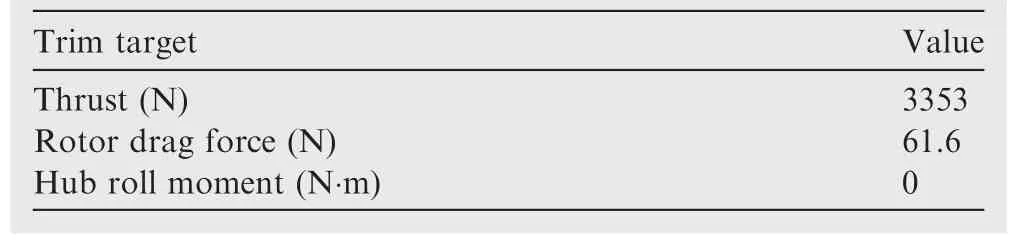
Table 1 Comparison of trim targets of HART II ATR in a high-speed forward flight(μ=0.35).
In the following sub-sections,the proposed optimization framework is verified using Case SH as a reference to the parameter sweep.Then the vibration and performance aspects of the HART II ATR in high-speed forward flights are examined with the actuation schedules depicted in Fig.1.
3.1.Parameter study for validation of optimum result
A parametric sweep study with a single harmonic input(Case SH)according to the actuation frequencies,amplitudes,and phase angles is carried out to examine the vibration and performance characteristic of the HART II ATR and to validate the optimization results.To this end,the amplitudes of the twist moment couple are varied from 1 to 4 N·m with an increase of 1 N·m(ΔT=1 N·m)while the phase angle is changed from 0°to 360°by varying 60°(Δφ =60°)for the respective actuation frequencies of 2/rev to 5/rev.Note that a coarse resolution is adopted in the parameter sweep to avoid heavy computational burden encompassing the whole design space.Only a high-speed forward flight condition is considered in this study.
Fig.5 shows the percentage changes in the total power required at 2/rev actuation with varying amplitudes and phase angles of SH input signals,obtained with reference to the baseline uncontrolled rotor.It is indicated that the active twist introduces substantial variation(up to 5%in peak-to-peak)in the power required to demonstrate the potential of the ATR in practical applications.The condition of the best power required is denoted as a diamond in Fig.5 and is obtained at an amplitude of 3 N·m and a 240°phase angle.The reduction is about 0.76%as compared to that of the baseline uncontrolled rotor.The percentage variations in the VI with respect to that of the baseline rotor are presented in Fig.6.Based on the frequency sweep,the most effective actuation frequency in reducing vibration is seen to be 3/rev,and the other frequency results are not presented explicitly.As is indicated in Fig.6,the minimum vibration is achieved at 3/rev with a 2 N·m amplitude and a 120°phase angle.The reduction gain is about 51%based from the uncontrolled case.
The parameter sweep results presented above are used as a reference for the verification of the present optimization framework.Case SH is again considered for comparison purpose.In the optimization,the design space is discretised using a finer resolution:ΔT=0.1 N·m and Δφ =1°when compared with the sweep study case.Table 2 shows the comparison between the parameter sweep results and the optimum solutions by the PSGA obtained respectively for the power required.Despite the difference in search methods,the agreement between their predicted results is generally good.The deviations in both actuation conditions are mainly due to the usage of much finer resolutions in the optimization than in the parameter sweep study.It is observed that the PSGA optimum leads to an about 16%larger reduction in the power required than that of the parameter sweep.Table 3 presents the comparison of the minimum vibration obtained between the two methods.Again,a reasonable correlation is obtained for the control parameters predicted for the minimum vibration.Itis indicated that the optimum algorithm results in improved gains due to using finer search space intervals for the design variables and,more importantly,employing a modern evolutionary algorithm to systematically search for the design space in the global manner.Based on the comparison study,it is concluded that the present optimization is reliable and suitable to find the best ATR control inputs at given flight conditions.
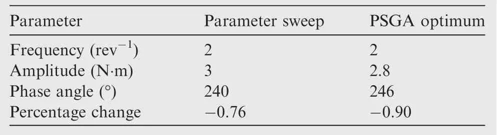
Table 2 Comparison of results between parameter sweep and PSGA optimum for a minimum power required.
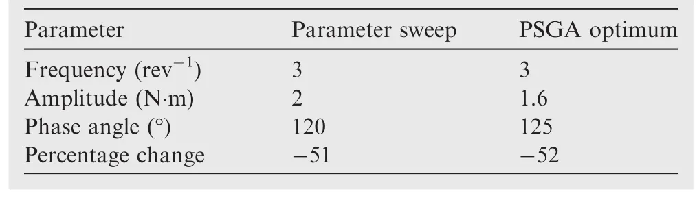
Table 3 Comparison of results between parameter sweep and PSGA optimum for a minimum vibration.
3.2.Influence of rotor wake models
In hover,transition,and low-speed descending flights,the vortex wakes generated from the preceding blades remain close to the rotor disk and may invoke unsteady fluctuations leading to significant changes in rotor-induced velocities as well as the wake geometry.In this situation,a free vortex wake model that can describe the wake distortion in space and time due to the blade motion is desired to calculate accurate blade loadings.It requires computation of the vorticity transport equations for each blade until both wake geometries and induced velocity fields reach a convergence.21This process involves a number ofiterations which are costly in terms of computation.In high-speed forward flights,however,the tip vortices convect aft and below the rotor plane rather quickly,and thus the wake geometry is less distorted and a rigid wake geometry assumption will be valid without a significant error which makes the analysis simple and computationally more effective.22In addition,high-speed flights may induce negative loadings near the blade tip in the advancing side of the rotor resulting in a counter-rotating vortex system.23Therefore,a dual peak wake model is needed to take into account the effect correctly.Fig.7 compares the trim control angles as well as the section airloadsMa2Cn(Mais the Mach number andCnthe section normal force coefficient)of the baseline HART II ATR predicted using the prescribed(rigid)wake model and a rolled-up free wake model.For both wake representations,the dual peak model is adopted.A square root growth with an initial core radius of 0.2c(cis the chord length)is assumed for the wake evolution.As expected,no significant deviation is observed between the two wake models.Based on the observations,only the prescribed wake model is used in this study for computational efficiency.
It should be mentioned that the authors have been involved in the validation study of the HART II rotor for the last decade,particularly in low-speed descending flights.24–26Considering the low-speed flights of the HART II rotor where a close vortex encounter is expected,a rolled-up free vortex wake model has been employed for the computation of airloads.Reasonable correlations are reached with comprehensive dynamics analysis.The details of validation results for various cases(including the baseline case18)of the HART II rotor in descents can be found in the works of Jung and his associates24–26,which are not repeated for compactness.Since CSD predictions using the unsteady aerodynamics analysis with the rolled-up wake model have been verified from the extensive validation study of the HART II rotor in descents,the same free wake model is employed as a reference to cross check the accuracy of the predicted results with the prescribed wake model for the rotor in high-speed conditions.
3.3.Optimum vibration/performance study
The simulation results for the optimal actuation of the rotor in high-speed forward flights are discussed.Fig.8 shows the percentage change in the power required along with the overall vibration VI obtained for the actuation cases with reference to the baseline uncontrolled rotor when the objective function is engaged only to maximize the rotor performance(i.e.,β2=0 in Eq.(3)).As is seen,either non-harmonic twist schedule(Cases NHa and NHb)indicates superior performance than their harmonic counterpart Case SH.The best performance gain is reached with Case NHa,which exhibits a 1.5%reduction in the total power required,whereas a 0.9%reduction is obtained with Case SH.Given that the objective function is engaged only with the performance optimization,however,the VI becomes increased for all the actuation cases.The largest increment is found also with the same Case NHa,which illustrates the inherent complexity of the problem.
Fig.9 shows the resulting actuation deployment scenarios for the cases considered.Case NHa that shows the most remarkable gains(Fig.8)is represented as the solid continuous line while the other cases are denoted as the dotted line(Case SH)and the dashed-dot line(Case NHb),respectively.It is seen that the deployment schedules differ substantially between the cases,except near the front and rear zones of the rotor disk.This is somewhat different from the lowspeed descending flight conditions13where a close similarity between the actuation schedules is clearly attained.It is probable that the high-speed forward flight conditions contain multiple optima for the minimum power resulting in significant variations in the twist deployment schedules.The deviations in actuation profiles affect the vibration characteristic in a large scale,as observed in Fig.8.The twist actuations actually bring changes in pitch angles via elastic twist deformation.Fig.10 presents the total(elastic plus rigid)pitch angles at the blade tip as well as the net elastic twist angles obtained for the cases considered in Fig.8.Note that the baseline uncontrolled results are also inserted in the plot for a reference purpose.As is seen in Fig.10(a),all the cases produce nearly identical waveforms for the total pitch angle by the retrimming process.However,the corresponding elastic twist deformations according to the twist scenarios appear quite dissimilar as expected from the actuation profiles depicted in Fig.9.Among the cases,the best optimum performance profile NHa indicates more deviations compared to the other two.A predominant elastic pitch-down motion in most of the advancing region along with prevailed pitch-up in the retreating region is observed in Case NHa.It should be mentioned that,other than the harmonic actuation,the non-harmonic schedules represent significant offset moments leading to biased elastic twist responses as seen in Fig.10.However,this biased response is countered by cyclic pitch control inputs in the course of re-trimming the rotor.
The mechanism of a reduction in power required is explained considering the distribution of section airloads over the rotor disk.Fig.11 shows the section normal forceMa2Cnobtained for the baseline and Case NHa,denoted in a contour format.It is indicated that the section airloads become redistributed after the application of the ATR input.It should be mentioned that the negative loading zones present around the azimuth angle of 90°at the blade tip for the baseline case are shifted more toward the second quadrant with decreased strengths by the actuation NHa.To aid this observation,the Angles of Attack(AOA)as well as ΔAOA distributions obtained for the two Cases are presented in Figs.12 and 13,respectively.The ΔAOA is obtained by subtracting the AOA of the baseline case from that of case NHa.It is observed that,by the ATR input for Case NHa,the AOA’s particularly in the inboard region around 90°azimuth angles are increased slightly.This increase is accompanied by a decrease of the AOA in the retreating side,which is balanced out by the trim process.The increase in the AOA induced by the twist actuation around the azimuth angle of 90°appears to be responsible for alleviating the negative loadings and improving the performance for Case NHa.
Fig.14 shows the percentage change in the power required and the overall vibration of the three ATR schedules when the objective function is engaged with the vibration only.In this situation,the weight factor β2in Eq.(3)is activated while β1is nullified.As is expected,the vibration levels for all the cases are decreased significantly while the power required increases somewhat.Among the twist scenarios,Case NHb exhibits the best vibration reduction amounting about 61%and Case NHa shows the least vibration reduction gain.In Fig.15,the twist deployment schedules with respect to the cases are presented for comparison purpose.Despite the differences in the waveforms of the cases,there exist some similarities along the rotor azimuth.Particularly,the best vibration reduction Case NHb produces a positive(pitch-up)twist moment in parts of the advancing side and a negative twist moment in the third quadrant of the rotor disk which are essentially in phase with those of the harmonic actuation Case SH.In general,Case NHa misses this pattern except near either 90°or 270°azimuth angle zones where the actuation input is in phase with that of Case SH.The similarity in waveform patterns between Cases NHa and SH attributes to a larger vibration reduction than that in Case NHb.One thing to point out is that,when comparing the twist schedules between Figs.9 and 15,the pitch-down input in portions of the advancing side generated possibly to counter the negative loading in the performance optimization(Case NHa)gets almost reversed(i.e.,pitch-up)for Case NHb at the vibration optimum input.This again illustrates the complexity and significance of introducing proper deployment scenarios in active rotor applications.
A simultaneous reduction in both the power required and the overall vibration is attempted next.To this purpose,the weighting factors in Eq.(3)are activated at once.Since the performance and vibration measures are fundamentally different from each other,an appropriate scaling law is required to make their contributions comparable and meaningful.In this study,each weight factor βiis varied accordingly to match the relative magnitudes(power required vs vibration)nearly identical.Fig.16 presents the percentage changes in the power required and hub vibration with respect to the baseline values.It is seen that,with the multi-objective optimization,both the total power required and the overall vibration become decreased significantly.Among the actuation cases,Case NHb shows a good potential in reducing vibration and enhancing performance in a simultaneous manner.The vibration index is reduced by 49%while the power required is decreased by 0.6%.Note that the vibration level in Case NHa is increased slightly(within 1%)compared to the baseline values.This increase may be countered by adjusting the weight factors;however,no attempt is made considering the level of increase is virtually negligible.It should be mentioned that the weight factors in the multi-objective optimization can be varied appropriately to produce the best outcomes for vibration and/or performance.The corresponding ATR schedules for each of the actuation cases are compared in Fig.17.The relative waveforms appear in phase with each other as can be seen in the plot.
3.4.CFD/CSD coupled results
A CFD/CSD coupled analysis which allows a physics-based simulation is indeed necessary for improved predictions on the vibration and performance of a rotorcraft.Since this re fined approach inevitably comes at the cost of a heavy computational burden,it gets easily impractical when the rotorcraft aeromechanics analysis is combined with an optimization algorithm where a number ofiterative computations are required.To circumvent the computational issue and figure out the detailed physics behind the performance gains due to the twist actuation,the optimized schedules reached using the CSD approach are simply adopted for more re fined analysis by a loose CFD/CSD coupling.A structured,compressible Navier–Stokes solver KFLOW is used for the CFD code.27The same loose coupling algorithm adopted by Jung et al.28,29and known as delta airloads technique is employed to couple the CAMRAD II and KFLOW codes.In this method,the information between the blade motion results from the CSD code and the airloads from the CFD analysis is exchanged to the other code per revolution basis.The coupling iteration is marched until the airloads,blade motions,and control angles do not vary significantly between the coupling iterations.The coupling generally requires 6 to 7 iteration cycles before the final convergence is reached.Interested readers may find more details of the loose coupling algorithm from Refs.28,29
A moving overlapped Chimera grid system with two different types of grids(blade grid and background grid)is employed to describe the flow field around the rotor.An isolated rotor condition is assumed and the effects of the fuselage and the hub are neglected.Fig.18 shows a perspective view of the grid system for the whole computational domain for the HART II ATR rotor.The C-mesh topology is used to create the blade grids.The blade grids extend 1.5 times of the chord length away from the blade surface in all directions.The body grids are clustered near the leading edge,trailing edge,and blade tip regions.They are clustered along the normal direction near the wall.The background grids consist of an inner region that extends 4 chord lengths above,3 chord lengths below from the blade,and 1.5 chord lengths away from the blade tip.The inner region has a uniform spacing in all directions.The far field boundary is located 5 times larger than the blade radius from the rotor hub.The number of grids used is 3.7 million for the blade grids and 12.5 million for the background grids,respectively,resulting in 16.2 million grids overall for the rotor.
For the coupled CFD/CSD analysis,the authors’previous works28,29are used and modified to incorporate ATR applications implemented along the blade span and azimuth domain of the rotor disk.Considering the high-speed forward flight condition(where the blade-vortex interaction is of less interest),an isolated rotor system with a 0.15coff-body grid spacing is adopted for the aeromechanics computation.In addition,the first-order Roe scheme along with a 0.2°time step size is employed for the time-accurate solution of the rotor.Fig.19 presents the iteration history of the trim control angles(Fig.19(a))and the section airloadsMa2Cn(Fig.19(b))with coupling cycles.It is indicated that all the predicted values(i.e.,trim parameters,airloads,and blade motions)become converged after about six cycles of coupling iterations are marched.Fig.20 illustrates the section normal forcesMa2Cnin a contour form predicted using the CSD and CFD/CSD approaches,respectively,for the baseline uncontrolled rotor.Both predictions indicate similar patterns in the distribution of section airloads over the rotor disk except stronger peaks in the CFD/CSD predictions with slight shifts in phases.This pattern is repeated in Fig.21 where the section airloadsMa2Cnat 87%radial stations are plotted with respect to the azimuthal domain.While the peak-to-peak amplitudes of the CFD/CSD predictions are greater than those of CSD,a phase shift amounting about 20°is observed around the 90°azimuth angle.This kind of phase shifts has been encountered in validation studies of the UH-60A airloads program particularly when dealing with high-speed forward flights.30It should be mentioned that the CSD predictions capture the general trends of the aerodynamic loadings of the rotor,even though the negative loadings apparent in the advancing side are underpredicted significantly.
Fig.22 presents the percentage changes in the power required with the variation of phase angles estimated using the CSD and CFD/CSD coupled analyses,respectively,for the actuation Case SH.A 2/rev with an amplitude of 3 N·m is employed for the twist control.The CSD results are identical with those referred in Table 2 for the parameter sweep study.To verify CSD optimum results and investigate solution trends,CFD/CSD coupling is carried out using nearby parameter conditions(180°and 300°)at the best optimum condition of Case SH having a phase angle of 240°.Despite substantial deviations in the relative gains in the power required,both waveforms obtained near the optimum conditions are found to be similar between the CSD and CFD/CSD predictions.It is observed that a more than 4.6%reduction is reached with the CFD/CSD analysis as compared with only a 0.76%gain by the CSD approach.These results confirm that the optimization study performed using the CSD approach is reasonable to produce the best actuation condition but less satisfactory in the actuation gains(magnitudes).As presented in Fig.21,much weaker negative loadings predicted using the CSD code are possible sources of smaller gains in the power required than the CFD/CSD coupled results.Actually,the power required is associated more with the rotor drag force since most of the gains are due to the decrease in the profile power.Fig.23 presents the effect of the twist actuation with Case SH on section drag forcesMa2Cxpredicted using either CSD or CFD/CSD approach.It is observed that the section drag forces over the rotor disk are modified significantly due to the twist control.To indicate the differences more clearly,the delta drag forces(ΔMa2Cx)between the baseline uncontrolled case and Case SH are presented for CFD/CSD and CSD,respectively,in Fig.24.It is observed that both approaches indicate strong negative zones(i.e.,reductions)in delta drag forces particularly around the tip region in the fourth quadrant of the rotor disk.The peak values are larger with the CFD/CSD predictions than the CSD results.More pronounced negative zones in delta drag forces of the CFD/CSD predictions contribute to the larger power reduction than that of CSD as observed in Fig.22.It is remarked that the dominant region of increases in delta drag forces in the third quadrant is positioned more inboard than the negative zone in the fourth quadrant and thus affects less for the power required due to the decreased arm length.
The twist actuation inevitably alters the aerodynamic and structural loads(e.g.,pitch link loads)of the rotor through varying the twist amplitudes.The in fluence of the active twist input on structural torsion moments near the blade root(at 14%radial station)is examined for Case SH with respect to the baseline uncontrolled case in Fig.25.A pitch bearing stiffness of 1000 N·m/rad,which is equivalent to a pitch link stiffness of approximately 0.252 million N/m,is used to match the first torsion frequency of the blade and to represent the control system stiffness of the HART II rotor.It is noted that the pitch link loads cannot be obtained since the detailed information on the control system is not available for the HART II rotor.The torsion moment at the root is evaluated instead.It is observed that the peak-to-peak magnitudes of the predicted torsion moments become reduced notably with the application of the twist actuation,mainly due to the reduction in the second quadrant of the rotor disk.Fig.26 illustrates the in fluence of the twist actuation on the wake structure around the rotor,depicted using the Q-criterion colored by the vorticity magnitude.As is expected,the actuation input is seen to affect the flow pattern substantially.These varied geometry and strength in the wake with the twist actuation will in fluence the induced in flow characteristic of the rotor,leading to changes in the vibration and power required as observed in the previous sections.
4.Conclusions
In this work,the best ATR scenarios of a rotor in high-speed conditions are sought using an optimization framework constructed based on a modern evolutionary algorithm PSGA combined with CSD code CAMRAD II.The HART II rotor with surface-mounted MFC actuators is used as a baseline rotor.Three different ATR schedules including two-and four-phased non-harmonic waveforms are introduced to maximize the actuation performance.A CFD/CSD coupling is conducted to supplement the observations made behind the optimum results.Key conclusions are drawn from the study.
(1)The parameter sweep study demonstrates a reasonable validation on optimum results for minimum power required and vibration reduction.More improved gains up to 16%are obtained from the optimization due to the use offiner resolutions than the parameter sweep.
(2)The two-phase non-harmonic actuation Case NHa exhibits the best reduction in the power required when only the performance optimum is engaged.An about 1.5%reduction in the total power required is reached with respect to the baseline uncontrolled rotor.More pronounced elastic pitch-down in the advancing side and pitch-up in the retreating side are observed with Case NHa than those with the other cases.The elastic pitch motions induced due to the twist input appear to be responsible for the improved gains without affecting much on the total pitch angles.
(3)The larger reduction in the power required for Case NHa is explained comparing the section normal forces with the control inputs.The negative loading zones present around the azimuth angle of 90°near the blade tip become shifted toward the second quadrant of the rotor with decreased strengths.The increases in AOA in the inboard region at the azimuth angle of 90°contribute to alleviate the negative loadings and to reduce the power required after all.
(4)The best vibration reduction gains are achieved with the four-phased non-uniform actuation case NHb when the optimization is engaged only with the vibration reduction.An about 61%decrease in the hub vibration is obtained with the actuation as compared with the baseline case.
(5)The CFD/CSD coupling results in similar trends in power reduction with much larger gains in comparison with CSD predictions.The percentage reductions are 4.6%and 0.76%for the CFD/CSD and CSD analyses,respectively.The distributions of delta drag forces obtained between the predictions with and without the twist control are plotted to identify the source of reduction gains.The pronounced zone with negative delta drag forces near the blade tip in the fourth quadrant is shown to play a dominant role in improved performance.
Acknowledgements
This research was supported by Basic Science Research Program through the National Research Foundation of Korea(NRF)funded by the Ministry ofEducation (No.2017R1D1A1A09000590).This paper resulted from the Konkuk University research support program.The authors thank the HART II test team for the data and Manoj K.Dhadwal for his help in using the PSGA code.
1.Leishman JG.Principles of helicopter aerodynamics..Cambridge:Cambridge University Press;2000.p.55–8.
2.Chen P,Chopra I.Induced strain actuation of composite beams and rotor blades with embedded piezoceramic elements.Smart Mater Struct1996;5:35–48.
3.Chopra I.Status of application of smart structures technology to rotorcraft systems piezoceramic elements.J Am Helicopter Soc2000;45(4):228–52.
4.Thakkar D,Ganguli R.Dynamic response of rotating beams with piezoceramic actuation.J Sound Vib2004;270(4):729–53.
5.Thakkar D,Ganguli R.Helicopter vibration reduction in forward flight with induced-shear based piezoceramic actuation.Smart Mater Struct2004;13(3):599–608.
6.Pawar PM,Jung SN.Active twist control methodology for vibration reduction of a helicopter with dissimilar rotor system.Smart Mater Struct2009;18(3):1–11.
7.Wilbur ML,Yeager WT,Sekula MK.Further examination of the vibratory loads reduction results from the NASA/Army/MIT active twist rotor tests.Proceedings of the American Helicopter Society 58th annual forum;2002 June 11–13;Montreal.Fairfax 790(VA):American Helicopter Society;2002.
8.Fogarty DE,Wilbur ML,Sekula MK.A computational study of BVI noise reduction using active twist control.Proceedings of the American Helicopter Society 66th annual forum;2010 May 11–13;Phoenix(AZ).Fairfax(VA):American Helicopter Society;2010.
9.Yeo H.Assessment of active control for rotor performance enhancement.J Am Helicopter Soc2008;53(2):152–63.
10.Lim JW,Boyd Jr DD,Hoffmann F,van der Wall BG,Kim DH,Jung SN,et al.Aeromechanical evaluation of smart-twisting active rotor.Proceedings of the 40th European rotorcraft forum;2014 Sep 2–5;Southampton.London:Royal Aeronautical Society;2014.
11.Fogarty DE,WilburML,SekulaMK.The effect of non-harmonic active twist actuation on BVI noise.Proceedings of the American Helicopter Society 67th annual forum proceedings;2011 May 3–5;Virginia Beach(VA).Fairfax(VA):American Helicopter Society;2011.
12.Jain R,Yeo H,Chopra I.Computational fluid dynamics-computational structure dynamics analysis of active control of helicopter rotor for performance improvement.J Am Helicopter Soc2010;55(4):1–14.
13.You YH,Dhadwal MK,Jung SN.Optimal active twist input scenario for rotor performance improvement and vibration reduction.Proceedings of the 41th European rotorcraft forum;2015 Sep 1–4;Munich.London:Royal Aeronautical Society;2015.
14.Dhadwal MK,Jung SN,Kim CJ.Advanced particle swarm assisted genetic algorithm for constrained optimization problems.Comput Optim Appl2014;58(3):781–806.
15.Johnson W.CAMRAD II,Comprehensive analytical model of rotorcraft aerodynamics and dynamics.Palo Alto(CA):Johnson Aeronautics;1992.
16.You YH,Jung SN.Optimal active twist control scenario for performance and vibration perspective of a helicopter rotor.Proeedings of the American Helicopter Society international technical meeting on aeromechanics design for vertical lift;2016 Jan 20–22;San Francisco(CA).Fairfax(VA):American Helicopter Society;2016.
17.US Army Aviation And Missile Command.Requirements for rotorcraft vibration specifications,modeling and testing,aeronauti-cal design standard,standard practice:ADS-27A-SP.Redstone Arsenal(AL):US Army Aviation And Missile Command;2006.
18.van der Wall BG.2nd HHC aeroacoustic rotor test(HART II)–Part I:Test documentation.Braunschweig:German Aerospace Center(DLR);2003.Report No.:Institute Report IB 111–2003/31.
19.Yeo H,Romander EA,Norman TR.Investigation of rotor performance and loads of a UH-60A individual blade control system.J Am Helicopter Soc2011;56(4):1–18.
20.Johnson W.Helicopter theory.New York:Dover Publications;1994.p.219.
21.Roget B.Simulation of active twist and active flap control on a model-scale helicopter rotor.Proceedings of the 24th AIAA applied aerodynamics conference;2006 June 5–8;San Francisco(CA).Reston:AIAA;2006.
22.Johnson W.Rotorcraft aeromechanics.Cambridge:Cambridge University Press;2013.p.366–413.
23.Yeo H.Investigation of UH-60A rotor performance and loads at high advance ratios.J Aircraft2013;50(2):576–89.
24.Park JS,Jung SN,You YH,Park SH,Yu YH.Validation of comprehensive dynamics analysis results for a rotor in descending flight.Aircr Eng Aerosp Tec2011;83(2):75–84.
25.Jung SN,You YH,Dhadwal KM,Riemenschneider J,Hagerty B.Study on blade property measurement and its influence on air/structural loads.AIAA J2015;53(11):3221–32.
26.van der Wall BG,Lim JW,Smith MJ,Jung SN,Bailly J,Baeder JD,et al.The HART II international workshop:An assessment of the state-of-the-art in comprehensive code prediction.CEAS Aeronaut J2013;4(3):223–52.
27.Kim JW,Park SH,Yu Y.Euler and Navier-Stokes simulations of helicopter rotor blade in forward flight using an overlapped grid solver.Proceedings of the 19th AIAA CFD conference;2009 June 22–25;San Antonio(TX).Reston(VA):AIAA;2009.
28.Jung SN,You YH,Kim JW,Sa JH,Park JS,Park SH.Correlation of aeroelastic responses and structural loads for a rotor in descending flight.J Aircraft2012;49(2):398–406.
29.Jung SN,Sa JH,You YH,Park JS,Park SH.Loose fluid-structure coupled approach for a rotor in descent incorporating fuselage effects.J Aircraft2013;50(4):1016–26.
30.Datta A,Sitaraman J,Chopra I,Baeder JD.CFD/CSD prediction of rotor vibratory loads in high-speed flight.J Aircraft2006;43(6):1698–709.
31 May 2016;revised 28 October 2016;accepted 21 January 2017
Available online 7 June 2017
*Corresponding author.
E-mail address:snjung@konkuk.ac.kr(S.N.JUNG).
Peer review under responsibility of Editorial Committee of CJA.
Production and hosting by Elsevier
http://dx.doi.org/10.1016/j.cja.2017.04.017
1000-9361©2017 Chinese Society of Aeronautics and Astronautics.Production and hosting by Elsevier Ltd.
This is an open access article under the CC BY-NC-ND license(http://creativecommons.org/licenses/by-nc-nd/4.0/).
Active twist;
High-speed flight;
Hub vibration;
Non-harmonic;
Power required
杂志排行

CHINESE JOURNAL OF AERONAUTICS的其它文章
- Wake structure and similar behavior of wake profiles downstream of a plunging airfoil
- Self-sustained oscillation for compressible cylindrical cavity flows
- Numerical studies of static aeroelastic effects on grid fin aerodynamic performances
- A new vortex sheet model for simulating aircraft wake vortex evolution
- Linear stability analysis of interactions between mixing layer and boundary layer flows
- Aerodynamic multi-objective integrated optimization based on principal component analysis