Theoretical aspects of selecting repeated unit cell model in micromechanical analysis using displacement-based finite element method
2017-11-20LijunGAOChengyuWANGZhanliLIUZhuoZHUANG
Lijun GAO,Chengyu WANG,Zhanli LIU,Zhuo ZHUANG
Department of Engineering Mechanics,School of Aerospace Engineering,Tsinghua University,Beijing 100084,China
Theoretical aspects of selecting repeated unit cell model in micromechanical analysis using displacement-based finite element method
Lijun GAO,Chengyu WANG,Zhanli LIU,Zhuo ZHUANG*
Department of Engineering Mechanics,School of Aerospace Engineering,Tsinghua University,Beijing 100084,China
Repeated Unit Cell(RUC)is a useful tool in micromechanical analysis of composites using Displacement-based Finite Element(DFE)method,and merely applying Periodic Displacement Boundary Conditions(PDBCs)to RUC is almost a standard practice to conduct such analysis.Two basic questions arising from this practice are whether Periodic Traction Boundary Conditions(PTBCs,also known as traction continuity conditions)are guaranteed and whether the solution is independent of selection of RUCs.This paper presents the theoretical aspects to tackle these questions,which unify the strong form,weak form and DFE method of the micromechanical problem together.Specifically,the solution’s independence of selection of RUCs is dealt with on the strong form side,PTBCs are derived from the weak form as natural boundary conditions,and the validity of merely applying PDBCs in micromechanical Finite Element(FE)analysis is proved by referring to its intrinsic connection to the strong form and weak form.Key points in the theoretical aspects are demonstrated by illustrative examples,and the merits of setting micromechanical FE analysis under the background of a clear theoretical framework are highlighted in the efficient selection of RUCs for UniDirectional(UD)fiber-reinforced composites.
©2017 Chinese Society of Aeronautics and Astronautics.Production and hosting by Elsevier Ltd.This is an open access article under the CC BY-NC-NDlicense(http://creativecommons.org/licenses/by-nc-nd/4.0/).
1.Introd uction
Micromechanical approach has served as a successful tool in the characterization and analysis of composite materials which are widely used in aeronautics,energy and mechanical engineering due to their superior behavior compared with homogeneous materials.The mission of micromechanical analysis of composites generally falls into two types:to obtain the effective mechanical(or thermal)properties of composites from the material properties and phase distribution of their constituents and to evaluate the microscopic stress(or temperature)field.Both analytical and numerical methods have been developed to accomplish the mission.
Analytical methods to estimate the effective properties of composites,based on various assumptions and simplifications,include the self-consistent method,1Mori-Tanaka method2,3and differential scheme,4to cite just a few of them.In addition to the direct estimation,the variational principle5is employed to derive the upper and lower bounds,which reasonable effective mechanical properties should fall into.However,analytical methods generally ignore the detailed phase distribution of constituents and thus give only rough estimation of macroscopic properties.Besides,microscopic stress distribution in the heterogeneous scale during the deformation process,which is needed to evaluate the plastic yield,6,7fracture8and damage initiation behavior9of composites,cannot be obtained through analytical methods.Despite the limitations mentioned above,analytical methods provide some theoretical insights into the evaluation of effective properties and serve to be a comparative reference to numerical methods.
Displacement-based Finite Element(DFE)method,on which many commercial numerical codes are based,is the dominant tool among various numerical methods for micromechanical analysis,which also include fast Fourier transform,10meshfree method11and so on.Only DFE method is concerned in this work,so the Finite Element Method(FEM)hereinafter will implicitly represent its displacementbased type.Micromechanical FE analysis,using the concepts of Representative Volume Element(RVE)12,13or Repeated Unit Cell(RUC),14,15can be carried out to evaluate the heterogeneous stress field of composites,thus more accurately predicting the effective properties and characterizing microscopic yield and damage behavior compared to analytical methods.Micromechanical FE analysis is also useful in determining the accuracy and applicability of analytical methods.12
RVE is generally considered to be a subvolume of composites with a large enough scale compared with the heterogeneity and an effective representative of real composites in the aspects of both macroscopic properties and microscopic behavior.In RVE,inclusions can be arranged randomly in matrix just as in real composites,but periodic microstructure must be guaranteed to make Periodic Boundary Conditions(PBCs)applicable in FE analysis.9,12,13In comparison with RVE,RUC is usually defined as the translational repeated unit cell while inclusions are positioned in a periodic array microscopically for the purpose of simplifying the problem.However,the concepts of RVE and RUC are not distinguished sometimes in the literature.16,17RVE with periodic microstructure,which is a must for micromechanical FE analysis,can at least be treated as a special case of RUC with translational symmetry and thus RUC will be used in the following sections.
For a particular periodic microstructure of composites,it is always possible to select RUCs of different geometric shapes or at least several neighboring smallest RUCs as a bigger RUC.17–19In most papers,10,17,18it is concluded immediately that micromechanical FE analysis with different RUCs for the same composite will produce the same result,which is admitted by the authors of this paper to be seemingly quite intuitive but a lack of necessary theoretical rigor and it will be indicated later in this work that the conclusion is not that straightforward actually.To the best of the authors’knowledge,a paper20devoted to diversified numerical demonstration of this conclusion is the only account of this problem available in the literature,which has been attracting considerable attention since its publication(Citation increased by 15 in the year 2015)and serves as a clear indicator that a good few do not take the conclusion as granted but feel a need of supporting evidence.The numerical demonstration,while helpful and persuasive in some sense,still does not reveal the theoretical nature of the problem.Furthermore,despite the apparent obviousness of the conclusion,inefficient choice of RUCs,most frequently encountered in micromechanical FE analysis of UniDirectional(UD)fiber-reinforced composites,appears from time to time,which may result from a lack of knowledge on the theoretical background of selecting RUCs.Specifically,various FE models of UD fiber-reinforced composites,such as two-dimensional plain strain or plain stress models,7and three-dimensional FE models consisting of single layer21,22or multiple layers23–26of elements,exist in the literature.Besides,great efforts were exerted to develop a special generalized strain element27,28to model the deformation of UD fiberreinforced composites.However,such efforts should be avoided considering that micromechanical FE analysis of UD fiber-reinforced composites maintains theoretical consistency with that of other composites.Except an efficient choice of RUC,other geometric symmetry except the translational symmetry,such as reflectional symmetry and rotational symmetry,29,30can also be exploited to obtain an efficient unit cell,but it is not the emphasis of this paper and will not be dealt with further.
This paper aims to present a theoretical framework with respect to selection of RUCs in the micromechanical FE analysis of composites.Some key points in the framework are examined in illustrative examples and comparison is made with available results in the literature.
2.Two questions about micromechanical FE analysis with different RUCs
PBCs are expressed in Eqs.(1)and(2),16which are Periodic Displacement Boundary Conditions(PDBCs)and Periodic Traction Boundary Conditions(PTBCs),respectively.wherel+andl-identify thelth pair of two parallel boundary faces of RUC,are displacements on the boundary facesl+andl-,respectively,is the component of the average strain tensor,is the coordinate difference in thexjdirection for thelth pair of two parallel boundary faces,andare the component of stress tensor and unit outer normal on the boundary facel+,respectivelyare defined similarly).Taking the two-dimensional RUC in Fig.1 as an example,displacements and tractions on the sides 1-and 2-are related to those on the sides 1+and 2+,respectively,by PBCs(1)and(2)for given average strains.
In most micromechanical FE analysis,the periodic mesh is generated in RUC and merely PDBCs are applied to all boundary faces.One basic question that naturally arises is whether PTBCs will be satisfied although a certain solution can be obtained by the problem definition above with further elimination of rigid body motion.Such doubt has led to deliberate efforts to apply PTBCs to unit cell31or implication that PTBCs should be handled in a similar manner as PDBCs,32though PBCs are mostly properly dealt with in the literature.This issue had not been paid due attention to until the minimum total potential energy principle was used to demonstrate that PTBCs will be automatically fulfilled and do not need special handling in micromechanical FE analysis.33However,such proof limits its validity to linear elastic material behavior only and in this work similar conclusions will be deduced based on the virtual work principle to cover problems involving nonlinear deformation.
RUCs with different geometric shapes are always available for the same composites.Take the periodic microstructure in Fig.2(a)as an example and different RUCs shown in Figs.2(b)–(e)(also indicated in Fig.2(a))are among the numerous possibilities.One question that arises with different choice of RUCs is whether the same result will be obtained for micromechanical FE analysis.
Both questions raised in the last two paragraphs will be addressed by exploring the theoretical framework of micromechanical FE analysis of composites in the following sections.
3.Theoretical aspects of selecting RUCs in micromechanical FE analysis
The most intuitive way to tackle the two questions proposed in the last section is probably to follow the detailed solution procedure of FE global equation system and to carry on numerical tests,as indeed the very methods used in the paper.20However,attempts to follow the details of solving FE global equation system may probably not produce the desirable results and one of such counterexamples is that PTBCs cannot be fulfilled exactly considering that FEM is only a numerical and approximate method and stress equilibrium conditions cannot be satisfied exactly.Furthermore,though useful numerical tests are,they,as all the other incomplete inductive methods do,lack logic rigor and do not reveal the theoretical nature of the problem.Instead,the proposed questions will be answered by first exploring the strong form and weak form of micromechanical problems and then exploiting the underlying link between the two forms and micromechanical FE analysis in this work.
3.1.Strong form and uniqueness of solution
Problems of solid mechanics can be described in two different but equivalent mathematical formulations:strong form and weak form.The former expressed in differential equations and boundary conditions is characterized by clear physical meaning and allows to probe directly into the nature of the problem,while the latter expressed in integral form constitutes the theoretical basis of FEM to obtain an approximate solution.To a large extent,the existence and uniqueness of solution of a given problem are physical questions and are usually dealt with on the strong form side.The solution of a certain problem must be both existent and unique to make it a well-posed one.When it comes to linear elastic material behavior,equilibrium equations combined with appropriate boundary conditions make a problem well-posed.As for appropriate boundary conditions,usually displacements are prescribed over part of the boundary,whereas tractions are prescribed over the remainder.The existence of solution of such problems is often determined by the physical grounds and quite complicated in mathematics while the uniqueness of solution is guaranteed by the Kirchhoff’s theorem.34
Though PBCs may seem different from those above,application of PDBCs and PTBCs together is proved rigorously to guarantee a unique solution to the RUC boundary-value problem provided that the material is linear elastic.35That is to say,the equilibrium Eq.(3)with PBCs(1)and(2)guarantees a unique solution for linear elastic material behavior.As for elastic-plastic materials whose mechanical behavior is loading history dependent,application of PDBCs and PTBCs to RUC does not guarantee a unique solution to the micromechanical problem unless a certain loading path is specified.The uniqueness of solution is a powerful tool for proving independence of solution from RUC selection.
When PDBCs with the same average strains and PTBCs are applied to RUC-ABCDand RUC-FCMNin Fig.2,a unique solution to RUC-ABCDand another unique solution to RUC-FCMNwill be expected for linear elastic material behavior or nonlinear material behavior with the same loading path specified.Translational packing of deformed RUC-ABCDproducesOPQRin Fig.3,which is valid with displacement compatibility and traction continuity between neighboring RUCs provided by PDBCs and PTBCs,respectively.Obviously the strain-free state ofOPQR(2-by-2 translational packing of RUC-ABCD)is actually RUC-FCMN.We assume thatSis an arbitrary point on the boundary FaceDCof RUCABCDandS'is the point on the opposite boundary FaceABwith translational symmetry withS.Some of other image points ofSafter translational packing of RUC-ABCDareI1,I2andI3inOPQR.When Eqs.(1)and(2)are applied toSandS',Eqs.(4)and(5)are obtained.
where Δxj(S'→S)is the coordinate difference betweenSandS'in thexjdirection prior to deformation.Equations(6)–(8)forI1,I2andI3can be obtained similarly.
where Δxj(I3→I1)is the coordinate difference betweenI3andI1in thexjdirection prior to deformation.Similar conclusions can be drawn for point pairs on SidesADandBC.Notice that deformed RUC-FCMNshould satisfy the same boundary conditions as unit cellOPRS(Eqs.(7)and(8)).Due to uniqueness of solution,OPRSmust be the same as the deformed state of RUC-FCMN.It is thus concluded that the solutions obtained from subjecting RUC-ABCDand RUC-FCMNto the same PBCs are identical.Note that RUC-FCMNcan be covered precisely by translational packing of RUC-ABCDin the proof above,which is actually a special case,and a more general case will be dealt with in the following.
The UD fiber-reinforced composite in a hexagonal layout is taken as an example,as shown in Fig.4,and different RUCs,such as RUC-abcdef,RUC-gahfand RUC-hcdein Fig.4(a),can be chosen.It is obvious that RUC-abcdefcannot be precisely covered by any translational packing of RUC-gahfor RUC-hcde.In this case,a 2-by-2 translational packing of deformed RUC-gahfis used to construct a bigger unit cellgbnein Fig.4(b),of which RUC-abcdefis a subset prior to deformation.mandkare arbitrary points on the Sidesefandaf,respectively.m'andm''are image points ofmin the sense of translational packing of RUC-fhde(or RUC-gahf)and similarlyk'is the image point ofk.As in Eq.(7),the relationship between displacements ofmandm'after deformation(with prescribed average strain
As the unit cellsabchandhcndare identical in nature,the following can be obtained:
That is
Add Eq.(11)to Eq.(9)and Eq.(12)is obtained.
Similarly,
In addition,due to translational packing of RUC-gahf,obviously we have
Similar conclusions can be obtained for point pairs on Sidesabandde.So the displacement and traction conditions obtained from translational packing of RUC-gahfon the borders of the Areaabcdefare the same as PBCs of RUC-abcdef.Therefore,the deformation state of the Areaabcdefobtained from translational packing of RUC-gahfmust be the same as that from RUC-abcdefwith PBCs enforced directly due to uniqueness of solution,and independence of solution from RUC selection is proved again.
Similar procedure as above can be taken to prove independence of solution from choice of RUCs when other RUCs than those above are concerned.So the solution of the micromechanical problem of composites is independent of selection of RUCs for linear elastic material behavior and the conclusion is also valid provided that the same loading path is prescribed for different RUCs in case of elastic-plastic material behavior.
3.2.Weak form implies PTBCs as natural boundary conditions
It is pointed out that PDBCs are essential boundary conditions,which need to be satisfied beforehand,while PTBCs are natural boundary conditions based on the minimum total potential energy principle.33In order to extend scope of application of this conclusion to nonlinear material behavior which is frequently encountered in the micromechanical analysis of composites,PTBCs as natural boundary conditions will be deduced from the virtual work principle and PDBCs here.The virtual work principle is expressed as
where δui,jis the derivative of the virtual displacement δuiwith respect to thejth direction and σijthe component of stress tensor.After applying the Gauss theorem,Eq.(17)becomes
wherenjis the unit outward normal to∂Ω.Due to arbitrariness of the virtual displacement δuiin Ω,the second term on the left-hand side of Eq.(18)has to vanish,which results in the equilibrium equation(the same as Eq.(3))
After substituting Eq.(19)into Eq.(18),Eq.(18)is reduced t o Note thatuiis constrained to satisfy PDBCs on ∂Ω,so its variation δuiis not absolutely arbitrary.To take the variation of Eq.(1),the following Eq.(21)can be obtained:
where x-and x+are the coordinates of two corresponding points whose displacements are constrained by PDBCs.The variation of the right-hand side of Eq.(1)vanishes because bothare given constants.The unit outward normal is opposite in direction for two parallel sides,that is
Take RUC in Fig.1 as an example in a further step,substitute Eqs.(22)and(24)into Eq.(20),and the following equation can be obtained:
where Δx is the translational vector and can be obtained from the geometric structure of a particular RUC.Since δui(x-)is arbitrary,it can be concluded from Eq.(25)that the following equation holds:
Equation(27)or Eq.(28)is actually equivalent to the PTBCs in Eq.(2).So PTBCs as well as the equilibrium equation is implied by the virtual work principle combined with PDBCs,which indicates equivalence between the strong form(equilibrium equation,PDBCs and PTBCs)and weak form(the virtual work principle and PDBCs)of the micromechanical problem.Note that the derivation above does not put any constraint on the material constitutive behavior,so the conclusion is applicable to both linear and nonlinear deformation of composites.
3.3.Micromechanical FE analysis of composites
DFE codes are based on the virtual work principle and the definition of a certain problem in the codes maintains consistency in all aspects with the weak form of the problem.So for the micromechanical FE analysis of composites,merely applying PDBCs is both necessary and sufficient.PTBCs,as natural boundaryconditions,will be satisfied accurately enough as long as a fine enough mesh is adopted.The relationship between the strong form, weak form and FE analysis of RUC micromechanical problems is illustrated in Fig.5.The strong form and weak form,though different in mathematical formulations and handling of boundary conditions,are equivalent to each other,and the DFE method,based on the latter and inheriting the manner of handling boundary conditions from it,provides an effective numerical tool to obtain an approximate solution.
The relationship presented in Fig.5 is of significance in that the very solution can be obtained from DFE method provided that uniqueness of solution is ensured by the strong form of the problem.Recalling that with uniqueness of solution it is independent of choice of RUCs in Section 3.1 and that traction continuity conditions are guaranteed by the weak form in Section 3.2,we can conclude immediately from Fig.5 that using micromechanical FE analysis the converged numerical solution is independent of choice of RUCs and traction continuity conditions are ensured automatically. The validity of merely applying PDBCs in micromechanical FE analysis becomes quite explicit when referring to Fig. 5 for the intrinsic links between the three.
However,caution should be taken when non-uniqueness of solution occurs on the strong form side,because a certain solution depending on the default loading path in DFE codes can be obtained with the possibility of inconformity to the real case.For nonlinear analysis,a default loading path,e.g.the proportional-strain loading in case of prescribed displacement boundary conditions,is usually used in commercial FE codes,and a careful check needs to be done to make sure that the default loading path is wanted.
Micromechanical FE analysis is also frequently used to obtain the effective thermal conductivity and effective permeability of composites or porous materials and independence of solution from selection of RUC in such problems can be proved likewise.In particular for evaluation of effective thermal conductivity,periodic thermal flux conditions can be ensured by merely applying periodic temperature boundary conditions in DFE codes and the solution is independent of selection of RUCs. The theoretical aspects of such problems are quite similar in nature and will not be elaborated in this work except exemplification of thermal conductivity evaluation in the next section.
4.Illustrative examples
4.1.Convergence analysis
The composite in Fig.2 is used in this example.Linear elastic material behavior is assumed for both the matrix and inclusion,and the mechanical properties are listed in Table 1.
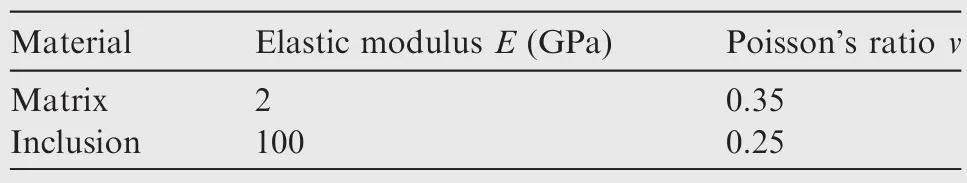
Table 1 Material properties of composite in Fig.2.
The mesh convergence of traction continuity conditions and effective modulus of RUC-ABCDis checked.The average strainis specified and the average stress
whereVis the volume of RUC-ABCD,Sjthe area of the surface normal toxjdirection andPijthe resultant traction inxidirection on the surfaceSj.The average stresses and strains are correlated by the effective stiffness matrix C as in Eqs.(30)and(31).
Relative errorseC33(forC33)andeT(for traction continuity conditions)are defined in Eqs.(32)and(33)to quantify the degree of mesh convergence.
RUC-ABCD,RUC-EFGHand RUC-KLMNwith converged mesh are used to evaluate the microscopic stress field when the same average strains as above are enforced.Stress components on the same path in the three RUCs are plotted in Fig.7.The starting points of the paths of different RUCs are denoted by pointsB,QandOin Figs.2(b)–(d),respectively.The path direction is denoted by arrows,and particularly for Fig.2(c),the path isQ-J-I-Q.As shown in Fig.7,stress components are identical for three different RUCs,which supports the conclusion of independence of solution from selection of RUCs.
4.2.Path dependence of solution for elastic-plastic material behavior
When elastic-plastic deformation is concerned,there will be numerous solutions depending on different loading paths in the micromechanical FE analysis with application of PDBCs.One example is given below.
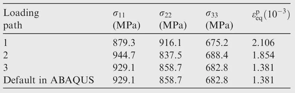
Table 2 Results for four loading paths.
Homogeneous material,which can be seen as the simplest‘composite material” in structure,is used here for simplicity of modeling,saving the effort to check mesh convergence(single-valued strain state).A two-dimensional square RUC is used,as shown in Fig.8(a).The material is assumed to be elastic-plastic with linear hardening law after its initial yielding at 210 MPa.The elastic modulus,Poisson’s ratio and plastic modulus are 70 GPa,0.33 and 7 GPa,respectively.The average strains of the ‘composite” are prescribed asThree loading paths from zero-strain state to the state of given average strains by displacement loading are illustrated in Fig.8(b).With the same PDBCs imposed,four solutions,shown in Table 2,are obtained separately along the default loading path in ABAQUS and the three paths in Fig.8(b).It is indicated that the final stress states and equivalent plastic strains(an indicator of degree of plastic deformation)can vary significantly with different loading paths and that the final stress state resulting from the default loading path is identical to that from Path 3.Further investigation reveals that in solving the FE global equation system with application of PDBCs as displacement constraints,a proportional displacement loading scheme is taken implicitly in ABAQUS,36which interprets the identical final states.Therefore,though a certain solution can be obtained for micromechanical FE analysis of composites with elastic-plastic material behavior when applying PDBCs without loading path control,it means that a default loading path is taken by the solver of DFE codes rather than that the solution is unique.
4.3.Effective mechanical properties of UD fiber-reinforced composites
U D fiber-reinforced composites are usually assumed to be in finitely long in the fiber direction and can be seen as repeated in a period of any finite length.So the length of a RUC in the fiber direction in Fig.9 can be chosen arbitrarily.For a RUC meshed with several layers of elements(Fig.9(b))in the fiber direction,single-layer elements,shown in Fig.9(c),can actually be treated as another meshed RUC while the original RUC can be seen as a larger RUC containing several single-layer-element RUCs.RUC with single-layer elements will be used hereinafter since independence of solution from RUC selection.Therefore,justification for a generalized plane strain condition and development of special generalized plane strain elements27,28for micromechanical FE analysis of UD fiber-reinforced composites are not needed and common three-dimensional solid elements are enough for this task without additional computational cost.
The fiber volume fraction is 47%and the material properties are given in Table 3.In real UD fiber-reinforced composites, fibers are distributed randomly in the transverse cross section and the composites are transversely isotropic macroscopically,which means isotropic mechanical properties in the cross section perpendicular to the fiber direction.Square array and hexagonal array of fibers are usually assumed in micromechanical FE analysis of UD fiber-reinforced composites.In order to make comparison with available results in the literature,square array is assumed in this work.
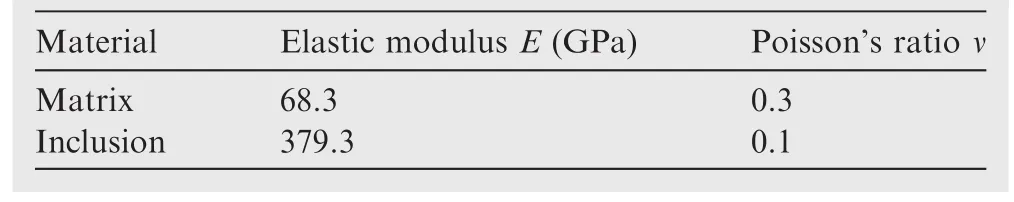
Table 3 Material properties of composite in Fig.9.
A set of simple loading conditions,shown in Fig.10,are applied to the single-layer-element RUC to determine its mechanical properties.The results are shown in Table 4 and comparison is made with results in the literature.The present results generally agree well with those of FEM,analytical methods and experiments.In particular,the present results are almost identical with those of FEM given by Xia et al.,16which is obtained through a multi-layer-element RUC.
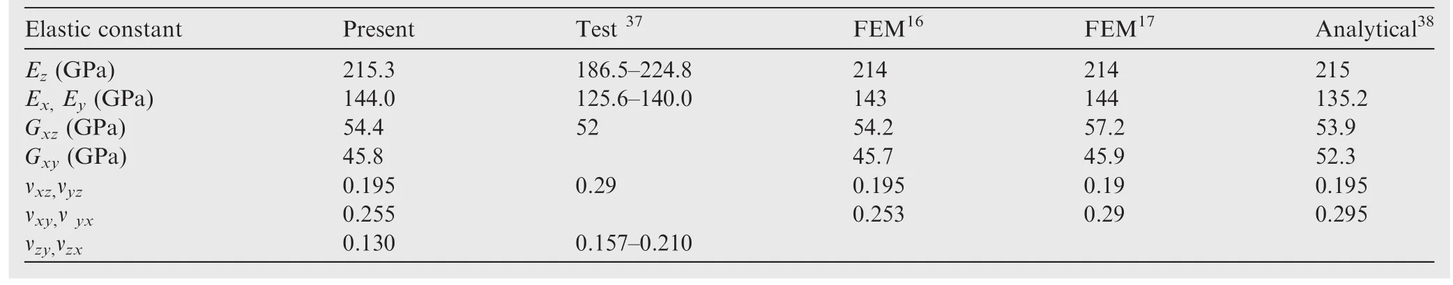
Table 4 Comparison of effective mechanical properties.
Theoretical self-consistency of the present results can be ensured by satisfying Eq.(34)well by all possible combinations ofEand ν.
5.Conclusions
Theoretical aspects with respect to selecting RUCs in the micromechanical FE analysis are presented in this work.Two closely related topics are mainly concerned:traction continuity conditions and uniqueness of solution.A theoretical framework unifying the strong form,weak form and micromechanical FE analysis of composites is established,within which the two topics mentioned above are probed into.Illustrative examples are given to numerically demonstrate the key points in the theoretical framework.The following conclusions can be reached:
(1)The proof of validity of merely applying PDBCs in the micromechanical FE analysis of composites is best conducted in the theoretical framework of the strong form,weak form and DFE method.
(2)In the strong form side of micromechanical problems,application of both PDBCs and PTBCs produces a solution independent of selection of RUCs for linear elastic materials.This is valid for nonlinear material behavior only when a certain loading path is specified.
(3)PTBCs are the natural boundary conditions in the weak form of micromechanical problems,which suggests that only PDBCs need to be imposed in DFE method and that PTBCs will be satisfied automatically upon mesh convergence.This conclusion is applicable to both linear and nonlinear material behavior.
(4)For the micromechanical FE analysis with application of PDBCs only,the solution is independent of choice of RUCs while that for nonlinear material behavior is loading path dependent and caution should be taken to ensure that the loading path is controlled as wished.
The conclusions above can easily be extended to microscopic analysis of composites other than micromechanics(e.g.calculation of effective thermal conductivity and permeability).Finally,it should be noted that the deduction in this work relies on the prerequisite of small deformation,and for large deformation,more independent work should be done to check the applicability.
1.Hill R.A self-consistent mechanics of composite materials.J Mech Phys Solids1965;13(4):213–22.
2.Mori T,Tanaka K.Average stress in matrix and average elastic energy of materials with misfitting inclusions.Acta Metall1973;21(5):571–4.
3.Benveniste Y.A new approach to the application of Mori-Tanaka’s theory in composite materials.Mech Mater1987;6(2):147–57.
4.McLaughlin R.A study of the differential scheme for composite materials.Int J Eng Sci1977;15(4):237–44.
5.Hashin Z,Shtrikman S.A variational approach to the theory of the elastic behaviour of multiphase materials.J Mech Phys Solids1963;11(2):127–40.
6.Carvelli V,Taliercio A.A micromechanical model for the analysis of unidirectional elastoplastic composites subjected to 3D stresses.Mech Res Commun1999;26(5):547–53.
7.Yang QS,Qin QH.Modelling the effective elasto-plastic properties of unidirectional composites reinforced by fibre bundles under transverse tension and shear loading.Mater Sci Eng A2003;344(1–2):140–5.
8.Segurado J,Gonza´lez C,LLorca J.A numerical investigation of the effect of particle clustering on the mechanical properties of composites.Acta Mater2003;51(8):2355–69.
9.Segurado J,LLorca J.Computational micromechanics of composites:The effect of particle spatial distribution.Mech Mater2006;38(8–10):873–83.
10.MichelJC,MoulinecH,SuquetP.Effectivepropertiesofcomposite materialswithperiodicmicrostructure:Acomputationalapproach.Comput Methods Appl Mech Eng1999;172(1–4):109–43.
11.Li LY,Wen PH,Aliabadi MH.Meshfree modeling and homogenization of 3D orthogonal woven composites.Compos Sci Technol2011;71(15):1777–88.
12.Segurado J,Llorca J.A numerical approximation to the elastic properties of sphere-reinforced composites.J Mech Phys Solids2002;50(10):2107–21.
13.Gusev AA.Representative volume element size for elastic composites:A numerical study.J Mech Phys Solids1997;45(9):1449–59.
14.Li S.On the unit cell for micromechanical analysis offibrereinforced composites.Proc R Soc London A Math Phys Eng Sci1983;1999(455):815–38.
15.Li S,Jeanmeure LFC,Pan Q.A composite material characterisation tool:UnitCells.J Eng Math2015;95(1):279–93.
16.Xia Z,Zhang Y,Ellyin F.A unified periodical boundary conditions for representative volume elements of composites and applications.Int J Solids Struct2003;40(8):1907–21.
17.Sun CT,Vaidya RS.Prediction of composite properties from a representative volume element.Compos Sci Technol1996;56(2):171–9.
18.Li S.General unit cells for micromechanical analyses of unidirectional composites.Compos Part A Appl Sci Manuf2001;32(6):815–26.
19.Govaert LE,Peijs T.Micromechanical modeling of time-dependent transverse failure in composite systems.Mech Time-Dependent Mater2000;4(3):275–91.
20.Xia Z,Zhou C,Yong Q,Wang X.On selection of repeated unit cell model and application of unified periodic boundary conditions in micro-mechanical analysis of composites.Int J Solids Struct2006;43(2):266–78.
21.Aghdam MM,Pavier MJ,Smith DJ.Micro-mechanics of off-axis loading of metal matrix composites using finite element analysis.Int J Solids Struct2001;38(22–23):3905–25.
22.Caporale A,Luciano R,Sacco E.Micromechanical analysis of interfacial debonding in unidirectional fiber-reinforced composites.Comput Struct2006;84(31–32):2200–11.
23.Ran Z,Yan Y,Li J,Qi Z,Yang L.Determination of thermal expansion coefficients for unidirectional fiber-reinforced composites.Chinese J Aeronaut2014;27(5):1180–7.
24.Devireddy S, Bhaskara R, Biswas S. Effect of fiber geometry and representative volume element on elastic and thermal properties of unidirectional fiber-reinforced composites.J Compos2014;2014:1–12.
25.Yang L,Wu Z,Cao Y,Yan Y.Micromechanical modelling and simulation of unidirectional fibre-reinforced composite under shear loading.J Reinf Plast Compos2015;34(1):72–83.
26.Jiang WG,Zhong RZ,Qin QH,Tong YG.Homogenized finite element analysis on effective elastoplastic mechanical behaviors of composite with imperfect interfaces.Int J Mol Sci2014;15(12):23389–407.
27.Taliercio A.Macroscopic strength estimates for metal matrix composites embedding a ductile interphase.Int J Solids Struct2007;44(22–23):7213–38.
28.Taliercio A.Generalized plane strain finite element model for the analysis of elastoplastic composites.Int J Solids Struct2005;42(8):2361–79.
29.Li S,Kyaw S,Jones A.Boundary conditions resulting from cylindrical and longitudinal periodicities.ComputStruct2014;133:122–30.
30.Li S,Zou Z.The use of central reflection in the formulation of unit cells for micromechanical FEA.Mech Mater2011;43(12):824–34.
31.Yeh JR.The effect of interface on the transverse properties of composites.Int J Solids Struct1992;29(20):2493–502.
32.Drago A,Pindera MJ.Micro-macromechanical analysis of heterogeneous materials:macroscopically homogeneous vs periodic microstructures.Compos Sci Technol2007;67(6):1243–63.
33.Li S.On the nature of periodic traction boundary conditions in micromechanical FE analyses of unit cells.IMA J Appl Math2012;77(4):441–50.
34.Knops RJ,Payne LE.Uniqueness theorems in linear elasticity,vol.19.New York:Springer Scienceamp;Business Media;1971.p.32–53.
35.Suquet P.Elements of homogenization theory for inelastic solid mechanics.In:Sanchez-Palencia E,Zaoui A,editors.Homogenization techniques for composite media.Berlin:Springer-Verlag;1987.p.194–275.
36.Dassault Syste`mes.ABAQUS analysis user’s guide.Pairs:Dassault Syste`mes;2014.
37.Kenaga D,Doyle JF,Sun CT.The characterization of boron/aluminum composite in the nonlinear range as an orthotropic elastic-plastic material.J Compos Mater1987;21(6):516–31.
38.Hashin Z,Rosen BW.The elastic moduli offiber-reinforced materials.J Appl Mech1964;31(2):223–32.
28 May 2016;revised 13 December 2016;accepted 17 March 2017
Available online 7 June 2017
*Corresponding author.
E-mail address:zhuangz@tsinghua.edu.cn(Z.ZHUANG).
Peer review under responsibility of Editorial Committee of CJA.
Production and hosting by Elsevier
http://dx.doi.org/10.1016/j.cja.2017.05.010
1000-9361©2017 Chinese Society of Aeronautics and Astronautics.Production and hosting by Elsevier Ltd.
This is an open access article under the CC BY-NC-ND license(http://creativecommons.org/licenses/by-nc-nd/4.0/).
Finite element method;
Micromechanics of composites;
Periodic boundary condition;
Repeated unit cell;
Theoretical aspect;
Traction continuity
杂志排行

CHINESE JOURNAL OF AERONAUTICS的其它文章
- Wake structure and similar behavior of wake profiles downstream of a plunging airfoil
- Self-sustained oscillation for compressible cylindrical cavity flows
- Numerical studies of static aeroelastic effects on grid fin aerodynamic performances
- A new vortex sheet model for simulating aircraft wake vortex evolution
- Linear stability analysis of interactions between mixing layer and boundary layer flows
- Aerodynamic multi-objective integrated optimization based on principal component analysis