Coupled Lagrangian impingement spray model for doublet impinging injectors under liquid rocket engine operating conditions
2017-11-20QiangWEIGuozhuLIANG
Qiang WEI,Guozhu LIANG
School of Astronautics,Beihang University,Beijing 100083,China
Coupled Lagrangian impingement spray model for doublet impinging injectors under liquid rocket engine operating conditions
Qiang WEI,Guozhu LIANG*
School of Astronautics,Beihang University,Beijing 100083,China
To predict the effect of the liquid rocket engine combustion chamber conditions on the impingement spray,the conventional uncoupled spray model for impinging injectors is extended by considering the coupling of the jet impingement process and the ambient gas field.The new coupled model consists of the plain-orifice sub-model,the jet-jet impingement sub-model and the droplet collision sub-model.The parameters of the child droplet are determined with the jet-jet impingement sub-model using correlations about the liquid jet parameters and the chamber conditions.The overall model is benchmarked under various impingement angles,jet momentum and offcenter ratios.Agreement with the published experimental data validates the ability of the model to predict the key spray characteristics,such as the mass flux and mixture ratio distributions in quiescent air.Besides,impinging sprays under changing ambient pressure and non-uniform gas flow are investigated to explore the effect of liquid rocket engine chamber conditions.First,a transient impingement spray during engine start-up phase is simulated with prescribed pressure profile.The minimum average droplet diameter is achieved when the orifices work in cavitation state,and is about 30%smaller than the steady single phase state.Second,the effect of non-uniform gas flow produces off-center impingement and the rotated spray fan by 38°.The proposed model suggests more reasonable impingement spray characteristics than the uncoupled one and can be used as the first step in the complex simulation of coupling impingement spray and combustion in liquid rocket engines.
©2017 Chinese Society of Aeronautics and Astronautics.Production and hosting by Elsevier Ltd.This is an open access article under the CC BY-NC-NDlicense(http://creativecommons.org/licenses/by-nc-nd/4.0/).
1.Introduction
Doublet impinging injectors are frequently used in bipropellant hypergolic liquid rocket engines for rapid atomization and mixing in a short distance.The oxidizer and fuel react as soon as the two jets collide and break up into droplets.A stable liquid sheet is formed in the perpendicular direction when two laminar jets impinge on each other.Large droplets shed from the rim of the sheet.1,2Thickness distribution of the sheet and droplet sizes could be calculated with the potential flow method and the instability theory.3But in the regime of liquid rocket engines,turbulent jets break up immediately around the impingement point,and in this case analytical theory on laminar sheets fails to predict the spray characteristics well.Under this circumstance,the research on spray characteristics of doublet impinging injectors,such as mass flux,mixture ratio,and droplet size,was mainly done experimentally.4–6In terms of the chamber combustion efficiency,the mass flux and the mixture ratio distributions play important roles.7A uniform mass flux distribution increases the combustion efficiency as well as the combustion instability.High trust level liquid rocket engines may contain hundreds of pairs of doublet impinging injectors,where efficiency and stability are balanced by the appropriate distribution of these injectors.Individual injector test is usually taken under atmosphere conditions to get the mass flux distribution of the injector,which is then used to design the injector distribution patterns.8However,the high chamber pressure and the large velocity in the thrust chamber make the spray characteristics of the impinging injectors different with those under the atmosphere conditions.9More specifically,the high gas density and viscosity under high pressure and temperature conditions will lead to better atomization,as well as enhance the interactions between the gas phase and the liquid phase.Furthermore,axial gas flows may displace the impingement point,and non-uniform radial gas flows could distort the liquid jets,leading to an off-center impingement,which forms a deflected spray fan.As a result,the distribution of mass flux is away from expectation.
The numerical simulation is an effective tool in predicting the injector performance of liquid rocket engines.Surface tracking methods,such as volume offluid method and level set method,are widely used in simulating the breakup process ofimpinging liquid jets.Single pairs of doublet impinging injectors with various jet velocities and liquid properties were numerically studied by many researchers.10–12The calculated sheet patterns and droplet sizes well agree with experiment.Despite its wide use in simulating individual injectors,the surface tracking method is not feasible for the computation with hundreds of injectors.As a complementation,the Lagrangian method works well in the spray simulation.In a Lagrangian method,droplets are described by Lagrangian formulations,and the gas phase is governed by Eulerian formulations.13The coupling of the two phases is achieved by exchanging terms of mass,momentum and energy.The primary atomization process is realized by various injector modes,such as plain-orifice nozzle,swirling nozzle,and air blaster.And the secondary atomization is described by TAB(Taylor Analogy Breakup)models,KH/RT(Kelvin-Helmholtz/Rayleigh-Tay lor)models or wave models,1depending on the droplet Weber number.Besides,in dense sprays where droplet collisions become significant,different collision models are introduced with collision Weber number ranging from 0 to 100.14,15
Up to now,no appropriate Lagrangian atomization model is established for the simulation of doublet impingement spray in the liquid rocket engine.The severe obstacle is that the impingement process is difficult to model.Thus the problem exists where and how to introduce the propellant droplets to start the Lagrangian calculation.The available solution to this problem is to specify the droplet parameters at the impingement point,16,17where droplet velocities,diameters,and distributions are obtained from the individual injector experiments,and then these parameters are assigned as a fixed numerical boundary in the spray simulation.By this way,the position of the source of the droplets(i.e.the impingement point)is determined by geometry parameters and holds constant during the simulation.In this manner,the droplet calculation process begins at the impingement point,and thus the impingement process is excluded from the simulation.This method could be categorized as an uncoupled model,because the influence of the gas flow on the impingement process,especially the motion of the liquid jets,is ignored.The displacement ofimpingement point and off-center impingement introduced by the gas flow could not be predicted.Moreover,the engine start-up phase could not be solved reasonably either,because the drastic change of the chamber conditions during start-up will lead to a corresponding change in the spray characteristics,which could not be described with the uncoupled method.
To overcome the shortcoming of the uncoupled method,the current study tries to build a coupled Lagrangian spray model,which could describe the jet-jet impingement and predict the effect of the rocket engine chamber conditions on the impinging spray.Correlations are used to calibrate the model and the comparison with experiment could be used as verification.Finally,the spray characteristics under liquid rocket engine operating conditions are investigated using this new model,which could be used as the first step to the overall coupled computation of spray and combustion in liquid rocket engines.
2.Numerical model
As illustrated in Fig.1,the numerical procedure begins with the injection of the large droplets from the orifices.The motion of continuous liquid jet is represented by that of the large droplets with the equal diameter and velocity to the jet.Large droplets break into smallchild droplets after the jet-jet impingement under specific rules.The combustion of the droplets changes the chamber conditions,which then in turn affects the jet motion,jet-jet impingement and the droplet motion,thus showing coupled behavior.Fig.1 also shows the comparison between the coupled model and the conventional uncoupled model.16Only the effect of chamber condi-tions on the small droplets is considered in the uncoupled model,whereas the influence on the jet motion and jet-jet impingement is absent.
In practical liquid rocket engines,the change of the chamber conditions is caused by droplet combustion.However,prescribed chamber pressure profiles and gas flows are used to simulate the effect of combustion in the current study,and thus the complicated evaporation and chemical reactions calculation could be avoided without smearing the main feature of the new model.Furthermore,the current study focuses on the jet-jet impingement breakup process,and thus the secondary breakup is not considered for simplicity.
2.1.Governing equations
The Navier-Stokes equations for incompressible flow are used as the governing equations of the gas phase in the liquid rocket engine combustion chamber:18
wheretis the time,ugis the gas velocity,ρgthe gas density,μgthe gas viscosity,pcthe pressure in the combustion chamber and S the momentum source term.Because of the short jet length and the relatively large jet diameter before impingement,the changes of droplet size and temperature caused by evaporation and heat transfer affect little on the jet-jet impinging process.Thus,the mass and energy source terms are neglected in this paper.The movement of the droplet is described by the Lagrangian method:
where the Reynolds numberReis defined as
dpis the droplet diameter,andCDis the drag coefficient given by Morsi and Alexander.19The gravity is neglected in the current study.The coupling of the two phases is implemented using a particle-source method.18The momentum source term is determined by
whereNpis the total number of droplets,xgthe position vector of the gas and δ the Dirac delta function defined as18
2.2.Plain-orifice sub-model
In the combustion chamber of liquid rocket engines,propellants are injected through oxidizer and fuel orifices.Thus a plainorifice sub-model is used to determine the parameters of the droplets at the exit of these orifices.As the impingement distance in a practical engine chamber is too short for the jet to break up,5a uniform droplet diameter equal to that of the orifice is presumed.The sharp-edged orifice is usually used,which may lead to orifice cavitation in engine start-up phase due to high injection liquid velocity.The cavitation numberKis defined as20
wherep1is the orifice upstream pressure,pcthe chamber pressure andpvthe saturation vapor pressure.The magnitude of the large droplet velocity ujet,which represents velocity magnitude for both oxidizer droplet and fuel droplet,is calculated through the single-phase hydraulic equation whenK>1.9:
For a short sharp-edged orifice,the inception of cavitation is deemed to happen whenK≤1.9.Then the droplet velocity at the exit of a cavitation orifice is20
whereCcis the contraction coefficient which is equal to 0.62.When the orifice works in cavitation state,the half spray angle is expressed as20
and the orifice geometric coefficientCAis
whereLis the orifice length andDjetthe orifice’s inner diameter.
2.3.Jet-jet impingement sub-model
For a doublet impingement injector shown in Fig.2,a mixing spray cone is formed after the impingement of oxidizer jet and the fuel jet.In the current model,the mixing cone is represented by the combination of one oxidizer spray cone and one fuel spray cone.The two spray cones have a similar but not identical mass flux distribution.The summation of the oxidizer and fuel mass flux is equal to the total mass flux of the mixing cone,and their difference results in the specific mixture ratio distribution.When the droplets injected from two orifices collide on each other,large oxidizer droplet breaks into several small child oxidizer droplets,forming the oxidizer spray cone,while the fuel droplets form the fuel spray cone.The specific distribution of the mass flux is achieved by an appropriate description of the parameters of the small droplets,which is the work of the jet-jet impingement sub-model.The goal here is to develop a numerical procedure to predict the child droplet parameters,such as velocity and diameter,along each direction in the two spray cones.To accomplish the sub-model,some rules are applied to the impingement breakup process.They are described as follows.
2.3.1.Collision criteria
A deterministic method developed by Taskiran and Ergeneman21is used to check whether a collision occurs.A quadratic equation about collision timetcis solved:
where xoand xfare the current position vectors of the two droplets,uoand ufthe velocity vectors,doanddfthe diameter of oxidizer droplet and fuel droplet respectively,tcthe collision time.A collision will occur if real roots exist and the small one is smaller than the current time step.
2.3.2.Spray coordinate system definition
A three-dimensional(3D)arbitrary off-center collision is considered and illustrated in Fig.3.The material density for the oxidizer droplet is ρoand the fuel droplet ρf.The contact point at collision is named the impingement pointO.Two sets of Cartesian coordinate systemXYZandX'YZ'are defined as the spray coordinates and the collision coordinates respectively,which share the sameYaxis and originO.The Z axis coincides with the total jet momentum vector M which is expressed as
X'axis points from the center of the oxidizer droplet to the fuel droplet.YZ'forms the collision tangential plane andZ'is the projection direction ofZon that tangential plane.Therefore,the base vectors of the spray coordinate system could be expressed as
Two partially overlapped cones are formed by the small child droplets after breakup.Both the two spray cones originate from the impingement point and have the same elliptical cross-section.The azimuth angle in theYZplane is denoted as α and theXZplane β.
2.3.3.Droplet size
The droplet size distribution along the sheet is not uniform at low Reynolds numbers.The diameter of the droplet decreases with the distance from the axis of the spray cone.However,at a high Reynolds number(a corresponding velocity of 22.2 m/s for a 0.3 mm-diameter orifice22),the droplet diameter variation along the sheet is negligible.Therefore,a spatially uniform droplet size distribution is assumed in this study.For impinging injectors with the impingement angle 40–80°and the Reynolds number 2800–26000,the correlation developed by Ryan and Anderson23is used:
whered10is the arithmetic mean diameter of the child droplet,ρ the density andWethe Weber number of the large droplet,Dis the diameter of the large droplet.The subscript ‘av’means that it is an average value of those of the large oxidizer and fuel droplets.A Rosin-Rammler diameter distribution with a spread parameter of 3.0 is assumed and the mean droplet diameterd10is used as the characteristic diameter approximately.The number fraction of droplets with diameter smaller thandis24
This function is uniformly sampled for each child droplet(oxidizer and fuel)to calculate its diameter.
2.3.4.Droplet velocity magnitude
The laminar analysis shows that the velocity of the liquid sheet is almost the same as that of the liquid jet,while the damping with the azimuth angle along the sheet exists.The turbulent impinging spray shares the same trend.A fitting of the damping coefficient η from Yang and Zhao25is used:
where θ is the angle between the velocity vectors of the two large droplets.The velocity magnitude of the child droplet along the azimuth angle(α,β)could be expressed as
where uoand ufare the velocities of the oxidizer droplet and the fuel droplet before collision respectively.
2.3.5.Droplet velocity angle
The velocity angle is the azimuth angle of the velocity vector.The mass flux distribution is determined by the probability distribution of the droplet velocity angle exclusively,when a uniform spatial droplet size distribution is assumed and the interactions between the droplet and the gas are neglected.For example,a uniform spatial mass flux distribution would be obtained if the droplet has the same probability to move toward each direction.Therefore,an appropriate description of the velocity angle distribution is needed to get the correct mass flux distribution.Herein the available experimental mass flux distribution data is used in determination of the droplet velocity angle distribution.The method is developed from the following three aspects.
(a)Describe total mass flux distribution with quadratic inverse proportional function
The typical spray cone shows an elliptic shape cross-section as illustrated in Fig.4.The Gaussian expression is suggested by many researchers26–28on describing the total mass flux distribution along the major and minor axis in low-speed impinging jets.However,the Gaussian function departs from Rupe’s experimental data29in high-speed impinging jets,as shown in Fig.5,g*is normalized mass flux.The mass flux predicted by Gaussian function concentrates in the center,whereas the experimental data disperses more evenly on the two sides.As an alternative,the quadratic inverse proportional function agrees well with the experiment because it has a longer tail than the Gaussian function,and hence it is used in the current model.
Besides,a correlation between this function and the injector parameters still needs to be built.The mass flux distribution is strongly related to the spray dispersion angle.Heidmann and Humphrey28concludes that although the spray dispersion angle is influenced by the jet velocity and the orifice diameter,the impingement angle plays a dominant role in the shape of the spray cone.Therefore,the impingement angle is chosen as the independent variable.Based on Rupe’s experimental results29for the injectors with the impingement angle 45–80°and inject velocity 23–37 m/s,the current study gives probability density functions of the velocity angle as follows:
Normalized distribution function along the major axis:
Normalized distribution function along the minor axis:
wherecis the characteristic parameter and the integration of the two functions on[-1,1]equals unity,respectively.Fig.6 shows the variation of distribution parametercwith the impingement angle θ,which indicates a good agreement between the current correlation and Rupe’s experimental data.29
(b)Correct mixture ratio with a modulation function
The mixture ratio is defined in this study as the ratio of the local fuel mass flux to the local total mass flux,which is ranging from 0 to 1.29The spatial distributions of mixture ratio along the major and minor axes are different.The mixture ratio along the major axis isnearly uniform,while that alongthe minor axis shows a gradient which mainly depends on the jet velocity and the impingement angle.30Most of the liquid from each jet tends to stay on the same side as the original jet at a low Reynolds number,and thus a bounce-off effect is observed.However,when the jet velocity is increased,the jet crosses to the side of the other jet,resulting in a penetration effect.Consequently,an optimum mixing state exists at a proper jet velocity.For the current jet-jet impingement sub-model,a uniform mixture ratio distribution would be achieved if the same velocity angle distribution is assigned to the oxidizer cone and the fuel cone,which is unphysical.Therefore,a bounded linear modulation function is designed to adjust the velocity angle distribution along the minor axis.The linear function is
wherekis a characteristic parameter.The probability density functions of the velocity angle after modulation are expressed as follows:
where the normalization property is not changed.The effect of the modulation is illustrated in Fig.7.The linear function changes the shapes of the probability function for the oxidizer and fuel cones,while their summation holds the same.The modulated probability functions show symmetry about the center line which is defined as β*=0,thus resulting in a uniform mixture distribution along the major axis and a gradient along the minor axis.
A correlation ofkto the impingement condition is needed to complete the modulation.When the gas-droplet interaction and the droplet-droplet collision are neglected,the mixture ratio distribution along the minor axis at a distanceRbelow the impingement point could be expressed as
whereh(x)is the mass flux distribution function along minor axis,and the subscript ‘f,o’means the function of the fuel or the oxidizer respectively.Note that
whereRis distance.Using Eqs.(29)–(33),the mixture ratio distribution function is finally given by
whose derivative atx=0 is
which could be taken from the experimental data and then a correspondingkcould be calculated.The experimental results from Ashgriz et al.30are used.The jet Weber number is chosen as the independent variable in the correlation,and its relationship withkis shown in Fig.8.An estimation ofkis expressed as
(c)Rotate spray cones for off-center impingement
Off-center impingement spray shows different characteristics with the head-on impingement ones.31For a perfect impingement with equal jet parameters,the two jets are symmetric about the collision plane,and they both have a selfsymmetry shape about theXZplane.However,when an offcenter impingement occurs,the spray major axisYand minor axisXare both rotated aroundZaxis by a rotation angle φ,as illustrated in Fig.9.And the two spray cones are rotated toward opposite directions aroundXaxis by an angle Δα,while their individual self-symmetry shapes are still retained.
The two rotation angles φ and Δα can be determined by the droplet momentum conservation as illustrated in Fig.10.We consider a 3D off-center collision between two droplets whose velocity magnitude relative to their mass center isVo,Vf,and massmo,mf,which are defined as
Thus the following relationship exists:
PointAin Fig.10 is the projection of the oxidizer droplet centerOoon the velocity vector offuel droplet,andOfis the center of the fuel droplet.The momentum component tangential to the collision plane is assumed to be retained while the perpendicular component vanishes.Thus the droplet movement directions are changed,and then the angle Δα betweenZaxis and the droplet momentum is formed.That angle is calculated using the ratio of the tangential momentum component to theZ-direction momentum component:
Note that the angle γ is related to the effective off-center ratio
whereBis the effective off-center ratio defined as the ratio of lengthOoAtoOoOf:
In such a definition,only the off-center distance perpendicular to the collision plane is considered,because in the collision plane has no influence on the impingement.Using Eqs.(40)and(41),Δα is expressed as
Δα ranges from zero to the half impingement angle withBincreasing from zero to unity,according to Eq.(43).And the rotation angle of the major axis is
The rotated probability density functions of the droplet angle distribution along the major axis are expressed as
After the above three steps,the velocity angle distribution could be determined by Eqs.(30),(31),(45)and(46).The probability functions of the normalized angle(α*,β*)are
where the subscripts ‘o’and ‘f’represent ‘oxidizer’and ’fuel’respectively.Independence is assumed between α and β.These two functions are randomly sampled for each child droplet after breakup to determine the velocity angle(α, β).Finally,the velocity of that droplet could be calculated as
where ei,ej,elare the base vectors of the spray coordinatesXYZand the velocity magnitude is determined by Eq.(22).
2.4.Droplet collision sub-model
The traditional droplet random collision model was developed by Rourke,32which includes droplet bouncing and coalescence.The defect of O’Rourke’s model is its grid dependence.To overcome this shortcoming,the deterministic collision model suggested by Taskiran and Ergeneman21is used.Besides,for hypergolic propellants,the oxidizer droplet reacts with the fuel droplet immediately as they contact.Then a gas cushion is generated and prevents the droplets from coalescence,resulting in a blow-apart phenomenon.33Therefore,coalescence and collision-induced breakup are neglected in the current study and only bouncing without breakup is considered.The outcome of bouncing follows the model developed by Pischke et al.34The droplet-droplet collision is only valid for child droplets after breakup.
2.5.Relationships of sub-models
The spray model is divided into three parts:jet injection,jet impingement and droplet collision.The relationships of these sub-models are illustrated in Fig.11.The input parameters for plain-orifice sub-model are the upstream pressurep1and chamber pressurepcin Eq.(9),in addition to injector structure parameters,and its output parameters are the diameterDjetand velocity ujetof the large droplet in Eqs.(10),(11),(13),which are also the input of the jet-jet impingement submodel.With the gas density ρg,the jet-jet impingement submodel is utilized to calculate the diameter and velocity of each child droplet,dpand up(α,β)in Eqs.(17),(49).For the droplet collision sub-model,the input and output are the droplet velocity before and after collision,respectively.
3.Numerical implementation
The spray model is implemented in an in-house code.The gas velocity and the pressure field are solved using the MAPLE(Modified Algorithm for Pressure-Linked Equations)method35on the staggered grid.The upwind discretization is used for convection terms and the central differential discretization for the viscous terms.The Euler implicit method is applied to solving the droplet velocity equation.
The calculation procedure is illustrated in Fig.12.After gas field initialization,the calculation begins with the droplet injection from the oxidizer orifices and fuel orifices.The plainorifice sub-model is used to assign the initial diameter and velocity of the droplets.Then the coupled calculation of droplets and gas field is carried out to update the gas field and track the droplets.Once two droplets satisfy the collision criteria,the jet-jet impingement sub-model is used to calculate the velocity and diameter of the child droplets after collision.In this step,the two parcels before collision are destroyed and several new parcels of child droplets are created.Then the child droplets are tracked until they leave the computation domain,and meanwhile,the droplet collision sub-model is used to update droplet velocity when two child droplets satisfy the collision criteria.
In this paper,the droplets before and after impingement are representative computational parcels,which include many real droplets sharing the identical parameters.The parcel’s diameter,velocity and material properties are identical to those of the droplets it contains.The droplet number in each parcel could be different and is determined by mass conservation in the injection and breakup processes.In the current model,the wave frequency is roughly equal to the injection frequencyf,which is based on mass flow conservation,at the exit of the orifice:whereNis the real droplet number per computational parcel.A constant injection frequency would add some limitations when exploring combustion instability.Under this circumstance,the droplet numberNcould be taken as a function of injector parameters,which could make the calculated injection frequency roughly agree with experiment.Since the instability problem is beyond the current research scope,Nis taken to be 1 for simplicity in this paper andfvaries with the injection velocity.
4.Case verification in quiescent air
To verify the spray model and test its capability in the quiescent air,three different sample problems are studied.These include the mass flux test,mixture ratio test and off-center impingement test.The configurations of these tests are listed in Table 1. The computation domain is a 0.5 m×0.5 m×0.5 m cube with a uniform grid size of 10 mm.The wall boundary is applied to the bottom of the computation domain and the outflow boundary is applied to the other faces. Atmosphere condition (1 atm(1 atm=1.013×10⁵Pa),298 K)is used to calculate the air properties.The doublet injector is located in the bottom center of the computation domain with a distance of 5 mm to the bottom face.The distance between the injectors is 10 mm.A uniform time step of 1 μs is applied in all these cases and the injection duration time is 1 s to get a steady state solution.Besides,grid dependence test is carried out for all the cases in the current study and grid dependence problem is not seen.
4.1.Mass flux test
Two test cases(No.1–2)with different impingement angles of 45°and 80°are studied to check the dependence of mass flux distribution on impingement angle.Fig.13 shows the front view and the side view of the sprays.The spray dispersion angles along and perpendicular to the sheet both increase with the impingement angle.Most of the child droplets move downstream at the impingement angle of 45°.However,when the impingement angle is 80°,the spray disperses in all directionsand more droplets move toward the bottom of the computation domain.This becomes important in liquid rocket engines where hypergolic propellant is used.The doublet injector with a large impingement angle will generate high reactive propellant flux toward the injection panel,which increases the heat flux transferred to the panel.The mass flux distribution along major and minor axis is shown in Fig.14.The mass flux concentrates more on the center at a small impingement angle,and it tends to be more uniform as the impingement angle increases.Good agreement with Rupe’s experiment29could be observed.
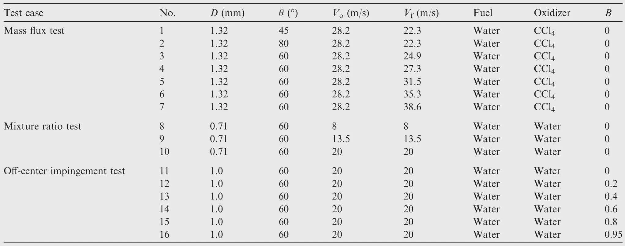
Table 1 Case configurations in three test sets.
Five test cases(No.3–7)with different momentum ratios are studied to verify the momentum characteristics of the spray.The fuel injection velocity holds constant,while the oxidizer injection velocity varies from 24.9 m/s to 38.6 m/s,resulting in a momentum ratio variation from 1.25 to 3.0.When two low velocity jets impinge,a single jet or sheet of liquid is formed and flows in the direction ψ,which is the angle between the coalesced jet and the center line of the two original jets.The angle ψ could be determined using a momentum balance:30
where MR is the momentum ratio of the two jets.Side view of the spray under MR=3.0 is shown in Fig.15(a)and the dependence of angle ψ on momentum ratio is shown in Fig.15(b).The solid line is predicted by the analytical equation,while the discrete points represent the numerical simulation results.It can be seen that the numerical results agree well with the analytical prediction.
4.2.Mixture ratio test
Three test cases of symmetry water jets(No.8–10)with different injection velocities are studied to test the influence of the velocity on the mixture ratio distribution.The fuel orifice and oxidizer orifice are located atx= -5 mm andx=5 mm respectively.The mixture ratio is calculated along the minor axis at a distance of 9.8 cm downstream of the impingement point.The comparison with the experiment30is plotted in Fig.16.At a velocity of 8 m/s,the gradient of the mixture ratio curve is positive,which suggests a bouncing effect.As the velocity increases,the distribution becomes uniform,and at a velocity of 20 m/s,the penetration effect is shown,which indicates that the optimum mixing could be achieved at a velocity a bit larger than 13.5 m/s.It is noticed that the experimental mixture ratio departs from 0.5 at the center of the axis,which is thought to be caused by the experimental uncertainty.In spite of that,the numerical result agrees with the experimental data.
In the normal operation range of liquid rocket engines,the jet velocity varies between 20 m/s and 40 m/s.The analysis above shows that the practical injectors operate in the penetration state,and thus a boost in mixing efficiency could be obtained by reducing the injection velocity.
4.3.Off-center impingement test
Six test cases(No.11–16)with different off-center ratios are studied to verify the influence of the partial impingement.The mass flux is sampled along the plane at a distance of 5 cm under the impingement point.The comparison with experiment36is shown in Fig.17.In the case of perfectly impinging jets,the mass flux distribution shows a symmetry pattern.As the off-center ratio increases,the spray fan(the major axis)rotates around the impingement point.And the dispersion angle along the major axis increases while that along the minor decreases.Besides,a bimodal mass flux distribution is observed.The distance between the two peaks of the mass flux changes slowly as the off-center ratio increases.When the off-center ratio is equal to 0.95,the two jets nearly penetrate each other and the distance between the mass flux peaks is approximately two times that of 0.8.
Because of the collision strategy described in Section 2.3,the current model inherently indicates a sine function between the rotation angle of the major axis and the off-center ratio,as shown in Eq.(44).This is verified by the numerical result.The comparison with experimental data is shown in Fig.18.The rotation angle φ is zero in the perfect impinging case.As the off-center ratio increases,the rotation angle increases by a nearly constant rate.When the off-center ratio approximates 1.0,the rotation angle changes rapidly and finally reaches 90°.An excellent agreement is observed with experimental data.36
The mixture ratio distribution along the major axis is shown in Fig.19.For the perfect impingement,the mixing is uniform along the centerline of the liquid sheet,which is a straightforward result of the symmetry impingement.With the increase of the off-center ratio,the liquid jets penetrate each other,which results in worse mixing.This aspect is critical in liquid rocket engine design.Uneven distribution of propellants leads to non-uniform heat release patterns,which may cause unexpected high temperature regions and low efficiency.
5.Spray characteristics under liquid rocket engine operating conditions
The relationship of the spray characteristics and the injector parameters is studied numerically using the current model inSection 4,and the results agree well with the experiment,which verifies the current model in the quiescent air.However,the liquid rocket engine combustion chamber is featured of high pressure,high temperature and high-velocity gas flows,in which circumstances the impinging spray may show different behavior.Here two sample problems are studied to explore the effect of the liquid rocket engine chamber conditions on the spray mass flux distribution and the mean droplet diameter.The configurations of the computation domain,grid size,boundary conditions and time step are the same with those in Section 4.The orifice diameterDis 1 mm.the impingement angle θ is 60°and the injector upstream pressurep1holds constant 5 MPa.Nitrogen tetroxide is used as the oxidizer and methylhydrazine is used as the fuel.The propellant temperature is 298 K.The physical properties of the propellant are listed in Table 2.
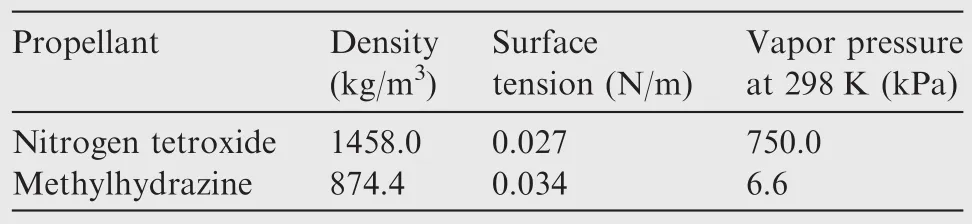
Table 2 Physical properties of propellant.
5.1.Effect of chamber conditions during engine start-up phase
A transient case is studied to explore the spray characteristics during the engine start-up phase.The pressurization in the chamber is simulated by the presumed chamber pressurepcand chamber temperatureTccurves in an equivalent manner,which is shown in Fig.20.Propellant droplets are injected into the computation domain att=0 ms,and the pressure starts to rise att=5 ms.The start-up phase ends att=25 ms and then the chamber conditions remain unchanged.The gas properties such as density and viscosity are calculated through the ideal gas state equation and the Sutherland equation,respectively.
The spray patterns at 5 ms and 25 ms are shown in Fig.21.The orifice operates in the cavitation state at 5 ms,which results in a random transverse velocity component of the large droplets.Therefore,the impingement point oscillates and wider spray dispersion is generated.However,the orifice in Fig.21(b)works in the single phase state.The impingement point holds constant and the distance between the ‘ligaments’is uniform.A worse atomization could be seen in Fig.21(b)as the small child droplet cloud is sparser than that in Fig.21(a).This is verified by the mean droplet diameter change plotted in Fig.22.The mean droplet diameter before 5 ms holds constant at 90 μm because the pressure remains unchanged.As the chamber pressure rises,the mean diameter decreases to a minimum value of 80 μm.This initial decrease is caused by the increase of the gas density.After 8 ms,the effect of the injection velocity decrease prevails over that of the density rise,and then the mean diameter increases to 105 μm.Subsequently,an abrupt decrease to 90 μm occurs and then the mean diameter increases again to a steady value of 120 μm.The orifices before 17 ms operate in the cavitation state and the abrupt change in the diameter is caused by the state transition of the two orifices.Although no experimental data is available because of the difficulty in the measurement of the droplet diameter during the engine start-up phase,the qualitative change of the droplet diameter is deemed to be more reasonable than the constant value in the uncoupled model.16
5.2.Effect of non-uniform gas flow at steady stage
To explore the effect of the gas flow on the spray characteristics,the current study considers the non-uniform gas flow around the injection panel.This gas flow could be caused by the non-uniform heat release in a practical combustion chamber.u,v,zis velocity inX,Y,Zdirection.The velocity boundary in Fig.23 is applied to the bottom face of the computation domain.As a comparison,a case with the uncoupled model16is also tested.In the uncoupled case,child droplets with the diameters equal to those in the coupled case are injected at the impingement point,which is calculated using the geometric parameters.The chamber condition is 4 MPa and 3000 K.
The front and top views are shown in Fig.24.It is clear from Fig.24(a)that the gas flow has little effect on the spray in the uncoupled case:the spray still retains symmetry,the child droplets concentrate around the centerline,and the mixing between oxidizer and fuel droplets is quite uniform.However,distinct difference is shown in the coupled case.The nonuniform gas flow distorts the liquid jets,resulting in an offcenter impingement,as plotted in Fig.24(d).Thus the oxidizer jet and the fuel jet are reflected to the opposite side,leading to spray separation and consequently worse mixing.
The mass flux distribution along the plane 8 cm under the impingement point is shown in Fig.25.Although the pattern in the uncoupled case is nearly the same with that in the quiescent air,the spray fan in the coupled case is rotated by an angle of 38°and the bimodal distribution is clear.
The effect of non-uniform gas flow on the spray characteristics is evident.The comparison suggests that the temperature patterns predicted by the coupled model could be distinct from those predicted by the uncoupled model if the chemical reaction is also considered.And worse mixing will lead to lower combustion efficiency,which is more reasonable than the uncoupled one.
6.Conclusions
A new coupled Lagrangian model is developed to simulate the behavior of the doublet impinging injectors under liquid rocket engine operating conditions.The new model extends the conventional uncoupled model by integrating the plain-orifice sub-model,the liquid jet motion calculation and the jet-jet impingement sub-model.The new model’s ability to predict mass flux and mixture ratio distributions under various injector configurations has been verified by benchmark tests.This model is proved to be able to properly describe the influence of the chamber conditions on the spray.The following conclusions could be summarized:
(1)The study on the spray characteristics during the engine start-up phase shows that the minimum droplet diameter is achieved soon after the chamber pressure rises in the orifice cavitation state.And the atomization during the engine start-up phase is much finer than that in the steady state.For a 4 MPa liquid rocket engine,the minimum droplet diameter is about 30%smaller than the one in steady state.
(2)The non-uniform gas flow around the injection panel in the combustion chamber distorts the liquid jets and leads to an off-center impingement,which changes the spray patterns drastically.For an impingement length of 10 mm and the gas velocity difference of 50 m/s,the spray fan could be rotated by 38°.Besides,the bimodal mass flux distribution and the penetration of the liquid jets lead to poor mixing.
(3)As the jet motion could be predicted,the coupled model suggests more reasonable spray characteristics than the uncoupled one under the changing liquid rocket engine chamber conditions,either in engine start-up phase or steady state.Supposing that the chemical reaction is also considered,the spray characteristics may in turn affect the combustion,and thus the two-way coupling of the combustion and spray could be achieved.
(4)The case verifications in quiescent air have proved that the empirical formulas for the impingement atomization in this paper are suitable for the parameter ranges of most liquid rocket engine cold-flow conditions.Moreover,the empirical formulas have partially considered the effects of gas pressure and velocity on the impingement atomization.Thus,these formulas could be used under complex combustion chamber conditions of liquid rocket engines.
(5)The current model provides a flexible and extendable framework for the impingement spray simulation.As long as more experimental data from cold-flow and hot-fire tests are obtained,the parameters in the model could be calibrated to provide enhanced accuracy for more complex conditions.
1.Ashgriz N.Handbook of atomization and sprays theory and applications.New York:Springer;2011.p.685.
2.Li R,Ashgriz N.Edge instability and velocity of liquid sheets formed by two impinging jets.Atomization Sprays2007;17(1):71–97.
3.Jung S,Hoath SD.Atomization patterns produced by the oblique collision of two Newtonian liquid jets.Phys Fluids2010;22(4):042101.
4.Han Y,Durst F,Zeilmann M.High-pressure-driven twin-jet sprays and their properties.AtomizationSprays2014;24(5):375–401.
5.Sweeney BA,Frederick RA.The effect of liquid jet breakup length on the spray dynamics of like-doublet impinging injectors.Reston(VA):AIAA;2014.Report No.:AIAA-2014-3501.
6.Schumaker SA.The use of X-Ray radiography for measuring mass distributions of rocket injectors.Wright-Patterson AFB,OH:Air Force Research Laboratory;2013.Report No.:0704-0188.
7.Beltran MR.Liquid rocket engine combustion instability studies.Edwards:Air Force Rocket Propulsion Laboratory;1966.Report No.:AD487242.
8.Rupe JH.An experimental correlation of the nonreactive properties of injection schemes and combustion effects in a liquidpropellant rocket engine.Part 1.Pasadena:Jet Propulsion Laboratory;1965.Report No.:N65-33129.
9.Jung K,Lim B.Breakup characteristics of laminar and turbulent liquid sheetsformed by impinging jetsin high pressure environments.Reston(VA):AIAA;2004.Report No.:AIAA-2004-3526.
10.Lu J,Corvalan CM.Influence of viscosity on the impingement of laminar liquid jets.Chem Eng Sci2014;119:182–6.
11.Zheng G,Nie W,Feng S,Wu G.Numerical simulation of the atomization process of a like-doublet impinging rocket injector.Procedia Eng2014;99(2):930–8.
12.Chen X,Ma D,Yang V,Popinet S.High-fidelity simulations ofimpinging jet atomization.AtomizationSprays2013;23(12):1079–101.
13.Khare P.Modeling offinite-size droplets and particles in multiphase flows.Chin J Aeronaut2015;28(4):974–82.
14.Munnannur A,Reitz RD.Comprehensive collision model for multidimensional engine spray computations.Atomization Sprays2009;19(7):597–619.
15.Roth N,Rabe C,Weigand B.Droplet collision outcomes at high weber number.Proceedings of the 21st ILASS-Europe meeting;2007.
16.Ohminami K,Ogawa H.Numerical bipropellant thruster simulation with hydrazine and NTO reduced kinetic reaction model.Reston(VA):AIAA;2009.Report No.:AIAA-2009-0452.
17.Laroslliere LM,Litchford RJ.Hypergolic bipropellant spray combustion and flow modeling in rocket engines.Reston(VA):AIAA;1990.Report No.:AIAA-1990-2238.
18.Prosperetti A.Computational methods for multiphase flow.Cambridge:Cambridge University Press;2007.
19.Morsi SA,Alexander AJ.An investigation of particle trajectories in two-phase flow systems.J Fluid Mech1972;55(2):193–208.
20.Schmidt DP,Corradini ML.The internal flow of diesel fuel injector nozzles:a review.Int J Engine Res2001;2(1):1–22.
21.Taskiran OO,Ergeneman M.Trajectory based droplet collision model for spray.Fuel2014;115(1):896–900.
22.Lai WH,Huang W,Jiang TL.Characteristic study on the likedoublet impinging jets atomization.Atomization Sprays1999;9(3):277–89.
23.Ryan HM,Anderson WE.Atomization characteristics ofimpinging liquid jets.J Propul Power1995;11(1):135–45.
24.Ingebo RD.Drop-size distributions for impinging-jet breakup in airstreams simulating the velocity conditions in rocket combustors.Cleveland:Lewis Flight Propulsion Laboratory;1958.Report No.:NACA TN 4222.
25.Yang LJ,Zhao F.Liquid sheet formed by impingement of two viscous jets.J Propul Power2014;30(4):1016–26.
26.Lee CH,Jung YH,Chung SH.An experiment on flow distribution and mixing in impinging jet sprays.Atomization Sprays1999;9(2):193–213.
27.Gill GS,Nurick WH.Liquid rocket engine injectors.Washington,D.C.:NASA;1976.Report No.:NASA SP-8089.
28.Heidmann MF,Humphrey JC.Fluctuations in a spray formed by two impinging jets.Washington,D.C.:NASA;1951.Report No.:NACA-TN-2349.
29.Rupe JH.The liquid-phase mixing of a pair ofimpinging streams.Pasadena:Jet Propulsion Laboratory;1953.Report No.:AD-0028860.
30.Ashgriz N,Brocklehurst W,Talley D.Mixing mechanisms in a pair ofimpinging jets.J Propul Power2001;17(3):736–49.
31.Zajac LJ.Correlation of spray dropsize distribution and injector variables.California:Rocketdyne;1972.Report No.:N72-18292.
32.Rourke O.Collective drop effects on vaporizing liquid sprays[dissertation].Princeton:Princeton University;1981.
33.Nurick WH.Reactive stream separation photography Final report.Pasadena:Jet Propulsion Laboratory;1971.Report No.:N71-30844.
34.Pischke P,Martin D,Kneer R.Combined spray model for gasoline direct injection hollow-cone sprays.Atomization Sprays2010;20(4):345–64.
35.Marek R,Straub J.Hybrid relaxation—a technique to enhance the rate of convergence ofiterative algorithms.Numer Heat Transfer Part B:Fundamentals1993;23(4):483–97.
36.Gadgil HP,Raghunandan BN.Effect of skewness on the characteristics ofimpinging jet atomizers.Atomization Sprays2009;19(1):1–18.
22 January 2016;revised 4 January 2017;accepted 20 February 2017
Available online 21 June 2017
*Corresponding author.
E-mail address:lgz@buaa.edu.cn(G.LIANG).
Peer review under responsibility of Editorial Committee of CJA.
Production and hosting by Elsevier
http://dx.doi.org/10.1016/j.cja.2017.06.011
1000-9361©2017 Chinese Society of Aeronautics and Astronautics.Production and hosting by Elsevier Ltd.
This is an open access article under the CC BY-NC-ND license(http://creativecommons.org/licenses/by-nc-nd/4.0/).
Combustion chamber;
Doublet impinging injector;
Impingement spray model;
Lagrangian method;
Liquid rocket engine
杂志排行

CHINESE JOURNAL OF AERONAUTICS的其它文章
- Wake structure and similar behavior of wake profiles downstream of a plunging airfoil
- Self-sustained oscillation for compressible cylindrical cavity flows
- Numerical studies of static aeroelastic effects on grid fin aerodynamic performances
- A new vortex sheet model for simulating aircraft wake vortex evolution
- Linear stability analysis of interactions between mixing layer and boundary layer flows
- Aerodynamic multi-objective integrated optimization based on principal component analysis