Numerical simulations of turbulent flows in aeroramp injector/gas-pilot flame scramjet
2017-11-20BingCHENXuXUBoxiWEIYnZHANG
Bing CHEN,Xu XU,Boxi WEI,b,Yn ZHANG
aSchool of Astronautics,Beihang University,Beijing 100083,China
bScience and Technology on Scramjet Laboratory,Beijing Power Machinery Institute,Beijing 100074,China
Numerical simulations of turbulent flows in aeroramp injector/gas-pilot flame scramjet
Bing CHENa,*,Xu XUa,Baoxi WEIa,b,Yan ZHANGa
aSchool of Astronautics,Beihang University,Beijing 100083,China
bScience and Technology on Scramjet Laboratory,Beijing Power Machinery Institute,Beijing 100074,China
To uncover the internal flow characteristics in an ethylene-fueled aeroramp injector/gaspilot(ARI/G-P)flame scramjet,a Reynolds-averaged Navier-Stokes(RANS)solver is constructed under a hybrid polyhedral cell finite volume frame.The shear stress transport(SST)k-ω model is used to predict the turbulence,while the Overmann’s compressibility corrected laminar flamelet model is adopted to simulate the turbulent combustion.Nonreactive computations for Case 1(G-P jet on),Case 2(ARI jets on),and Case 3(both ARI and G-P jets on)were conducted to analyze the mixing mechanism,while reactive Cases 4–7 at equivalent ratios of 0.380,0.278,0.199 and 0.167 respectively were calculated to investigate the flame structure and combustion modes.The numerical results are compared well to those of the experiments.It is shown that the G-P jet plays significant role in both the fuel/air mixing and flame holding processes;the combustion for the four reactive cases takes place intensively in the regions downstream of the ARI/G-P unit;Cases 4 and 5 are under subsonic combustion mode,whereas Cases 6 and 7 are mode transition critical and supersonic combustion cases,respectively;the mode transition equivalent ratio is approximately 0.20.
©2017 Production and hosting by Elsevier Ltd.on behalf of Chinese Society of Aeronautics and Astronautics.This is an open access article under the CC BY-NC-ND license(http://creativecommons.org/licenses/by-nc-nd/4.0/).
1.Introduction
Supersonic combustion ramjet(i.e.scramjet)has long been recognized as one of the most suitable systems for the hypersonic propulsion.Of the special consideration in the development of a scramjet are the efficient mixing and combustion processes,given our limited experience with sustained hypersonic propulsion.Hydrocarbon-fueled scramjet has received considerable attention in recent years due to the high volumetric energy density,low cost,and relative simplicity of operation over hydrogen-fueled one.However,on account of the longer residence time required for mixing and completion of chemical reactions for hydrocarbon fuels,there are still several challenges in the development of a high-performance scramjet.Air and fuel must mix at a molecular level before combustion,so turbulent mixing and combustion are at the heart of scramjet operation.Recently,numerical tools are playing a more and more important role in the predictions of this kind of combus-tion flows.1–5One of the main focuses in these research activities for modeling the turbulent combustion has been the complex interaction between turbulence and chemical reaction.Due to a very short fuel residence time in the combustor,the flame stabilization mechanisms are usually governed by autoignition.Thus,detailed chemical kinetics is usually required to accurately model the ignition and extinction phenomena.3–5
In this case,the traditional species transported finite-rate kinetics method becomes useless for several reasons.First,when a detailed chemical kinetics mechanism is adopted,there will be a large amount of species involved in the species transport equations,which will evoke a vast amount of computational work even beyond thestate-of-the-artcomputer hardware capabilities.Second,to get the chemical source terms in the species transport equations,the Arrhenius law is often used with the turbulence-chemistry interaction ignored,which may cause severe errors.To account for this interaction,some researchers used the eddy dissipation concept(EDC)model6,linear eddy mixing(LEM)model7,transported probability density function(PDF)model8,etc.Third,the coupled Reynolds-averaged Navier-Stokes(RANS)equations and species transport equations are very stiff and difficult to solve accurately due to the strong nonlinearity of the source terms as well as the wide range of time scales associated with both chemistry and turbulence.
One alternative approach to calculate the vast number of species involved hydrocarbon/air turbulent combustion flow is the laminar flamelet model,and there has been extensive research regarding this aspect.1–5,9–15This model successfully separates the chemical time scale and turbulence time scale,allowing the chemistry to be solved independently before the combustion flow computation.The chemistry results can be stored in a tabulated form as a function of a limited number of indexing scalars.During the real-time combustion simulation,just these scalars are needed to be determined in addition to the RANS calculation,while the species transport equations are not needed to be solved anymore.Because the number of the indexing scalars is independent of chemical mechanism,the computational effort is not proportional to the species number.This is very attractive in the detailed chemical kinetics involved combustion flow calculation.
The laminar flamelet model was originally established for the low Mach number turbulent combustion flow,and has been successfully applied to the simulation of turbulent diffusion flames in the subsonic flow.In the supersonic turbulent combustion flow,due to complex flow patterns such as shock waves,contact discontinuities and flame fronts,the model’s applicability is questioned by many experts.The key doubtful point is whether the thickness of the flamelet is really smaller than that of the Kolmogorov vortices or not.But according to the investigations conducted by Bray et al.16,Waidmann et al.17,and Williams18,the combustion in a typical scramjet was approximately in the flamelet regime.More recently,Fan et al.19conducted a careful theoretical and quantitative comparison of these scales in a scramjet combustor and argued that:(A)the flamelet model assumption is valid for the premixed combustion in the recirculation zones and/or the shear layers for all flight Mach numbers;(B)the assumption is also accurate for the non-premixed combustion for most of the flight Mach numbers except for very high Mach number under which the slow reaction mode dominates the combustion.Moreover,several authors have reported successful computations for scramjet turbulent combustions with this model in recent years.1–5,14,15,17,19All these studies confirmed that the laminar flamelet model could model the supersonic turbulent combustion flows very well.
The aim of this paper is to develop a parallel finite volume RANS/flamelet computational fluid dynamics(CFD)code for supersonic turbulent combustion flow and validate the code against the experimental measurements on an an ethylene(C2H4)-fueled aeroramp injector/gas-pilot(denoted as ARI/G-P)flame dual-mode scramjet combustor developed early this decade at Beihang University(BUAA).20–22Wei et al.20,21and Zhang et al.22experimentally studied the operation properties and mode transition influencing factors.It is worth doing careful three-dimensional(3D)CFD simulation to further clarify the flow structure,fuel/air mixing mechanism,and turbulent flame structure,especially to uncover the flow details in the vicinity of the ARI/G-P injection unit and the intensive combustion region.Therefore,the other more important objective of the present study is to numerically investigate the internal flow characteristics in the ARI/G-P combustor.
In the RANS/flamelet simulation,the ethylene/air chemical model23at the University of California at San Diego(UCSD)was used to generate the flamelet table with the FlameMaster24code.The ratio of chemical reaction characteristic time scale to turbulence characteristic time scale was evaluated.Numerical results were analyzed with the main emphasis focusing on the mixing mechanism,flame structure,and combustion mode judgment.
The present paper is organized in the following.Descriptions on the flamelet combustion model,flow governing equations,and numerical algorithm are given in tion 2.In Section 3,the ARI/G-P scramjet combustor configuration and the computation setups(such as computational grids,modeling of G-P jet,chemical reaction model,and boundary conditions)are presented.In Section 4,the numerical results of three nonreactive cases,i.e.Case 1(only G-P jet on),Case 2(only ARI jets on at equivalent ratio of φ=0.380),and Case 3(both ARI and G-P jets on at φ=0.380),are given to analyze the mixing mechanism and the role of the G-P jet.In Section 5,the numerical results offour reactive cases(Cases 4–7)at φ=0.380,0.278,0.199 and 0.167 respectively are presented in detail.Finally,some conclusions are drawn in Section 6.
2.Computational methodology
2.1.Laminar flamelet model
The main assumptions of the laminar flamelet model are as follows1–5,9–15:
(1)The turbulent flame can be regarded as a statistical ensemble of steady laminar diffusion flame structures(named as flamelets)embedded in the turbulent flow field.
(2)Each flamelet can be approximated as a 1D structure(Fig.1)with respect to the mixture fraction according to the laminar diffusion flamelet concept presented by Peters et al.9–11
(3)All chemical time scales are short compared to the smallest turbulent time scale,and the combustion is in equilibrium relative to the turbulence;the thickness scale of a flamelet is short compared to the scale of the smallest turbulent eddies(i.e.,the Kolmogorov vortices),and the inner structure of the flamelet cannot be destroyed by turbulence.
(4)The turbulence influences the flamelets by transporting and twisting them in space;the interaction between turbulence and chemistry can be accounted for with the assumed PDF models.
The 1D structure of a laminar flamelet is illustrated in Fig.1 whereZis the mixture fraction,a general mixing variable representing the relative amount that each inflow stream contributes to the local mixture.Zis also a conserved scalar representing other scalars such as the total enthalpy or a particular element mass fraction.Zstis the stoichiometric mixture fraction.nis the unit normal direction vector to the flamelet surface.The governing equations for the flamelet structure can be obtained from the full 1D species transported Navier-Stokes equations using the low-Mach number asymptotic arguments as9–13
wherepis the pressure,Tis the temperature,ρ is the density,cpis the specific heat capacity at constant pressure,his the enthalpy of the mixture,Yi,hiandWirepresent the mass fraction,enthalpy and molecular weight of speciesirespectively,Rudenotes the universal gas constant,iis the chemical reaction source of speciesiwhich can be determined by the chemical kinetics,χ is the scalar dissipation rate whose reciprocal represents the time scale of the molecular diffusion,andNsis the total number of species.The boundary condition for Eqs.(1)–(4)defined in the mixture fraction space is
where the subscripts F and O represent the fuel and oxidizer stream,respectively.
The Flame Master24code is used to solve Eqs.(1)–(4)to get the two-parameter indexed instantaneous laminar flamelet tables,i.e.Yi(Z,χ)andT(Z,χ).To account for the turbulence effects,the assumed β-and δ-PDF models9–11,25are used to get the Faver-averaged quantities.Subsequently,the tables are parameterized by the mean mixture fractionthe variance of the mixture fraction''2,and the mean scalar dissipation rateas
where the three indexing parameters can be determined by solving the transporting equations ofand''2,and the turbulence model.
To account for the compressibility,only the species mass fractions in the flamelet table are used and the local temperature is calculated implicitly from the total energy1–5in the present context.In other word,the flamelet table is used as a complicated equation of state describing the relation of the local temperature to the compositions,density,pressure,etc.for the compressible CFD solver.1–5,14,17
Assumption(3)is the key point behind the flamelet model approach.In the present research,the ARI/G-P combustor has a relatively low simulated flight Mach number of about 5.0,under which the assumption is believed to be valid.19For the non-premixed flame case,the chemistry time scale τccan be defined as the time scale of the main exothermic reactions in the chemical kinetics system,and can be calculated with10
where χqis the corresponding extinction scalar dissipation rate.The turbulence time scale can be stood for by the Kolmogorov vortices time scale26,τη,
where ν is the kinematic viscosity and ε the turbulent kinetic dissipation.The ratio of the chemistry time scale to the Kolmogorov time scale is defined as the Karlovitz numberKa,
IfKais less than 1.0,the key flamelet assumption is valid.
2.2.Governing equations
2.2.1.Mean flow equations
The mean flow governing equations consist of the conservation equations of mass,momentum and energy,and the transporting equations for the mixture fraction and its variance.In the Faver-averaged form,the system of equations are expressed as
wheretis the time,and U,F(U),G(U)and S are the mean conservation variables,inviscid and viscous fluxes,and source terms,respectively.These vectors are given by
where δij=ei·ej(i,j=1,2,3)is the Kronecker operator,andand ~htare the Reynolds-averaged pressure and Faveraveraged total enthalpy per unit mass,respectively.The viscous stress tensor τij,heat fluxqland operatorlare given by
wherePrtandSctare the turbulent Prandtl number and Schmidt number,respectively,σkis the Prandtl number forkwhich is the turbulence kinetic energy,and μtis the turbulence viscosity.Turbulent parameters can be determined by the(shear stress transport)SSTk-ω turbulence model.27–32Note that the second term on the right-hand side in theqlexpression vanishes under the unity Lewis number(Lel=1)assumption,so the species mass fractions do not need to be explicitly computed.The conductivity κiand viscosity μiof speciesiare determined with the Eucken’s formula24and Lennard-Jones formula24,respectively.The mixture properties such as the viscosity μ,heat conduction coefficient κ,and diffusion coefficientDare computed from the Wilke’s mixing rules.24The specific heat capacitycp,land enthalpyhlare expressed by the polynomial functions of the temperature as follows.24
In Eq.(10),only the~Z''2transport equation has a source term component as
Table 1 Constants used in model.
whereSct2is the turbulent Prandtl number forZ.The scalar dissipation rate,,measures the decay of the mixture fraction fluctuations,and plays forZthe equivalent role of the turbulent kinetic energy dissipation rate ε for the velocity.The associated time scale''2/is often set to be proportional to the turbulence time scalek/ε,which leads to the following expressing:10
whereCχis a constant of order unity.The general equation of state is adopted to close Eq.(10).All the model constants are given in Table 1.
2.2.2.Turbulence model
The turbulence model is very crucial for the numerical simulation in the scramjet engine,especially when transverse injections are involved.27,28The SSTk-ω turbulence model29is one of the most widely used two-equation Boussinesq concept based turbulence models in internal flow simulations.Moreover,the success of this turbulence model used with flamelet model had been proved in Refs.2–5.Therefore,the SSTk-ω model was used in this paper.
This model came from the combination of thek-ω model andk-ε model using a switching function designed by Menter.Consequently,the model is identical to thek-ω model inside the boundary layer and thek-ε model elsewhere.Moreover,the Bradshaw’s assumption,i.e.the principal shear stress is proportional to the turbulent kinetic energy,was used in the deriving of the model.Hence,the model can account for the transport of the turbulent shear stress in turbulent boundary layer,and is very applicable to separated flows in the adverse pressure gradient boundary-layer.Full descriptions of the original SSTk-ω model can be found in Ref.29.
Some modifications reported in the literatures are adopted in the present research.The shear strain rate magnitude|S|is used in the turbulence eddy viscosity expression instead of that of the vorticity,|Ω|.Consequently,the new expression is given by30
where ω is the specific dissipation rate fork,|S|the magnitude of velocity strain rate,a1=0.31 a model constant,andF2a blending function given in Ref.29.This is because there are full of strong shock/boundary-layer interactions(SBLIs),and subsequent separation phenomena in a scramjet combustor,while the original SSTk-ω model has sometimes yielded over-prediction of the separated flow region where strong SBLIs occur.30The modification makes the model be more consistent with the Boussinesq eddy-viscosity assumption,and achieve rotational invariance,which seems to be more rational for SBLIs evoked separation flows.The compressibility correction26,31and low Reynolds number correction26are also used presently.
When the SSTk-ω turbulence model2–5,27–32is used,the mean scalar dissipation rate can be finally modeled as
where the model constant is β*=0.09.The Kolmogorov time scale can be further expressed as19,26
Furthermore,the turbulent Reynolds numberRelis used to check whether the flow is a fully developed turbulence or not.It is defined as19,26
where the integration length scalel=u(l)is the corresponding velocity scale of the energy-containing eddies.It is obvious thatRelis the ratio of the inertial force to the viscous force.Therefore,those vortices withRelgreater than 1.0 are unstable and will gradually break down into smaller scale eddies until the balance between these two forces is established when the eddy scale reaches the Kolmogorov scale.
2.3.Numerical algorithms
The computational domain is meshed with unstructured polyhedral cells,i.e.,a cell element can be a tetrahedron,wedge,pyramid or hexahedron in the grid system for 3D case.The lower-upper symmetric Gauss–Seidel(LU-SGS)implicit algorithm33is employed as the time integration method,and the Harten-Lax-van Leer Contact(HLLC)scheme34as the spatial discretization method.The state parameters on either side of a cell face are reconstructed with a second-order interpolation in conjunction with the Venkatakrishnam slope limiters35–37to maintain monotonicity.The cell center gradients are computed by the Green-Gauss theorem,whereas the normal gradients at a cell face are approximated as in Refs.5,35,36.The SSTk-ω turbulence model27–32is solved separately after each timestepping of the RANS equations.In the implicit integration process for both the turbulence and fluid motion equations,the local time step method is used to determine the time step Δtfor each cell.
3.ARI/G-P model and computation setup
3.1.ARI/G-P combustor model description
The ARI/G-P combustor sketched in Fig.220–22consists of 6 segments with a rectangular cross-section.The top and bottom walls are parallel to each other with a height of 32 mm,while the other two side walls are divergent at angles of 1.14°,6°,1.4°,3.2°,1.2°and 12°for each segment.The entrance and exit dimensionsare32 mm×54 mm and 32 mm×145 mm,respectively.Segment 1 is used as an isolator.The integrated ARI/G-P injection unit,consisting of an aeroramp injector(ARI)and a gas-pilot(G-P)flame,is located on the bottom wall,and plays as the injection,ignition,and flame holding device.The ARI is composed offour flush-wall sonic fuel jets arranged in a two-by-two matrix pattern.The jets are set at prescribed transverse(pitch)angles of 20°and 40°,and toein(yaw)angles of 15°and 30°.The ARI unit has an equivalent diameterdeq=2.8 mm,which is defined asdeq=dj·m0.5,wheredj=1.4 mm is the diameter of each injector andmis the total number of the injectors.The space between injectors is 4deqin the streamwise direction and 2deqin the spanwise direction.The G-P flame,a kerosene/oxygen combustion jet with a diameter ofdg=5 mm,is placed 8deqdownstream of the ARI jet center.
Several reactive and nonreactive experiments on this scramjet had been performed in the direct-connect supersonic combustion facility at BUAA.20–22In the reactive tests,the high enthalpy vitiated air was heated by a hydrogen-oxygen heater,entering the isolator with a Mach number ofMa=2.0,and a static pressure of 0.115 MPa which is used as the reference pressure asp0.The ethylene(C2H4)was injected into the combustor at a Mach number of 1.0 and total temperatureTtof 300 K.The G-P chamber pressure was about 0.9 MPa.The side wall centerline values of pressure were measured.Detailed conditions of the ethylene jets,vitiated air,and G-P flame are summarized in Tables 2 and 3.In the nonreactive experiments,both the ARI ethylene jets and G-P flame jet were replaced with nitrogen at the same momentum flux ratios as those in the reactive cases.Wall oil flow visualization and Schlieren images in the ARI/G-P adjacent region were obtained.More information regarding these ARI/G-P combustor ground experiments can be found in Refs.20–22.
3.2.Computation setup
3.2.1.Computational grids
An unstructured storage multi-block hexahedron grid system was used for accuracy consideration,although the present CFD code is based on the unstructured hybrid grid.Only half of the model was taken into consideration.Three computational grids,consisting of 2.5 million(coarse),4.78 million(medium),and 7.66 million(fine)cells,respectively,were used to verify grid convergence.The medium grid is presented in Fig.3.The coordinate origin was set at the centroid point of the first row of aeroramp injectors,thex-,y-andzcoordinate were along the combustor main flow direction,the spanwise direction,and the direction normal to the ARI/G-P unit wall,respectively.Each ARI injector and G-P injec-tor were modeled as cylinders with lengths ofLi=3.57deqandLg=2.86deq,respectively.A five-block butterfly-topology was adopted for each fuel injector,and a four-block one for the half G-P injector.Grid cells were refined in the wall-normal direction.Three grids were partitioned into subdomains for the message-passing-interface(MPI)-based parallel computations by MeTiS38which is an open source software package for partitioning unstructured grids based on a multilevel graph partitioning algorithm.
Table 2 Free stream conditions of ethylene jets and vitiated air.
Table 3 Parameters of G-P flame.
3.2.2.Modeling G-P flame jet
Previous research had uncovered that the G-P jet plays several key roles for the ARI/G-P combustor20–22:
(1)It enhances the fuel/air mixing remarkably.The G-P jet lifts up the ARI plume greatly,which leads to an obviously large fuel penetration height,big plume area,and subsequently high mixing efficiency.
(2)It acts as an igniter.The high enthalpy G-P gas,as the kerosene/oxygen combustion product with a total temperature of 3000 K,is a continuous pilot torch flame for the C2H4/air combustion.
(3)It also operates as a flame holder.There are several recirculation zones generated by the interactions among the ARI and G-P jets.The one pilot torch plus several recirculation zones flow pattern is the root offlame holding capability of the ARI/G-P injection unit.
Theoretically,all properties of the G-P gas should be simulated accurately.Unfortunately,the laminar flamelet model can only cope with a two-stream combustion system.1–5,9–15
To overcome this obstacle,the G-P flame was simply modeled as a hot stream with the same species composition of the vitiated air.Therefore,the chemical composition and high enthalpy effects of the G-P gas on the chemical mechanism were neglected.To the best of our knowledge,the overall simulation accuracy does not deteriorate.There are two known supporting factors.First,the G-P flame mass flow rate is relatively small compared to that of either the fuel or the main air stream.Second,previous experiments have demonstrated that the overall combustion efficiency is not sensitive to the G-P momentum flux ratio21,illustrating that the G-P stream does not influence the chemical process significantly.
3.2.3.Chemistry mechanism and flamelet table
The UCSD ethylene/air chemistry model23,consisting of 34 reactions with 19 species,was used in the flamelet table generation.Here,theLel=1 condition for all species was assumed.The background pressure was chosen at approximately 1.5×10⁵Pa.The temperature was set at 730 K for the oxidizer stream and 300 K for the fuel stream.The table included 56 laminar flamelets with the scalar dissipation rate varying from χ1=0.1 s-1to χq=1061.0 s-1,which led to an upper bound of 30 K for the discrepancy between the peak temperatures from flamelet to flamelet.The laminar flamelet table was further convoluted with the assumed β-PDF and δ-PDF25applied toZand χ,respectively.Then the final chemical species were subsequently tabulated with respect to three mean variables,i.e.,'2andχ.
3.2.4.Boundary conditions
The flow at the ARI/G-P combustor entrance is supersonic,so all flow variables were fixed under the free stream condition of the vitiated air.Mass flow inlet conditions were applied for both the ARI and G-P jets.The entrance boundary-layer had been ignored.Supersonic extrapolation condition was adopted at the combustor outlet boundary.Mirror reflection condition was implemented on the symmetry boundary.On the wall,no-slip velocity,adiabatic temperature,and zerogradient pressure conditions were imposed.The density on the wall was obtained from the equation of state.
The mixture fractionZwas fixed at 0 at the entrances of both the air stream and G-P jet,and at 1.0 at the ARI injector entrances.Extrapolation condition for the mixture fraction variance was applied on open flow boundary.On the wall,the zero-gradient extrapolation Z condition and''2=0 were imposed.
The turbulent kinetic energy was fixed to a turbulence intensity ofTu=4%for the air stream,andTu=5%for both the ARI and G-P jets.The turbulence kinetic energy dissipation rate was based on the integration length scalel0=k1/2/(β*ω)using the corresponding hydraulic diameter.Then,the specific dissipation rate can be calculated through ω = ε/(β*k).On the wall,kw=0,and
where ωwis the turbulent dissipation rate forkat the wall,andd1the normal distance of the cell center away from the wall.
Table 4 Three typical nonreactive cases.
4.Nonreactive results
Three typical nonreactive cases listed in Table 4 were calculated to investigate the mixing mechanism.Only G-P valve was turned on for Case 1,and ARI valve for Case 2,whereas both valves were open for Case 3.The equivalent ratio was φ=0.380 in Cases 2 and 3.Grid convergence study was performed for Case 3.
4.1.Grid convergence
The pressure profiles obtained on three grids are presented in Fig.4.The pressurepincreases slightly in the isolator due to the viscous effect in the boundary-layers,and decreases abruptly at aroundx/deq=-71.4 for the wall expansion from Segment 1 to Segment 2.Another obvious pressure decrease occurs at approximatelyx/deq=-28.0,where the expansion waves originating from the opposite wall impinge on the side wall.Then,the pressure abruptly increases at aboutx/deq=13.5 as a result of the impingement of the merged bow shock.Downstream of the strong shock/boundary interaction region,the pressure turns back rapidly at aboutx/deq=41.0,followed downstream by a geometry divergence resulted overall gradually decrease with several wiggles.It is obvious that the pressure discrepancies from the coarse grid through the fine grid are relatively small,indicating that good grid convergence has been achieved.
Furthermore,the grid convergence index(GCI)devised by Roache39and also cited by Wilcox32was used to evaluate the accuracy regarding the grid resolution.For a given flow property ψ,the GCI is defined as39
where εhis the relative difference between two grids for ψ,rthe fine-to-coarse grid point ratio,andathe spatial algorithm order.
The GCI values of 9 flow variables at pointsA(xA/deq=53.6)andB(xB/deq=253.6)from the medium grid to fine grid are presented in Table 5.PointsA(entrance center of Segment 3)andB(entrance center of Segment 5)locate in the ARI/G-P adjacent and far downstream regions,respectively.The grid point ratio isr=7.66/4.78≈1.602.The numerical method order is approximatelya=2.Table 5 reveals that the maximums of the GCIs are less than 2%at both points.Therefore,it can be claimed that the GCIs for all flow properties remain the same low level throughout the flow field,which illustrates that the cold flow computations on the medium grid are of good accuracy.
4.2.Results and discussion
4.2.1.Flow structure comparison
Fig.5 presents the numerical and experimental Schlieren images in the ARI/G-P adjacent region.The separationstreamlines and sonic lines are also plotted.It should be noted that though the ARI jets for Case 1 and G-P jet for Case 2 were closed,the same computational grid as that for Case 3 was used except that the entrances of the ARI jets and G-P jet were treated as no-slip,no-penetration walls for Cases 1 and 2,respectively.Therefore,the four blinded ARI injector tubes act as low length/depth ratio cavities for Case 1,while the blinded G-P tube for Case 2.
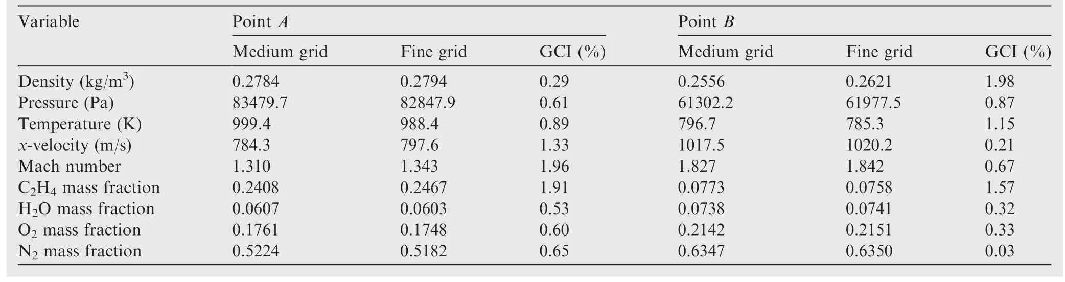
Table 5 Grid-resolution results at entrance centers of Segments 3 and 5(r=1.602,a=2).
In Case 1,the under-expansion G-P jet enters the main stream normally,accelerated out of the G-P tube,and generates a barrel shock and Mach disk.Due to the barrel shock blockage,upstream of the G-P jet originates a strong detached bow shock,which is so strong that the downstream flow is subsonic near the bottom wall.The bow shock interacts with the boundary-layer,generating a strong adverse pressure gradient which propagates upstream through the boundary-layer.Consequently, a relatively large scale boundary-layer separation bubble is generated with a separation shock emanating from its leading-edge.The separation shock impinges and merges with the bow shock.When the bow shock hits the top wall,another boundary-layer separation bubble with a leading-edge separation shock attached is produced.A shear layer between the jet plume and surrounding stream is also generated.Consequently,severalsubsonic bubbles are generated.
In Case 2,two bow shock waves are formed due to the blockages of the ARI fuel jets.The strengths are relatively weak due to the streamwise-biasing angled injections.Therefore,the boundary-layer separation bubbles are small,and the attached separation shocks are weak.Some noise can be seen apparently in the G-P exit adjacent region due to the blinded G-P hole effect.
Case 3 is a combination of Cases 1 and 2.The bow shocks and separation bubbles evoked by the ARI jets are the same as those in Case 2.Because the air flow has been altered by the ARI jets,the flow pattern is a little different from Case 1 downstream of the ARI jets:(A)the separation bubble upstream of the G-P barrel shock is not clear;(B)the edge between the barrel shock and shear layer is not clear either;(C)the shapes of the subsonic bubbles upstream of the G-P jet,downstream of the barrel shock and Mach disk,are also altered apparently.
A reasonable level of agreement has been achieved between the numerical and experimental schlierens generally.However,due to the influence of the turbulence model,two obvious discrepancies exist:(A)the numerical bow shock wave for Case 1 is displaced slightly in thex-direction;and(B)the numerical boundary separation bubble upstream of each jet is slightly larger.
The flow structure in the ARI/G-P adjacent region is further illustrated by the wall friction streamlines in Fig.6.The numerical flow topology is quite similar to that of the experiment.The incoming flow is blocked by the ARI/G-P jets successively,making the streamlines deviate transversely.The numerical reattachment line angle is a little larger.Two pairs of counter-rotating zones are formed just upstream of the G-P jet.These recirculation zones and their successive downstream structures play a positive role not only to the fuel/air mixing,but also to the flame holding of the following reactive cases.
4.2.2.ARI/G-P jets mixing mechanism
The ethylene mass fraction(YC2H4)and streamlines in 8xplanes for Case 3 are presented in Fig.7.In thex/deq=0 plane,the fuel penetration height is relatively small,i.e.z/deq<1.0.Both jets have a 20°injection angle of pitch and a 15°angle of yaw in the opposite direction,which results in two relatively small counter-rotating vortices,uplifting the fuel plume and enhancing the fuel/air mixing.In thex/deq=4 plane,another two fuel jets with a 40°angle of pitch and a 30°angle of yaw inject into the flow stream,interact with the first two and intensify the fuel/air mixing further.Fig.7(d)reveals that two groups of jet plumes mix perfectly in the transverse direction,and merge into a relatively large-scale fuel plume at the mid-plane atx/deq=7.The scale of the counter-rotating vortices is also enlarged apparently.At thex/deq=10 plane,the G-P jet normally injects into the combustor at a mass flow rate of 17 g/s,resulting in a relatively large penetration height ofz/deq>8.When the fuel plume interacts with the G-P jet,the fuel plume is highly uplifted and the counter-rotating vortices are pushed aside to the two opposite sides of the G-P jet.Downstream of the G-P jet the two vortices rapidly move close,and the scale is enlarged significantly,during which the fuel plume mixes intensively with the air stream due to the entrainment of the vortices.
Fig.8 presents the ethylene mass fraction for Case 3 in threez-planes atz/deq=0,2.857 and 5.714,respectively.It is shown that in thez/deq=0 plane the fuel jets are blocked and split by the G-P jet,making the fuel plume scale increase rapidly in they-direction.Downstream of the G-P jet,ethylene quickly fills the wake region.In Figs.7 and 8,the C2H4mass fraction iso-lines atYC2H4=1.0×10⁵and 0.001 are used to show the edge of the fuel plume,whereas the one atYC2H4=0.068 is used to illustrate the ethylene/air stoichiometric location.It is apparent that due to the interactions among the ARI and G-P jets,(A)the fuel plume scale increases continuously in the transverse direction,and(B)the peak fuel concentration decays rapidly along the streamwise direction.
To further clarify the G-P jet role,numerical results in fourx-planes for both Cases 1 and 2 are given in Fig.9.The flood contour variable for Case 1 is chosen as the static temperature to identify the hot G-P jet plume approximately for there was not any fuel injected,while the C2H4mass fraction is used as flood contour variable for Case 2 for convenient comparison to Fig.7.It is shown that the G-P jet in Case 1 and ARI jets in Case 2 separately generate a pair of counter-rotating vortices whose rotating direction is consistent to each other.When these two pairs of vortices interact and overlap,the vortices’structures for Case 3 are generated,and the fuel/air mixing is enhanced.Consequently,the fuel plume area of Case 3 is much larger than that of Case 2,indicating that the mixing efficiency of the ARI/G-P unit is much better than that of the pure ARI unit.
5.Reactive results
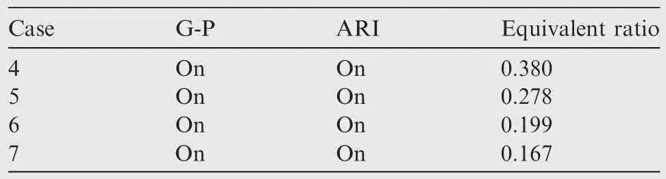
Table 6 Four typical reactive cases.
Then,four typical reactive cases in Table 6,i.e.Cases 4–7 at φ=0.380,0.278,0.199 and 0.167,respectively,were calculated to demonstrate the flow structure,flame structure,and combustion mode.The corresponding experimental results had been published in Refs.20–22.
5.1.Reactive cases at φ=0.380
5.1.1.Flow characteristics
Fig.10 presents the static pressure,Mach number,and the sonic lines in the combustor symmetric planes.Due to the heat addition,a relatively large adverse pressure gradient is generated and propagates upstream through the wall boundarylayer,pushing the main air stream aside from the wall in the transverse direction.Consequently,the effective supersonic core flow passage in Segment 2 looks like a convergentdivergent-convergent-divergent(C-D-C-D)tube,and there is a large subsonic flow region in Segments 2 and 3.This subsonic region is much larger than that in Case 3.Downstream of the G-P jet,the Mach number increases due to the combustion heat releases.The flow gets to the thermal choking state at around the Segment 3/4 conjunction station.The sonic lines reveal that the thermal choking line looks like a ‘W” aligning in the streamwise direction in thez/deq=5.714 plane.For the geometry compression,weak oblique shock waves originate at the entrance of Segment 5,and interact intensively with the side wall boundary-layers,leading to a complex oblique shock train structure.
Fig.11 further plots the centerline and averaged total temperatureTt,c,Tt,avand Mach numberMac,Maavdistributions.The Mach number in the isolator is around 2.0,and the centerline Mach number increases to 2.16 at aboutx/deq=-55.0 for the geometry expansion.When the air flows through the C-D-C parts(-37.2≤x/deq≤-0.2)of the boundary-layer altered effective passage,the Mach number profile exhibits an increase-decrease-increase variation characteristics.Then,the air stream interacts with the ARI and G-P jets successively in the last divergent part where the combustion originates.Due to the combined effects of the geometry divergent,air/jet interactions,and heat release,the flow rapidly turns to subsonic,and the centerline Mach number reachesMa=0.23 at aboutx/deq=24.9.Two wiggles on the Mach number profile exist near the air/jet interaction positions.Downstream of the ARI/G-P unit,the Mach number keeps increasing for heat addition and/or geometry expansion except a slight decrease in Segment 5 for viscous effect.
The total temperature distributions indicate that the heat releases intensively in the subsonic region.That is to say the chemical reaction mainly takes place in this subsonic region,and hence subsonic combustion is the leading combustion mode.This coincides with the experimental conclusion drawn in Refs.20,21.
The pressure profiles along the side wall centerline for Case 4 are presented in Fig.12.In Fig.12(a),the pressure distributions obtained on three grids agree well with each other,although there are some small discrepancies.Numerical results on the coarse grid exhibit an apparent unreasonable local peak pressure in Segment 5.This is because the wall-normal grid resolution of the coarse grid is too poor to accurately capture the complex SBLIs.Due to space limitation,further GCI analysis on the reactive case is not presented.Generally speaking,a good grid convergence has also been accomplished for the reactive case.Fig.12(b)reveals that the present numerical results agree well with those of the experiment,and the peak pressure is captured accurately,whereas the original point of numerical pressure rise and the overall peak pressure presented by Wei et al.20are a little more upstream than those of the experiment.
5.1.2.Flame structures
Because turbulence stochastically twists and transports each individual flamelet,the instantaneous turbulent flame often exhibits strong unsteadiness,and is quite complicated in practice.Fortunately,the mean flame as a whole usually remains stationary at a certain fixed position.39The high hydroxyl(OH)radical concentration regions can be used to stand for the mostintensive combustion regions approximately.Fig.13 gives the numerical OH concentrationYOHand total temperature distributions in the symmetric planes.Three isolines are also plotted at=0.048,0.068 and 0.088,respectively,wherest=0.068 is the stoichiometric mixture fraction.It is apparent that(A)the high OH concentration region is consistent with the high total temperature region(i.e.the flame core);(B)the flame core falls into the relatively narrow range of 0.048≤≤0.088 withstbeing the centroid point.
The mixedness and flame index40are used to further investigate the flame structure in the ARI/G-P combustor.The mixednessZFOis a measure of the mixing extent of the unburned fuel with oxygen coming from the surrounding air.It is defined as40
wherefstis the stoichiometric oxygen-to-fuel mass ratio.Obviously,ZFOis positive in the fuel-rich region and negative in the fuel-lean region.The absolute value ofZFOincreases as the mixedness increases.
The flame index(denoted asGFO)is designed to distinguish premixed flame from non-premixed diffusion flame.40It is defined as the dot-product of the mass fraction gradients of both fuel and oxygen,
The sign ofGFOrelies on the relative supplying directions offuel and oxygen.The fuel and air come from the opposite direction for a typical non-premixed diffusion flame,whereas both of them come from the same direction for a typical premixed flame.Therefore,the flame indexGFOis positive for a premixed flame and negative for a diffusion flame.A high value of|GFO|means a rapid supplying rate offuel and oxygen by molecular diffusion.
The mixedness and flame index distributions in thez/deq=5.714 plane are presented in Fig.14.ZFOevenly distributed in[-0.03,0.03];GFOexponentially distributed in[-2000.0,0),while evenly in(0,70.0].Fig.14(a)reveals that there is a large amount offuel left unburned in the flow region downstream of the ARI/G-P jets.In Fig.14(b),the negative flame index is plotted in colored floods with its magnitude being exponentially distributed,while the evenly distributed positive flame index is shown in gray floods.Three iso-lines atGFO=-1,-10 and-20 respectively are also included.It is shown that the flame index is negative in almost all the intensive combustion region.Therefore,the flames in the combustor are mainly diffusion flames.Near the ARI/G-P joint jet stream,there are some small scattered positiveGFOregions where the flames are premixed flames.These well premixed flame regions are generated by the entraining mechanism39of the large-scale counter-rotating vortices.Generally speaking,the complex flame structure is illustrated very well by theGFOdistributions and non-premixed flame is the pronounced flame type in the combustor.
Furthermore,Fig.15 gives the mixedness and flame index plots in 8x-planes to clarify the streamwise evolution characteristics.ZFOevenly distributed in[-0.03,0.03];GFOexponentially distributed in[-2000.0,0),while evenly in(0,70.0].Upstream of the G-P jet,a large negativeGFOzone with|GFO|>2000.0 is generated since the fuel injects into the main air stream.This means a rapid supplying rate offuel and oxygen by molecular diffusion due to their large gradients from the opposite direction.Consequently,a typical non-premixed flame structure is formed.Then,the thin fuel/air shear layer flame interacts with the G-P jet introduced atx/deq=10.0.Downstream of the G-P jet,due to both the intensified fuel/air mixing and fuel/oxygen combustion consumption,the absolute value of the negativeGOFrapidly decreases while the zone length scale gradually increases in the transverse direction.As a result,the fuel/oxygen molecular diffusion rates decrease rapidly.A rapid decrease rate of theZFOabsolute value along the streamwise direction is also clearly exhibited.There are also some small regions with positiveGFOin the core flow for the entraining role of the vortex motion.Some small well-mixed regions are also generated in the boundary-layer where the vortices hit the bottom wall;hence,several small premixed flame regions are formed(see Fig.15(e)–(h)).
5.1.3.Characteristic scales
Only the characteristic scales on thest=0.068 iso-surface are taken into consideration because the most intensive chemical reaction mainly takes place near the stoichiometric regions.The turbulence Reynolds numberReland Karlovitz numberKa distributions on the stoichiometric surface are presented inFig.16.It is shown thatthe turbulence Reynolds numberRelis much larger than 1.0 on almost all the surface except a relatively small part near the bottom and top walls whereRelis near 1.0.This implies that the combustion takes place in the fully developed turbulence flow regions for Case 4.As also shown in Fig.16,the Karlovitz numberKaon the stoichiometric surface is much less than 1.0,which means the chemical time scale is much shorter than the Kolmogorov vortices time scale.This generally further indicates that the combustion for Case 4 is in equilibrium relative to the turbulent time scale;hence the key assumption on flamelet is held.
Fig.16 reveals that the stoichiometric mixture faction surface mainly stays in the large-scale subsonic region shown in Fig.10,but a relatively small rear part extends into the supersonic region.Therefore,though Case 4 is a subsonic combustion dominating case,the intensive combustion takes place not only in the subsonic region but also in the supersonic flow region.
5.2.Other equivalent ratio cases
Cases 5–7 were further simulated on the medium grid to study the fuel mass flow rate influence.Fig.17 presents the OH mass fraction floods,sonic lines,and stoichiometric iso-line at=0.068 for Cases 4–7.Due to different equivalent ratios and hence different amounts of heat release,the flow structures are different from case to case.In all the four reactive cases,the subsonic regions downstream of the G-P jet are enlarged for the heat addition.As a result,the static pressure rapidly increases,and produces an adverse pressure gradient which in turn prompts the generation of subsonic bubbles near the combustor wall, or even evokes the boundary-layer separations.In Case 7,the heat release amount is relatively small,so the resulted adverse pressure gradient is not large enough to generate subsonic flow bubbles near two divergent side walls.However,in Case 6,due to the increase in heat release compared to Case 7,the pressure increment is high enough to generate a small subsonic flow region near each side wall.The flows are still supersonic between the side wall subsonic bubbles and the core subsonic region downstream of the G-P jet.From Case 6 to Case 5,both the side wall subsonic bubbles and the core subsonic flow region are enlarged for more heat release.When fuel mass flux and heat release increases to the level of Case 4,the side wall subsonic bubbles and the core subsonic flow region are enlarged to merge into one large subsonic region.It is shown that the critical equivalent ratio at which the side wall subsonic bubble originates is approximately 0.20,which is consistent with the conclusion drawn in Ref.21.All the stoichiometric lines for the three low equivalent ratio cases are in the G-P jet downstream subsonic flow regions where the chemical reaction takes place intensively.
The flame structures for Cases 5–7 are illustrated by the flame index distributions in Fig.18.GFOexponentially distributed in[-2000.0,0),while evenly in(0,70.0].It is shown that all the three are non-premixed flame dominating cases because the negativeGFOflood almost fulfills the combustion regions.There are also some scattered premixed flame regions(denoted by positiveGFO).The flame structures are similar to that for Case 4(Fig.14),but the combustion zone length scale in the streamwise direction becomes shorter and shorter from Case 4 to Case 7.In Fig.18(b),the premixed flame zone in thez/deq=5.714 plane is split into several scattered spots due to the occurrence of the edge-wiggled side wall subsonic bubble(Fig.17(c)).
Fig.19 further plots the pressure distributions along the side wall centerline for the three low equivalent ratio cases.In general,the numerical results agree well with those of the experiments,although there are some differences.The numerical original points of pressure rise for the three cases are slightly upstream than those of the experiments,but the numerical result of Case 4 agrees well with that of experiment(Fig.12(b)).It is probably because there might be some kinds of flame lifts which cannot be accurately captured by the steady flamelet model.It also may be the results of the turbulence model influence.
5.3.Combustion mode
Although the combustion mode has been studied for a long time22,41–43,there is not any generally accepted criterion to classify the combustion mode yet.Different conclusion would probably be drawn according to different classification criteria for a given case.One widely used method is based on the minimum of the 1D Mach number.Wei et al.20,21applied this method to the ARI/G-P combustor,and concluded that one case at an equivalent ratio φ≤0.26 was under supersonic combustion mode(e.g.Cases 6 and 7).Zhang et al.22pointed out that the conclusion was strongly influenced by the accuracy of the 1D result.Here,to further study the ARI/G-P combustion mode,not only the 1D Mach number but also the static pressure rise position relativeto injector43are taken into consideration.
Fig.20 presents the passage centerline Mach number for Cases 3–7.Only the first three segments of Case 3 are plotted.It is apparent that the reactive Mach number profiles are identical to the nonreactive upstream of the original point to decrease.But the original points for Cases 4–7 are different:the original points for Cases 6 and 7 are both at approximatelyx/deq=6.2 even though different amounts of heat are added,whereas,for Cases 4 and 5,the original points are at aboutx/deq=-39.1 and-14.9,respectively.This indicates that there is a threshold value for the heat amount to let its influence propagate to the upstream area of the ARI injectors,and the critical case is Case 6.
Fig.21 further presents the mass-flow-weighted total temperature,Mach number and static pressure profiles for the five cases.It is shown that the original points of total temperature rise are almost at the samex-station of aboutx/deq=6.2,although the peak total temperature decreases from Case 4 to Case 7.This phenomenon indicates that the combustion(and hence heat release)originates from the samex-position for the four reactive cases.However,the original points of pressure rise are very different:(A)the original points of Cases 4 and 5 are atx/deq=-50.7 and-30.1,respectively,both of which are upstream of the fuel injectors;(B)those of Cases 6 and 7 are almost at the same position of aboutx/deq=2.6 which is slightly upstream of the total temperature rise point but still downstream of the fuel injectors.The original points of Mach number decrease are the same as those of the pressure rise for each reactive case.It is obvious that the minimums of the averaged 1D Mach number for Cases 4 and 5 are less than 1.0,while that of Case 7 is larger than 1.0,and Case 6 is a critical case.
Both Figs.20 and 21 indicate that(A)Cases 4 and 5 are under subsonic combustion mode,while Case 7 is a typical supersonic combustion case,and Case 6 is approximately a critical transition mode case;(B)the mode transition equivalent ratio is about 0.20,which is lower than that in Ref.20.
6.Conclusions
The flow in the ethylene(C2H4)-fueled ARI/G-P scramjet combustor at BUAA has been calculated with a parallel RANS/Flamelet Code,in which RANS equations,SSTk-ω turbulence model,and the two scalar transport equations are solved with the LU-SGS time algorithm and HLLC spatial scheme under a hybrid polyhedral cell finite volume frame.The compressibility corrected steady flamelet model with the assumed PDF models to account for the interaction between turbulence and chemistry is used to simulate the turbulent combustion.Three nonreactive and four reactive cases are simulated.Pressure distributions and GCIs calculation on three grids with different resolution have been performed.Numerical results show that good grid convergences have been achieved for both nonreactive and reactive cases.Numerical results(such as wall pressure distributions,Schlieren images and viscous streamlines)are compared well with those of the experiments published before.
The mixedness and flame index are calculated to analyze the turbulent flame structure in the ARI/G-P combustor.It is proved that the turbulent flame offour reactive cases is dominated by diffusion flame,although there are some small scattered premixed flame spots embedded in the core flow and bottom wall boundary-layers downstream of the G-P jet.The intensive combustion region is proved to be nearthe stoichiometric mixture fraction,andfalls into the narrow range from=0.048 to 0.088.The turbulence Reynolds number and Karlovitz numberdistributions on the stoichiometric isosurfaces indicate that flows in the intensivecombustionregion are infully developed turbulent state and the chemical time scale is short compared to the smallest turbulent time scale.It is also shown that the combustion in the ARI/G-P downstream flow regions is intensive for all the four reactive cases,and the G-P jet plays significant role in both the fuel/air mixing and flame holding processes.
The passage centerline Mach number and mass-flowweighted average profiles indicate that Cases 4 and 5 are under subsonic combustion mode,whereas Cases 6 and 7 are mode transition critical and supersonic combustion cases,respectively.It is proved that the mode transition equivalent ratio is about 0.20,which is the same as the critical equivalent ratio for the side wall subsonic bubble occurrence.This implies that the mode transition of the combustor takes place when the relative large-scale side wall subsonic bubble occurs.
Acknowledgments
This study was co-supported by the National Natural Science Foundation of China(Nos.51176003 and 51276007),and the Fundamental Research Funds for the Central Universities of China(No.YWF-15-GFY).
1.Oevermann M.Numerical investigation of turbulent combustion in a scramjet using flamelet modeling.Aerospace Sci Technol2000;4(7):463–80.
2.Gao ZX,Lee CH.A flamelet model for turbulent diffusion combustion in supersonic flow.Sci China:Technol Sci2010;53(12):3379–88.
3.Pecˇnik R,Terrapon VE,Ham F,Iaccarino G,Pitsch H.Reynoldsaveraged Navier-Stokes simulations of the HyShot II scramjet.AIAA J2012;50(8):1717–32.
4.Pecˇnik R,Terrapon VE,Ham F,Iaccarino G.Full system scramjet simulation.CRT Ann Res Brief2009;33–46.
5.Terrapon VE,Han F,Pecˇnik R,Pitsch H.A flamelet-based model for supersonic combustion.CRT Ann Res Brief2009;47–58.
6.Chakraborty D,Paul P,Mukunda H.Evaluation of combustion models for high speed H2/air confined mixing layer using DNS data.Combust Flame2000;121(1–2):195–209.
7.Ge´nin F,Chernyavsky B,Menson S.Large eddy simulation of scramjet combustion using a subgrid mixing/combustion model.12th AIAA international space planes and hypersonic systems and technologies;2003 December 15–19;Norfolk,USA.Reston(VA):AIAA;2003.
8.Baurle R,Hsu A,Hassan H.Assumed and evolution probability density functions in supersonic turbulent combustion calculations.J Propul Power1995;11(6):1132–8.
9.Peters N.Laminar diffusion flamelet models in non-premixed turbulent combustion.ProgEnergyCombustSci1984;10(3):319–39.
10.Peters N.Turbulent combustion.Cambridge:Cambridge University Press;2000.
11.Peters N.Laminar flamelet concepts in turbulent combustion.Twenty-firstsymposium(international)oncombustion,21(1)1986.p.1231–50.
12.Pierce CD,Moin P.Progress-variable approach for large-eddy simulation of non-premixed turbulent combustion.J Fluid Mech2004;504:73–9.
13.Ihme M,See YC.Prediction of autoignition in a lifted methane/air flame using an unsteady flamelet/progressvariable model.Combust Flame2010;157(10):1850–62.
14.Saghafian A,Shunn L,Philips DA,Ham F.Large eddy simulations of the HIFiRE scramjet using a compressible flamelet/progress variable approach.ProcCombustInst2015;35(2):2163–72.
15.Saghafian A,Terrapon VE,Pitsch H.An efficient flamelet-based combustion model for compressible flows.CombustFlame2015;162(3):652–67.
16.Bray KNC,Libby PA,Williams FA.High speed turbulent combustion.In:Libby PA,Williams FA,editors.Turbulent reacting flow.New York:Academic Press;1994.
17.Waidmann W,Alff F,Bo¨hm M,Brummund U,Clauβ W,Oschwald M.Supersonic combustion of hydrogen/air in a scramjet combustion chamber.Space Technol1996;15(6):421–9.
18.Williams FA.Progress in knowledge offlamelet structure and extinction.Prog Energy Combust Sci2000;26(4–6):657–82.
19.Fan ZQ,Liu WD,Sun MB,Wang ZG,Luo WL.Theoretical analysis offlamelet model for supersonic turbulent combustion.Sci China:Technol Sci2012;55(1):193–205.
20.Wei BX,Xu X,Yan ML,Shi XX,Yang Y.Study on aeroramp injector/gas-pilot flame in a supersonic combustor.J Propul Power2012;28(3):486–95.
21.Wei BX,Chen B,Yan ML,Shi XX,Zhang Y,Xu X.Operational sensitivities of an integrated aerodynamic-ramp-injector/gas portfire flame holder in a supersonic combustor.Acta Astronaut2012;81(1):102–10.
22.Zhang Y,Chen B,Liu G,Wei BX,Xu X.Influencing factors on the mode transition in a dual-mode scramjet.Acta Astronaut2014;103:1–15.
23.UCSD.A short chemical-kinetic mechanism for C2H4ignition and detonation,mechanical and aerospace engineering.[Internet].[cited 2014 Jan 1]. Avaliable from: http://web.eng.ucsd.edu/mae/groups/combustion/cermech/ethylene/mytable.jpg.
24.Pitsch H,Seiser R,Varatharajan B.A guide to FlameMaster 3.3.[Internet].[cited 2013 June 13].Avaliable from:http://www.itv.rwth-aachen.de/index.php?id=128.
25.Lien FS,Liu H,Chui E,McCartney CJ.Development of an analytical β-function PDF integration algorithm of simulation of non-premixed turbulent combustion.Flow Turb Combust2009;83(2):205–26.
26.Wilcox DC.Turbulence modeling for CFD.California:DCW Industries Inc;2006.
27.Huang W,Liu WD,Li SB,Xia ZX,Liu J,Wang ZG.Influences of the turbulence model and the slot width on the transverse slot injection flow field in supersonic flows.ActaAstronaut2012;73:1–9.
28.Huang W,Yan L.Progress in research on mixing techniques for transverse injection flow fields in supersonic crossflows.J Zhejiang Univ–Sci A2013;14(8):554–64.
29.Menter FR.Two-equation eddy-viscosity turbulence models for engineering applications.AIAA J1994;32(8):1598–605.
30.Kim SD,Song DJ.Modified shear-stress transport turbulence model for supersonic flows.J Aircraft2005;42(5):1118–25.
31.Rumsey CL.Compressibility considerations fork-ω turbulence models in hypersonic boundary-layer applications.J Spacecraft Rock2010;47(1):11–20.
32.Wilcox DC.Formulation of thek-ω turbulence model revisited.AIAA J2008;46(11):2823–38.
33.Shuen JS.Upwind differencing and LU factorization for chemical non-equilibrium Navier-Stokes equations.J Comput Phys1992;99(2):233–50.
34.Toro EF.Riemann solvers and numerical methods for fluid dynamics.Berlin:Springer Press;2009.
35.Kitamura K,Shima E.Simple and parameter-free second slope limiter for unstructured grid aerodynamic simulations.AIAA J2012;50(6):1415–26.
36.Mavriplis DJ.Unstructured-mesh discretizations and solvers for computational aerodynamics.AIAA J2008;46(6):1281–98.
37.Venkatakrishnan V.Convergence to steady state solutions of the Euler equations on unstructured grids with limiters.J Comput Phys1995;118(1):120–30.
38.GeorgeK,KirkS,VipinK.PARMETIS:parallelgraph partitioning and sparse matrix ordering library,Version 3.1.Twin Cities:University of Minnesota;2003.
39.Roache PJ.Verification and validation in computational science and engineering.Albuquerque:Hermosa Pub;1998.
40.Yamashita H,Shimada M,Takeno T.A numerical study on flame stability at the transition point of jet diffusion flames.Twenty-sixth symposium(international)on combustion26(1)1996.p.27–34.
41.Kouchi T,Masuya G,Mitani T,Tomioka S.Mechanism and control of combustion-mode transition in a scramjet engine.J Propul Power2012;28(1):106–12.
42.Bonanos AM,Schetz JA,O’Brien WF,Goyne CP.Dual-mode combustion experimentswith an integrated aeroramp-injector/plasma-torch igniter.J Propul Power2008;24(2):267–73.
43.Cabell K,Hass N,Storch A,Gruber M.HIFiRE Direct-Connect Rig(HDCR)phase I scramjet test results from the NASA Langley arc-heated scramjet test facility.Reston(VA):AIAA;2011.Report No.:AIAA-2011-2248.
8 April 2016;revised 24 January 2017;accepted 16 March 2017
Available online 21 June 2017
*Corresponding author.
E-mail address:MarkChien@buaa.edu.cn(B.CHEN).
Peer review under responsibility of Editorial Committee of CJA.
Production and hosting by Elsevier
http://dx.doi.org/10.1016/j.cja.2017.06.010
1000-9361©2017 Production and hosting by Elsevier Ltd.on behalf of Chinese Society of Aeronautics and Astronautics.
This is an open access article under the CC BY-NC-ND license(http://creativecommons.org/licenses/by-nc-nd/4.0/).
Combustion mode;
Laminar flamelet model;
Menter’s SSTk-ω model;Scramjet;
Turbulent combustion
杂志排行

CHINESE JOURNAL OF AERONAUTICS的其它文章
- Wake structure and similar behavior of wake profiles downstream of a plunging airfoil
- Self-sustained oscillation for compressible cylindrical cavity flows
- Numerical studies of static aeroelastic effects on grid fin aerodynamic performances
- A new vortex sheet model for simulating aircraft wake vortex evolution
- Linear stability analysis of interactions between mixing layer and boundary layer flows
- Aerodynamic multi-objective integrated optimization based on principal component analysis