Aerodynamic configuration integration design of hypersonic cruise aircraft with inward-turning inlets
2017-11-20JifeiWANGJinshengCAIChunzhenLIUYnhuiDUANYojieYU
Jifei WANG,Jinsheng CAI,*,Chunzhen LIU,Ynhui DUAN,Yojie YU
aSchool of Aeronautics,Northwestern Polytechnical University,Xi’an 710072,China
bAerodynamics Theory and Application Institute,China Academy of Aerospace Aerodynamics,Beijing 100074,China
cComputational Aerodynamics Institute,China Aerodynamics Research and Development Center,Mianyang 621000,China
Aerodynamic configuration integration design of hypersonic cruise aircraft with inward-turning inlets
Jifei WANGa,Jinsheng CAIa,*,Chuanzhen LIUb,Yanhui DUANc,Yaojie YUa
aSchool of Aeronautics,Northwestern Polytechnical University,Xi’an 710072,China
bAerodynamics Theory and Application Institute,China Academy of Aerospace Aerodynamics,Beijing 100074,China
cComputational Aerodynamics Institute,China Aerodynamics Research and Development Center,Mianyang 621000,China
In this work,a novel airframe/propulsion integration design method of the wing-body configuration for hypersonic cruise aircraft is proposed,where the configuration is integrated with inward-turning inlets.With the help of this method,the major design concern of balancing the aerodynamic performance against the requirements for efficient propulsion can be well addressed.A novel geometric parametrically modelling method based on a combination of patched class and shape transition(CST)and COONs surface is proposed to represent the configuration,especially a complex configuration with an irregular inlet lip shape.The modelling method enlarges the design space of components on the premise of guaranteeing the configuration integrity via special constraints imposed on the interface across adjacent surfaces.A basic flow inside a cone shaped by a dual-inflection-point generatrix is optimized to generate the inward-turning inlet with improvements of both compression efficiency and flow uniformity.The performance improvement mechanism of this basic flow is the compression velocity variation induced by the variation of the generatrix slope along the flow path.At the design point,numerical simulation results show that the lift-to-drag ratio of the configuration is as high as 5.2 and the inlet works well with a high level of compression efficiency and flow uniformity.The design result also has a good performance on off-design conditions.The achievement of all the design targets turns out that the integration design method proposed in this paper is efficient and practical.
©2017 Production and hosting by Elsevier Ltd.on behalf of Chinese Society of Aeronautics and Astronautics.This is an open access article under the CC BY-NC-ND license(http://creativecommons.org/licenses/by-nc-nd/4.0/).
1.Introduction
Hypersonic aircraft technology is a research hotspot in the fields of both aeronautics and astronautics due to its brilliant characteristics of high speed,high survivability,and extensive application prospects.De finitely,it has a promising future.However,the design and assembly of a hypersonicaircraft are difficult for the reason that it is a complex system coupled with aerodynamics,thermodynamics,structure,materials,etc.1,2Among all the research focuses,hypersonic aircraft aerodynamic configuration design is the top priority,which mainly aims at balancing the integrated requirements for efficient propulsion with highly efficient aerodynamics.3
Ref.4divided hypersonic aircraft into three types of system according to their flight missions,namely the entry system,the ascent system,and the cruise system,and each type of system must apply a suitable configuration to meet the requirements of its own flight mission.For a hypersonic cruise vehicle(HCV)which needs a high level of cruise efficiency,the liftto-drag ratio becomes the essential target in the configuration design;hence the waverider and wing-body configurations are frequently used.In the past several decades,researchers have extended the design approach of waverider and proposed many airframe/propulsion integration methods.5–8A pure waverider does have perfect high-altitude and high-speed performances,but it has a relatively high release velocity and cannottake off from the ground to realize an all-speed autonomous flight.Fortunately,the hypersonic wing-body configuration9,10can overcome these problems in some degrees.The success of X-43 low-speed flight test11turns out that the wing-body configuration is more likely to achieve an all-speed autonomous flight if it can be powered by a combined cycle engine.Therefore,the hypersonic wing-body configuration design, especially its integration with the propulsion system,deserves a further investigation.
For the aerodynamic configuration design of hypersonic aircraft,a convenient geometric modelling method must be an essential tool.Li12and Che et al.13have proposed parametric approaches to model the aerodynamic configurations of hypersonic vehicles.These configurations along with X-43,X-51,and LAPCAT-II14use 2D external compression inlets that are easy to be integrated with the hypersonic airframe.The 2D external inlet compresses the air by a well-designed system of oblique shock waves with a relatively long flow path,and thus its viscous negative effect as well as total pressure loss are huge and innegligible.15Recently,inward-turning inlets,represented by the Busemann inlet,16have attracted researchers’interests.17–19Inward-turning inlets use a highly efficient isentropic compression that results in a high total pressure recovery,a relatively shorter flow path,and a smaller wet area.Despite of these advantages,the flow uniformity is another aspect that should be carefully manipulated to provide a stable environment for the engine,whereas the current design methods of inward-turning inlet lack considerations on this issue.Moreover,the inward-turning inlet is hard to be integrated with a hypersonic airframe let alone to achieve an integrated design with parametric modelling methods.So far,Falcon hypersonic technology vehicle20and HEXAFLY21apply the wing-body configuration integrated with inward-turning inlets,but the Falcon project has been ceased.Thus the integration design of hypersonic wing-body aircraft with inward-turning inlets is an urgent problem to be solved.
This paper comes up with a tri-partition design method of a hypersonic wing-body aircraft integrated with inward-turning inlets.In Section 2,the design optimization process of a clean configuration without inlets is discussed in detail.Section 3 shows the creation of a performance-improved basic flow of the inward-turning inlets and related verification.The generation of a complete configuration with inlets and related aerodynamic performance assessments are processed in Sections 4 and 5,respectively.Section 6 comes to the conclusions of the present study.
2.Clean configuration design optimization
2.1.Patched CST parameterization
Kulfan22proposed a class and shape transformation(CST)parameterization method which is characterized by high fidelity and fewer parameters.The unified CST method can model simple geometric shapes well,such as airfoils,but it is not suitable for the complex configuration.For the sake of parametrically modelling the HCV configuration and further aerodynamic shape optimization, the paper proposes a patched CST method to parametrically model the clean configuration without inlets.
A 2D curve such as an airfoil can be represented by the CST method mathematically as follows:
where ζ=z/cis the non-dimensionalzcoordinate andcis the chord length.Respectively,ψ=x/cis the non-dimensionalxcoordinate and ζRis the non-dimensional trailing edge thickness.The class functionis defined as follows:
ExponentsN1andN2dominate the type of geometry.The shape functionS(ψ)defines the specific style of curve,and Bernstein polynomials(BPs)are often used to interpret the shape function as shown below:
wherenis the order of BPs,andbi(i=0,1,...,n)are weighting coefficients which are also the core control parameters of a CST representation.In this paper,the 2D CST method is mainly used to represent the projection components of the outlines of vehicle surfaces.
In a Cartesian coordinate system,if a 3D surface with specific boundaries can be normalized on thex-yplane by Eq.(4),and then the surface can be parametrically represented by the CST method via Eq.(5):
The definite style of class function depends on the characteristic direction and geometric category.The paper definesydirection as the characteristic direction and choosesN1=N2=1.0 for a wide geometric adaptation.The values ofbi,jare the surface control parameters which are often written in a matrix style.The transformation betweenzdirection and its non-dimensional value ζ is shown as
For the reason that the HCV configuration is relatively complex,the unified CST method is hard to work efficiently.Besides,the varying scope of the aerodynamic shape should be as large as possible during the conceptual design phase.Therefore,the geometric modelling tools used in the design process should fulfill this requirement well on the premise of guaranteeing the configuration integrity.Unfortunately,the unified CST method does badly in this aspect yet.For improving the practicability of the conventional CST method and fulfilling such requirements,a patched CST method is proposed and used to parametrically model the HCV configuration by generating an integration of several different blocks which are represented by the CST method.The primary issue that should be addressed by the patched CST method is ensuring a smooth connection between the adjacent surfaces,especially for the location continuityG0and 1st derivative continuityG1.In general,G0,G1continuity is adequate and can be easily implemented in the configuration design.Based on the elaborate mathematical analysis,it can be concluded that BPs have good properties to achieve the goal when applying appropriate constraints to the control parameters across the adjacent surfaces.The constraints also decrease the number of control parameters.
The 1st derivatives of BPs can be derived as follows:
It can be easily proved from Eqs.(3)and(7)that the values of BPs and their 1st derivatives are determined byand(ψ)at boundaries where ψ =0 and ψ =1.Considering this excellent property of BPs,the actual representation form of the surface at the boundary can be simplified.Taking η=0 as an example,the surface boundary and its 1st derivatives can be written as
At the boundary of the surface,all above come to the conclusion that the first or last column of thebi,jmatrix controls the location continuity while the first or last two columns of thebi,jmatrix control the 1st derivative continuity.Therefore,a smooth connection across the adjacent surface can be achieved via employing these constraints.
In the patched CST method,each component of the complete configuration has its own CST representation,and there is no need to generate the unified parameter system for the complete configuration.Therefore,it is beneficial to extract the design variables and to enlarge the geometric varying scope of each component at the cost of increasing the number of control parameters.On the other hand,the geometric modelling of each component on its own does not destroy the integrity of the complete configuration.This excellent characteristic of the patched CST method results from a special treatment,which appliesG0andG1continuity constraints on the interface across the adjacent surfaces.Hereto,the local freedom and integrity are well coordinated simultaneously.Moreover,the application of these constrains leads to decreasing the number of all the control parameters as well.Obviously,the existence of any constrains will reduce the geometric varying flexibility,but the constraints applied here only influence the local area near boundaries.Therefore,the negative influence of these constraints on the geometric modelling is limited.Besides,the patched CST method is convenient for generating the surface mesh of the geometry modelled by it,which is favorable to the following operation of the hypersonic aerodynamic rapid prediction method.Generally speaking,the patched CST method proposed in this paper is a great improvement of the conventional one,and the improvement is suitable for the modelling and design of the hypersonic aircraft configuration.
2.2.Clean configuration design process
The paper defines an HCV which is similar to the HTV-3X20(Fig.1)as a baseline aircraft.As for the baseline aircraft,it is just an HTV-3X-like configuration which is generated by means of simply geometric mapping for the reason that the accurate size of the HTV-3X cannot be obtained.
For the convenience of taking advantage of the patched CST method and further estimation of aerodynamic performance,the configuration of the baseline aircraft is divided into eight main blocks,namely:upfore,downfore,upback,downback,upwing,downwing,and two wing-body conjunction blocks.As the baseline configuration has been properly partitioned,the next step is transforming the substantial geometric model to the CST control parameters.Firstly,a set of structure grids is generated to map the surfaces of the first six blocks.Secondly,run the steepest decent method to solve the CST control parameters until the error between the surface regenerated by the CST method and the original surface grid drops to a reasonable level.After that,all the blocks are integrated withG0andG1continuity conditions imposed on the connections between the forebody and the aft body as well as the wingbody conjunction.The baseline aircraft represented by the patched CST method is shown in Fig.2.The local amplification in Fig.2 shows thatG0andG1continuity have been achieved upon the important connections,such as the wingbody conjunction area.
The actual design process of the HCV clean configuration is driven by an optimization system.The optimization system has three main subsystems,namely:the parametric modelling system via the patched CST method,the hypersonic aerodynamic rapid prediction method(HARPM),and an improved genetic algorithm(GA).The validation of the HARPM can be obtained in Ref.23.Compared with the results from CFD on the same condition,the computation errors are controlled below 10%,while the HARPM costs much less CPU times.The efficiency and accuracy of the GA have been significantly enhanced via adding a treatment offitness reallocation and an improved selection method.Aiming at capturing different flow properties of different components,the paper applies corresponding methods to compute the inviscid aerodynamic force(refer to Table 1)while the Spalding-Chi method24is used to compute the vicious aerodynamic force for its good adaptation for both laminar flow and turbulent flow.
As mentioned before,the main target of configuration design for a hypersonic cruise vehicle is the lift-to-drag ratio.Changing the specific shape of the aircraft is the main measure to increase the lift-to-drag ratio,but several limitations must be added during the optimization process to avoid unreasonable results.The volume of the optimized configuration should not be lower than 68%of the volume of the baseline aircraft in case of the insufficient payload space.It seems that the tolerance of volume variation is relatively large.For the reason that the baseline aircraft configuration is determined by a mapping style,the volume of the baseline aircraft is larger than the actual value in order to simplify the mapping works.Therefore,a relatively larger volume varying scope is helpful tosearch the optimal results in case of an optimization failure due to the strict limitation.At the same time,the crosssection area would better not increase continuously according to the transonic area rule,so the thickness of the tail partd1suggests lower than that of the middle sectiond2.Besides the geometric limitation,some constrains related to the aerodynamic efficiency are inevitable.The lift coefficientCLshould not be lower than a pre-set valueCLmin,which prevents a large amount of lift decrease from balancing the gravity.In this paper,the pre-set CLminis equal to ninety percent of that of the baseline aircraft,which introduces a much more strict limitation than the volume variation in order to avoid a large amount of decrease of the aerodynamic efficiency.In summary,the clean configuration optimization of the HCV can be mathematically expressed as Eq.(9).The conditions of the design point and related freestream properties are all listed in Table 2,whereMaand α are the design Mach number and angle of attack,p∞,T∞andRerepresent the freestream pressure, freestream temperature and Reynolds number,respectively.

Table 1 Computation method for inviscid flow in HARPM.
It costs about 7 h to run the design program at a mini workstation equipped with an Intel quad-core CPU and 16 GB RAM.The final result and related information are shown in Fig.3 and Table 3.In Table 3,LFBandLABrepresent the lengths of the forebody and the aft body,respectively.Swingis the area of the wing,and the AR is short for the wing aspect ratio.λ is the root-to-tip ratio of the wing,Λ is the leading edge sweep angle of the wing,Lis the lift,andDis the drag.The subsequent design of the complete HCV configuration in this paper is based on this optimized one.In the next,the clean configuration is short for the optimized clean configuration.
As mentioned before,the baseline aircraft just uses an HTV-3X-like configuration and there are many small differences and deviations from the actual configuration,so the aerodynamic performance of the baseline aircraft is not good.Compared with the baseline aircraft,the lift-to-drag ratio of the optimized configuration is more than twice larger than that of the baseline aircraft.The improvement of the lift-to-drag ratio is mainly induced by a decrease of the drag.Firstly,the leading edge angle between the upper and lower surfaces is decreased significantly,which is helpful to reduce the drag induced by the forebody shock wave.Even more,the shape variation of the wing makes contributions to the drag decrease.An increase of Λ is helpful to decelerate the flow velocity normal to the leading edge,so the shock wave drag of the wing is decreased simultaneously.An increase of the AR is also beneficial to lower the induced drag.Thirdly,a decrease of the volume introduces reductions of the windward and wet areas,which makes a contribution to decreases of the pressure and friction drags,respectively.As for the lift,an area decrease of the forebody lift surface is mainly in charge of a drop of the lift,while an area increase of the wing alleviates the drop of the lift to some degree.Moreover,increases ofSwingand the AR of the optimized configuration are also favorable to improve the low-speed characteristics of the aircraft.
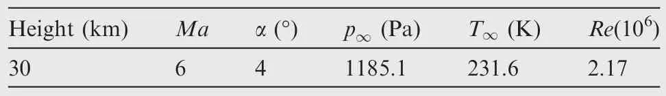
Table 2 HCV design point and freestream conditions.
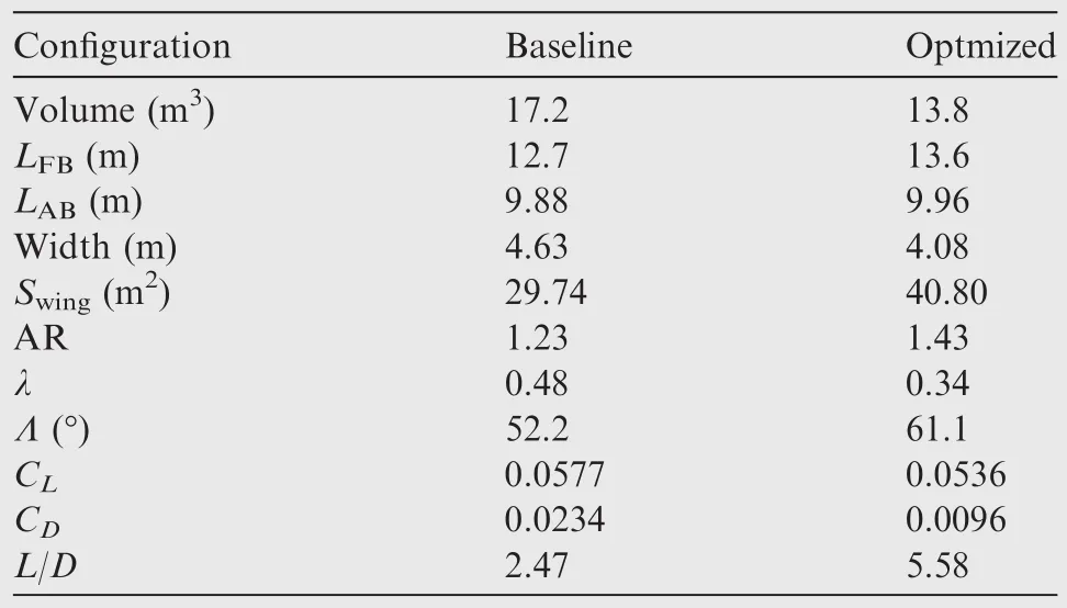
Table 3 Parameters comparison between baseline and optimized clean configurations.
In general,the optimized configuration becomes more slender than the baseline aircraft,which is beneficial to improve the high-speed aerodynamic performance.Obviously,a growth of slenderness is bad for the volume,so the volume of the optimized configuration is decreased by 19%compared with that of the baseline aircraft.Despite of the volume decrease,the cross section of the forebody becomes more regular than that of the baseline configuration,which is good for an increase of the space utilization ratio as well as a reduction of the assemble difficulty.Hence,the actual decrease of the volume index is not very large and the volume index of the optimized configuration fulfills the conventional requirement for a hypersonic cruise vehicle.It can also be observed that there are many differences between the optimized and baseline configurations.That the components of the configuration could vary so much is beneficial from the huge varying scope provided by the patched CST method.At the same time,the configuration integrity is not destroyed by the component shape variation,where the patched CST method makes contributions again.Considering all above,the design optimization of a clean configuration is successful,which can be judged by a significant aerodynamic performance improvement of the optimized configuration.The patched CST method proposed in this paper is efficient and suitable for modelling the complex configuration of a hypersonic cruise vehicle.
3.Design of inward-turning inlet basic flow
The design process of an inward-turning inlet can be divided into three main steps.The first step is generating the basic flow.The second step is specifying the lip or throat shape to create the inlet inviscid surface with the help of a streamline tracing technique.The last step is the boundary layer correction and the installation of an isolator.Several researchers25,26point out that an inward-turning inlet inherits the main characteristics of the basic flow.Therefore,the properties of the basic flow dominate the performance of the inward-turning inlet,so the basic flow determination should be well manipulated.
The evaluation criterion of the basic flow is more complex than that of the clean configuration,so a single objective is not enough while a multi-objective system is necessary.For comprehensively estimating the performance of the basic flow,the design targets should be derived from the following aspects:(A)gas compression efficiency;and(B)flow uniformity to the engine(scramjet).There is no doubt that the prior function of the inlet is compressing gas with a less total pressure loss as possible as it can.On the other hand,the flow uniformity cannot be ignored for the reason that a highly disordered flow has a huge negative effect on the combustion stability or even makes the engine fail.Above all,minimizing the total pressure loss factor σ'and the flow non-uniformity are the two core design targets.In this paper,the mass flow weighted variance of the Mach number behind the reflected shock D(Ma)is defined as the index of the flow uniformity,and its specific style is
whereis the mass flow of each cell,andthe total mass flow.
We have proposed a method to optimize the design of basic flow with targets of minimizing the total pressure lose factor and flow non-uniformity in Ref.27.As an essential part of the integrated configuration design method,the design method and result of the basic flow are necessary to be introduced briefly in this paper.In the method,the basic flow is solved by method of characteristic(MOC),and the computation process is simplified by the special flow property of normal shock wave reflection.Since the MOC needs an initial flow prior to the rest calculations,a quasi-ICFA28initial flow field is generated by solving Tayler-Maccoll equations,which makes the basic flow calculation more close to the reality than that derived from the oblique shock wave relationship.As we use a 2D non-uniform rational B-splines(NURBS)29curve to represent the generatrix of the basic flow,the design of basic flow is optimized by a GA-based system to change the generatrix shape.The Pareto theory30is also added in the optimization for solving the multi-object problem.
A basic flow inside a cone shaped by a straight generatrix is de fined as the original one and then we run the optimization system to improve the performance of basic flow under the same design condition with the clean con figuration.The total pressure loss of the original basic flow is as high as 11.3%and its flow non-uniformity is 3.7%.Compared with those of the original,the flow non-uniformity of the optimized basic flow(OBF)is decreased to 1.55%,and the total pressure loss is just 7.06%.The detail information of basic flow is listed in Table 4,where ηKEis the kinetic energy efficiency andisMa*at the outlet of the basic flow.CR is short for the contraction ratio.The gas compression process along the flow path represented by the pressure contours is shown in Fig.4.Fig.5 shows the comparison of the 1st order derivatives of the basic flow generatrixs.
The comparisons between the original basic flow and OBF can deliver much information as follows.The compression velocity along the flow path of the original basic flow is almost fixed,while that of the OBF varies significantly.The original basic flow compresses the air quickly in the very beginning with the help of a high-strength incident shock wave.On the contrary,the OBF slows down the compression velocity in the upstream area via increasing the 1st derivative of the generatrix,which is able to weaken the strength of the incident shock wave to decrease the total pressure loss.It must be pointed out that a relatively weak incident shock wave means a lower compression ratio in the upstream area,and thus the pressure of OBF in the upstream area is smaller than that of the original.For remedying the loss of gas compression in the upstream area,OBF decrease the 1st order derivatives rapidly to accelerate the gas compression processes in the middle section.In the downstream area,the OBF begin to increase its 1st order derivative again.This characteristic of OBF is good for fairing flow that ensures a relatively uniform flow behind the reflected shock wave to improve the flow uniformity.The Mach number distribution profile in Ref.27also illustrates that the Mach number distributions of OBF varies in a relatively smaller scope than the original,and the OBF even provides a flow field with a rare Mach number variation in the middle section.
Generally speaking,the OBF is favorable for improving the inlet work performance since it has a better overall performance.Especially the high level of flow uniformity provided by the OBF,it can overcome the negative sheering effect partially that provides a steadier working environment for the engine.Considering further design of the inward-turning inlet,the lip shape may be irregular in order to match the forebody.Therefore,a larger area of unified-flow provided by the OBF gives much flexibility to specify the lip shape,and the inlet determined by the lip shape is better to inherit the good char-acteristics of the basic flow.On the other hand,an irregular lip shape may lead to an irregular exit shape simultaneously,which is difficult to be compatible with the engine.For addressing this issue,a shape transition is likely to be employed during the design process of the isolator.The shape transition changes the previous smooth inlet surface and has a negative influence on the flow uniformity.Since the OBF is good enough,such a negative influence would be alleviated partially and the variation of flow uniformity would be more controllable.
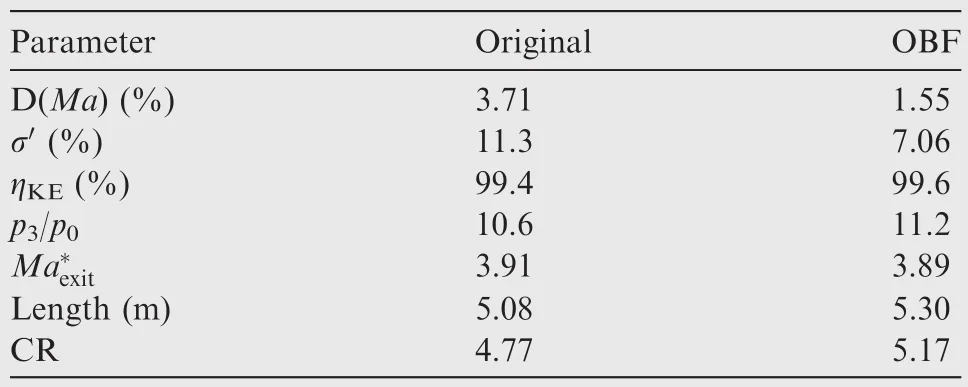
Table 4 Properties of original and optimized basic flows.
4.Integrated configuration design
4.1.Principle and method of lip shape generation
Projecting the inlet flat lip shape to the incident shock wave surface of the basic flow along the symmetric axis can specify the starting points of streamline tracing.The envelope of all the streamlines traced from these starting points is the inviscid shape of the inlet.Obviously,the lip shape dominates the actual shape of the inward-turning inlet.While considering the airframe and inlet integration,the design of the lip shape should be manipulated carefully.
Firstly,we give the inlet flat lip shape design result(shown in Fig.6),which is convenient for illustrating the principle and method of the inlet lip shape generation.In this paper,the flat lip shape is represented by cloud dots and a type of inclined droplet-like shape is used.From pointAto pointB,the forepart is a straight line and its slope is similar to that of the outline of the clean configuration forebody.This treatment is to avoid a large inflection angle between the inlet lip and the forebody outline,which guarantees the smoothness of the forebody upper surface.The rear part of theABsegment is like a circle whose polar radiusris decreased gradually with an increase of the polar angle φ.The reason whyrdecreases continuously fromAtoBis to make sure that the actual upper lip shape keeps monotonously decreasing along thexcoordinate,and thus the inlet determined by this lip shape will have no inflection angle and avoid the drag increase induced by this unsmooth configuration.As for theBCsegment,the generation method includes two steps.The first step is generating several temporary points whoseris decreased simultaneously with φ.This type of design principle is also for generating a smooth inlet configuration,which impairs the negative influence of the inlet on the overall performance via a better integration with the airframe.Here,the variation law ofrwith φ is specified by the style of arithmetic sequence.The curve linked by these temporary points is internally concave.For capturing much more air,the lip shape should be externally convex,and hence the actual lip is a mirror image of these temporary points based on lineBC.Similarly,theCAsegment can be created except that the variation law ofrwith φ is reversed.
Despite that the principle and method of the lip shape generation are given in the above paragraph,there are still some parameters that need to be defined,such as the positions of pointsAandB.In this paper,φAis 47°andrAis 1 m,while φBandrBare 140°and 0.68 m,respectively.In reality,the lip shape is highly related to the air capture ratio,which is greatly influenced by the weight of payload and the fuel type.Therefore,the air capture ratio is difficult to be defined,and thus the lip shape presented here is just a reasonable assumption that the inlet is able to capture enough air for a conventional scramjet engine to balance the drag at the design point.For the reason that the proposed modelling method can give much flexibility to the integration configuration design,it is easy to adjust a larger or smaller inlet in order to fulfill the air mass flow capture demands.Only the lip shape design process followed the principle proposed above,the choices of these parameters could be flexible until a determination of the inlet with good performance.Furthermore,a lip shape design optimization may be put into use when instructed by the principle and method proposed in this paper,which leads to an inlet performance improvement as well as a better integration with the airframe.
The flat lip shape is projected to the incident shock wave surface of the basic flow,and then the inlet inviscid surface is created with the help of streamline tracing technique.For the inviscid inlet surface,a boundary layer correction is needed to make the inlet accustom the viscous environment.The boundary layer correction method proposed in Ref.31is used in this paper,and the specific correction value is half of the displacement thickness of the local boundary layer.Installation of the isolator is the last step to generate the complete inlet.Empirically,the length of the isolator is 8 times longer than the diameter of the throat.If the cross section of the isolator is kept the same with the inlet throat,it would be difficult to be integrated with the engine.Considering that,a shape transition of the cross section is used to design the isolator.The first half of the isolator is linearly blended by the throat shape and a similar ellipse,and the last 50%is kept as a constant section.The complete inlet is shown in Fig.7.
4.2.Forebody/inlet integration
4.2.1.Cut of clean configuration
Inlets are arranged laterally in the HCV configuration designed in this paper.However,the clean configuration doesn’t reserve any place for inlets,and thus cutting the clean configuration is inevitable.The forebody of the clean configuration is cut via a plane parallel to thexOzplane through a specific cutting point.The cutting point is on the outline of the forebody and determined by its proportion to the length of the forebody.Fig.8 shows a 30%cutting result.
4.2.2.Inlet installation
The installation of the inward-turning inlets is relatively easy via simple geometric translations and rotations.Firstly,move an inlet to a position where pointAin Fig.7 and pointA'in Fig.8 become a superposition point pair.Secondly,rotate the inlet by a specific angle along the axis which is parallel to theyaxis and through pointA.The incomplete configuration but with inlets is shown in Fig.9.
4.2.3.Forebody surface regeneration
The forebody surface regeneration includes two steps.The first step is to generate two outlines for further surface construction.The first one is the common outline of the upper and lower surfaces,which is similar to that of the clean configuration and parametrically represented by the CST method.The other one is a connection curve between pointCin Fig.7 and its projection pointC'on the front edge of the lower face of the aft body along thexdirection.This curve is named as the assistant outline and generated by a cubic polynomial interpolation that is easy to impose derivative conditions at the starting and ending points.The reason for generating this assistant outline is that the rebuilt surface of the lower face of the forebody is divided into two parts,and each part cannot be established until all the outlines are specified.All the outlines used to regenerate the forebody surfaces are shown in Fig.10.
The second step is to build the forebody surfaces with the help of the COONs surface generation method.29The COONs method is developed based on NURBS curves and surfaces.Ref.29gives its detailed derivation process and thus we don’t repeat it again.Briefly,the COONs method can parametrically construct a 3D surface with specific boundaries and 1st derivative vectors at the boundaries.The number of boundary curves must be four and all the boundary curves should be expressed by NURBS curves.As for the forebody surfaces regeneration,it is also acceptable to directly use NURBS surfaces instead of the COONs method.Compared with the COONs method,the NURBS method needs numerous complex treatments that involve specifying the positions of control points,and smooth connections across the interface are difficult to be guaranteed.On the contrary,the regeneration process is simplified by the means of the boundary-orient surface generation method,and a complex control-point search can be omitted instead of a simple outline generation.What’s important,smoothness across the adjacent surface is guaranteed via imposing derivative conditions.
In this paper,the transformation between the CST and NURBS methods is easy and precise via the NURBS curve fitting.There are two approaches to calculate the 1st derivative vectors at the boundaries.The first one is to compute the numerical difference approximately instead of the actual derivative.This method is suitable for the boundary outline of a given surface,such as the remaining surfaces of the forebody.Another one is to give a constant value.For the freedom boundary,such as the lip of the inlet,we set the derivative vector as 0.For the assistant outline,its derivative vector is[0,1,0]or[0,-1,0]varying with different surfaces.After regenerating the surface,the configuration with inlets is shown in Fig.11.Hereto,all the design stages of this HCV configuration with inward-turning inlets are finished.Fig.12 is the final design result and the whole process is summarized in Fig.13.
5.Flow field and performance analysis
5.1.Numerical simulation:methods and conditions
As the HCV configuration has been generated,a performance estimation is just around corner to testify if the design result is good or not.The performance information is obtained from the flow field over the configuration via numerical simulations.In this paper,the commercial software ANSYS Fluent is used to simulate the flow field.In the numerical simulations,the Navier-Stokes equations are solved with a 2nd order Roe scheme,and an RNGk-ε turbulence model as well as a standard wall function are used to obtain the viscous information.During the simulation process,a calorically perfect gas condition is imposed and the viscosity of the fluid is specified by the Sutherland laws.At the far field,the freestream condition is applied and the outlet condition is specified by extrapolation.Besides,adiabatic and no-slip conditions are applied to the wall area.A hexahedron-based unstructured mesh is used to discretize the computation field.Table 5 lists the freestream conditions varying with different Mach numbers for the following sections.
For estimating the numerical simulation accuracy of the methods and conditions employed in the current work,a model of space shuttle is chosen to complete the validation.Ref.32gives the shape of the testing model and the related aerodynamic information obtained by a wind tunnel experiment.In this case,the experimental conditions are set as follows:freestream MachnumberMa∞=8.04,freestream Reynolds numberRe∞=1.13×10⁷, total pressurept=7.8 MPa,and total temperatureTt=892 K.In the numerical simulations,the aerodynamic performances of the space shuttle are obtained with variations of the angle of attack α,ranging from-5°to 25°in increments of 5°.The force coefficient comparison between the numerical simulation results and the experimental data is shown in Fig.14(a).It is clear that the lift and drag coefficients from the numerical simulation results are in good agreements with the experimental data32under the hypersonic condition,especially at the points with smaller angels of attack.When the angle of attack is above 15°,the force coefficients obtained by numerical simulations are slightly over-predicted.Fortunately,this overprediction has marginal in fluence on the lift-to-drag ratio.Fig.14(b)illustrates the density gradient of numerical simulation results under the condition of α =10°,and the shock wave shape and position captured by the numerical simulations are similar to the shock wave schlieren image in the experimental data.32Besides,Refs.33,34also employed validation on this software with similar methods and conditions.Their results as well as the above information prove that the numerical methods used in this study are able to simulate the hypersonic flow field within acceptable error margins,and the numerical results presented in the subsequent sections are believable.
5.2.Analysis of flow field characteristics
Fig.15 shows the Mach number slice contours along the vehicle center axis at a condition of freestreamMa∞=6 and 0°angle of attack.It can be vividly observed that almost all the parts of the vehicle are embodied by the shock wave induced by the forebody,which is similar to the special characteristic of a waverider.Especially,the relatively higher pressure gas behind the shock wave is almost all limited in the area specified by the envelope of the shock wave on the lower face of the vehicle,which makes a great contribution to the lift.On the other hand,a relatively small angle between the upper and lower surfaces at the leading edge is also favorable to reduce the strength of the shock wave,and thus the shock wave drag can be reduced consequently.Even more,the shock wave induced by the lip of the inlet as well as the shock wave induced by the body of the vehicle are well blended,which gives a much positive effect on the performance of the vehicle.Firstly,there is no complicated shock wave interaction and reflection just in front of the fore body,and hence an extra drag does not come into appearance.Secondly,the good shock wave match guarantees that the flow quality remains good ahead of the inlet,and thus the actual flow field of the inlet is similar to the basic flow,which provides a stable working environment for the engine.
The Mach number contours at the positions of the throat and isolator exit are displayed in Fig.16.At the position of the throat,the Mach number keeps almost constant except the area near the convex corners.Obviously,the sharp corners do worse in keeping the flow uniform.Besides,the flow uniformity at the position of the isolator exit also seems good although the shape of the isolator cross section has gradually changed as well as the boundary layer has greatly developed.This desirable phenomenon turns out that the forebody shock wave does not destroy the flow quality ahead of the inlet and the preconceived flow field has been achieved.Two factors make contributions to this situation.The first one is that the layout of the con figuration impairs the interaction between inlets and the forebody,and the smooth modelling of the configuration assures this advantage.Moreover,the inwardturning inlet is determined by the dual-in flection-point basic flow.Despite of the irregular lip shape and the shape transition in the isolator,the inlet still has a relatively large area of unified-flow via inheriting the good properties provided by the dual-inflection-point basic flow.All the above turns out that the inlet design method proposed in this paper is still in effect after the inlet being integrated with the vehicle.The advantages of the wing-body configuration are assured by the usage of the design method proposed in the paper.
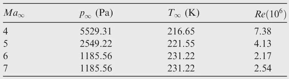
Table 5 Freestream conditions for numerical simulations.
Fig.17 shows the pie charts of the lift and drag derived from each vehicle component.In the total drag statistics of this study,the drag of the inlet and isolator is taken into account,while the drag of the engine cowl and nozzle as well as the base drag of the vehicle are excluded.The pie charts show that the body and wing make most contributions to the lift and drag,especially for the body which accounts for over 70%.Generally speaking,the body and wing have positive influences on the aerodynamic performance.However,for the inlet,it only contributes about 1%of the total lift but accounts for 10%of the drag.It can be easily explained that the installation of the inlet destroys the integrity of the clean configuration,so the irregular configuration always leads to an extra drag.On the other hand,the inlet has dramatically increased the windward and wet areas;therefore the pressure drag and friction drag are increased consequently.All the above tells that the inlet has a great negative influence on the aerodynamic performance,and hence its design and the integration with the vehicle must be manipulated carefully.
5.3.Analysis of aerodynamic characteristics
5.3.1.Influence offreestream velocity
For estimating the influence of the freestream velocity on the aerodynamic characteristics of the HCV,numerical simulations are processed on the condition of freestreamMa∞=4–7 at 0°angle of attack.In the following paper,subscript ‘t” represents the variables at the position of the inlet throat,whereas subscript ‘e” represents the variables at the position of the isolator exit.
Fig.18 shows the variations of the inlet compression ratio and the total pressure recovery factor σ with the freestream Mach number.As the freestream Mach number varies from low to high,the strength of the shock wave is increased continuously,so the compression ratio grows gradually whereas the total pressure recovery decreases consequently.Besides,for the reason that there are more complex shock wave reflection and interaction,the compression ratio rises much more in the isolator than that in the throat.On the other hand,the total pressure recovery loses much more in the isolator.
The variation of the inlet mass capture ratio φ with the freestream Mach number is shown in Fig.19.It can be obviously observed that the mass capture ratio is increased simultaneously with the freestream Mach number varying from 4 to 7.This phenomenon can be turned out as follows.As the Mach number goes higher and higher,the incident shock wave moves towards the lip of the inlet and its actual flow field becomes similar to the presupposed basic flow.Hence,the overflow window shuts down gradually,which results in an increase of the mass capture ratio.On the other hand,the boundary layer becomes thicker and thicker as the freestream Mach number varying from low to high.Therefore,the congestion led by the development of the boundary layer hinders the continuous increase of the mass capture ratio,which can be testified by the deceleration of the mass capture ratio increase.
Fig.20 displays the variations of the lift coefficientCLand the drag coefficientCD(including pressure dragCD,preand viscous dragCD,vis)with the freestream Mach number.This graph shows thatCLis significantly decreased,which is mainly resulted from an increase of the flight height.CDhardly varies with the variation of the Mach number but its components change a lot.As the HVC flies higher and higher,the local static pressure becomes smaller and smaller,which makes a decrease of the pressure drag.On the other hand,the viscous drag dominates more and more due to the development of the boundary layer.In general,the lift-to-drag ratio is much larger than zero at 0°angle of attack,which means that the HCV has high cruise efficiency under these conditions,especially on the low-hypersonic conditions.This good characteristic is helpful to achieve a low-speed release or even taking off from the land.High cruise efficiency also proves that the configuration design is successful.
5.3.2.Influence of angle of attack
Varying the angle of attack from-4°to 6°on the condition offreestreamMa∞=6 can be used to analyze the performance of the HCV influenced by the angle of attack.Fig.21 shows the variations of the inlet compression ratio and the total pressure recovery factor σ with the angle of attack.As the angle of attack varies from negative to positive,the compression ratio increases continuously due to the movement of the shock wave.As it is known to all,the actual flow deflection angle is the sum of the leading compression angle and the angle of attack.In this process,the actual flow deflection angel becomes larger and larger,which leads to an increase of the strength of the shock wave.The variation of the strength is in charge of the increase of the compression ratio as well as the total pressure lose.As the angle of attack varying from-4°to 0°,the total pressure just has a minor variation.On these conditions,the incident shock wave is far away from the leading edge of the inlet,where the incident shock wave has a minor effect on the internal flows.Therefore,the total pressure loss remains almost constant.Once the angle of attack varying from 0°to 6°,the situation is changed.Under these conditions,the incident shock wave is more closely to the inlet,or even swallowed into the inlet,where the incident shock wave has much more effect on the internal flows via inducing shock wave reflections and interactions.Therefore,the pressure and total pressure loss are increased significantly.
The trend of the inlet mass capture ratio varying with the angle of attack is shown in Fig.22.The inlet mass capture ratio is increased continuously with the variation of the angle of attack.As the angle of attack increases,the windward area of the inlet becomes larger and larger.At the same time,the shock wave moves towards the inlet lip or even is swallowed into the inlet,which leads to a close of the overflow window.Both of these two reasons make the inlet mass capture ratio increase with the variation of the angle of attack.
Fig.23 shows the lift and drag coefficients varying with the angle of attack.As for the drag,the pressure drag is increased significantly with the variation of the angle of attack whereas the viscous drag almost keeps constant.The increases of the actual windward area and the strength of the shock wave both make contributions to an increase of the pressure drag.On the other hand,the development of the boundary layer as well as the wet area are not sensitive to the variation of the angle of attack,and hence the friction drag hardly varies with the variation of the angle of attack.As the pressure drag dominates more and more in the total drag,the total drag is increased with the variation of the angle of attack.Besides,the lift is always increased with the angle of attack varying from negative to positive.
At the design point,the lift-to-drag ratio of the configuration is as high as 5.2 and the inlet works well with a high flow capture ratio,a high compression ratio,and high flow uniformity,which can be judged from the above analysis.Although the lift-to-drag ratio is lower than that of the clean configuration due to the installation of the inlet,it retains at a high level compared with those of other conventional configurations.For the reason that the integration design has been carefully manipulated with the help of the patched CST modelling method and the dual-inflection-point basic flow,the negative influence of the inlet on the overall aerodynamic performance is limited,and the inlet is well integrated with the airframe as well.Generally speaking,all the design targets are fulfilled by the configuration design results,which reflects that the design method proposed in this paper is practical and efficient.
6.Conclusions
(1)A novel geometric parametrically modelling method based on a combination of patched CST and COONs surface is proposed.The method is suitable for parametrically modelling a complex wing-body aerodynamic configuration with inward-turning inlets,especially those with irregular lip shapes.The method enlarges the design space of components on the premise of guaranteeing the configuration integrity via special constraints imposed on the interface across adjacent surfaces,and this property is favorable for an optimization system to search the optimal configuration in a larger geometric varying scope.
(2)Defining the mass flow weighted variance of the Mach number as the flow uniformity index,a multi-objective optimization system is used to design the basic flow with improvements of compression efficiency and flow uniformity.The basic flow design result,a basic flow inside a cone shaped by a dual-inflection-point generatrix,improves both the compression performance and the flow uniformity by about 50%compared with the straight generatrix basic flow.Related analysis delivers that the mechanism of this type of basic flow is the compression velocity variation induced by the variation of the generatrix slope along the flow path.
(3)A design principle is proposed to instruct the inlet lip shape determination in order to make the inlet be well integrated with the airframe.Instructed by the principle,an inward-turning inlet is generated by streamline tracing in the optimized basic flow,while a treatment of shape transition is imposed on the isolator for a convenient inlet/engine integration.
(4)Numerical simulations show that the HCV configuration designed in this paper has an excellent flow structure and aerodynamic performances.At the design point,the lift-to-drag ratio reaches as high as 5.2 and the inlet works well with a high level of compression performance and flow uniformity,which proves that this configuration can suppress the negative influence of the installation of the inlet on the overall performance.The well designed inward-turning inlet,the clean configuration with good performance,the smooth geometric modelling,as well as the reasonable configuration layout,which are all determined by the method proposed in this paper,are the key factors to the integration configuration design.The success of the design indicates that the integration method proposed in this paper is efficient and practical,and the major design concern of balancing the aerodynamic performance against the requirements for efficient propulsion is well addressed.
Acknowledgements
This work was supported by the ‘111” Project of China(No.B17037).The authors are also grateful to the reviewers for their extremely constructive comments.
1.Bertin JJ,Cummings RM.Fifty years of hypersonics:where we’ve been,wherewe’regoing.Prog.AerospaceSci.2003;39(6–7):511–36.
2.Cai GB,Xu DJ.Hypersonic aircraft technology.Beijing:Science Press;2012.p.3–14[Chinese].
3.Lewis MJ.A hypersonic propulsion airframe integration overview.Reston(VA):AIAA;2003.Report No.:AIAA-2003-4405.
4.Pittman J,Bartolotta PA,Mansour NN.Fundamental aeronautics hypersonics project reference document.Washington,D.C.:NASA;2006.Report No.:20060028873.
5.Liu J,Ding F,Huang W,Jin L.Novel approach for designing a hypersonic gliding–cruising dual waverider vehicle.Acta Astron2014;102:81–8.
6.He XZ,Zhou Z,Qin S,Wei F,Le JL.Design and experimental study of a practical osculating inward cone waverider inlet.Chin J Aeronaut2016;29(6):1582–90.
7.You YC,Zhu CX,Guo JL.Dual waverider concept for the integration of hypersonic inward-turning inlet and airframe forebody.Reston(VA):AIAA;2009.Report No.:AIAA-2009-7421.
8.Li YZ,Zhang KY.Integrated design offorebody and inlet based on external and internal conical basic flow field with controlled Mach number distribution surface.Acta Aeronaut Astronaut Sin2015;36(1):289–301[Chinese].
9.Engelund WC,Holland SD,Cockrell CE,Bittner RD.Aerodynamic database development for the Hyper-X airframe integrated scramjet propulsion experiments.J Spacecraft Rock2001;38(6):803–10.
10.Hank JM,Murphy JS,Mutzman RC.The X-51A scramjet engine fl ight demonstration program.Reston(VA):AIAA;2008.Report No.:AIAA-2008-2540.
11.Chris SG,Robert JV,Robert P.Low speed flight testing of an X-43A hypersonic lifting body configuration12th AIAA international space planes and hypersonic systems and technologies.Reston(VA):AIAA;2003.
12.Li HF,Lin P,Xu DJ.Control-oriented modeling for air-breathing hypersonic vehicle using parameterized configuration approach.Chin J Aeronaut2011;24(1):81–9.
13.Che J,Tang S.Integrated optimization design of hypersonic cruise vehicle.Reston(VA):AIAA;2008.Report No.:AIAA-2008-0142.
14.Defoort S,Ferrier M,Serre L,Pastre JL,Paridaens C,Scherrer D,et al.LAPCAT II:Conceptual design of a Mach 8 TBCC civil aircraft,enforced by full Navier-Stokes 3D nose-to-tail computation.Reston(VA):AIAA;2011.Report No.:AIAA-2011-2317.
15.Van Wie DM.Scramjet inlets.In:Curran ET,Murthy SNB,editors.Scramjetpropulsion.Reston(VA):AIAA;2000.p.447–511.
16.Moelder S,Szpiro EJ.Busemann inlet for hypersonic speeds.J Spacecraft Rock1966;3(8):1303–4.
17.Smart MK.Design of three-dimensional hypersonic inlets with rectangular-to-elliptical shape transition.J Propulsion Power1999;15(3):408–16.
18.You YC,Liang DW.Design concept of three-dimensional section controllable internal waverider hypersonic inlet.Sci China Series E:Technol Scinces2009;52(7):2017–28.
19.Nan XJ,Zhang KY,Jin ZG.Integrated design of waverider forebody and lateral hypersonic inward turning inlets.Acta Aeronaut Astronaut Sinica2012;33(8):1417–26[Chinese].
20.Walker SH,Rodgers F.Falcon hypersonic technology overview.Reston(VA):AIAA;2005.Report No.AIAA-2005-3253.
21.Pezzella G,Marini M,Cicala M,Vitale A,Langener T,Steelant J.Aerodynamic characterization of HEXAFLY scramjet propelled hypersonicvehicle.Reston(VA):AIAA;2014.ReportNo.:AIAA-2014-2844.
22.Kulfan BM.Recent extensions and applications of the‘CST”universal parametric geometry representation method.Reston(VA):AIAA;2007.Report No.:AIAA-2007-7709.
23.Liu CZ,Duan YH,Cai JS,Yang GD.Applications of multi-block CST method for quasi-waverider design.Reston(VA):AIAA;2014.Report No.:AIAA-2014-0189.
24.Spalding DB,Chi SW.The drag of a compressible turbulent boundary layer on a smooth flat plate with and without heat transfer.J Fluid Mech1964;18(1):117–43.
25.You YC.An overview of the advantages and concerns of hypersonic inward turning inlets.Reston(VA):AIAA;2011.Report No.:AIAA-2011-2269.
26.Billig FS,Baurle RA,Tam CJ,Stephen W.Design and analysis of streamline traced hypersonic inlets.Reston(VA):AIAA;1999.Report No.:AIAA-1999-4974.
27.Wang JF,Cai JS,Duan YH.Multistage optimization design method of hypersonic inward turning inlet.Acta Aeronaut Astronaut Sin2015;36(12):3759–73[Chinese].
28.Mo¨lder S.Internal,axisymmetric,conical flow.AIAA J1967;5(7):1252–5.
29.Piegl L,Tiller W.The NURBS book.2nd.New York:Springer;1997.p.60–73.
30.Wang XP,Cao LM.Genetic algorithm:theory,applications and software.Xi’an:Xi’an Jiaotong University Press;2002.p.23–31[Chinese].
31.Drayna TW,Nompelis I,Candler GV.Hypersonic inward turning inlets:Design and optimization.Reston(VA):AIAA;2006.Report No.:AIAA-2006-297.
32.Li SX.The flow characteristics for the typical model in hypersonic fl ows.Beijing:National Defense Industry Press;2007.p.181–5[Chinese].
33.Ding F,Liu J,Shen CB,Huang W.Novel inlet-airframe integration methodology for hypersonic waverider vehicles.Acta Astronaut2015;111:178–97.
34.Wang CP,Tian X,Yan LF,Xue LS,Cheng KM.Preliminary integrated design of hypersonic vehicle configurations including inward-turning inlets.J Aerospace Eng2015;28(6):04014143.
2 August 2016;revised 21 November 2016;accepted 7 December 2016
Available online 14 June 2017
*Corresponding author.
E-mail address:caijsh@nwpu.edu.cn(J.CAI).
Peer review under responsibility of Editorial Committee of CJA.
Production and hosting by Elsevier
http://dx.doi.org/10.1016/j.cja.2017.05.002
1000-9361©2017 Production and hosting by Elsevier Ltd.on behalf of Chinese Society of Aeronautics and Astronautics.
This is an open access article under the CC BY-NC-ND license(http://creativecommons.org/licenses/by-nc-nd/4.0/).
Aerodynamic configurations;
Hypersonic;
Integration design;
Inward-turning inlet;
Numerical simulation
杂志排行

CHINESE JOURNAL OF AERONAUTICS的其它文章
- Wake structure and similar behavior of wake profiles downstream of a plunging airfoil
- Self-sustained oscillation for compressible cylindrical cavity flows
- Numerical studies of static aeroelastic effects on grid fin aerodynamic performances
- A new vortex sheet model for simulating aircraft wake vortex evolution
- Linear stability analysis of interactions between mixing layer and boundary layer flows
- Aerodynamic multi-objective integrated optimization based on principal component analysis