Trajectory reshaping based guidance with impact time and angle constraints
2016-11-24ZhaoYaoShengYongzhiLiuXiangdong
Zhao Yao,Sheng Yongzhi,Liu Xiangdong
School of Automation,Beijing Institute of Technology,Beijing 100081,China
Key Laboratory for Intelligent Control and Decision of Complex Systems,Beijing Institute of Technology,Beijing 100081,China
Trajectory reshaping based guidance with impact time and angle constraints
Zhao Yao,Sheng Yongzhi*,Liu Xiangdong
School of Automation,Beijing Institute of Technology,Beijing 100081,China
Key Laboratory for Intelligent Control and Decision of Complex Systems,Beijing Institute of Technology,Beijing 100081,China
This study presents a novel impact time and angle constrained guidance law for homing missiles.The guidance law is first developed with the prior-assumption of a stationary target,which is followed by the practical extension to a maneuvering target scenario.To derive the closed- form guidance law,the trajectory reshaping technique is utilized and it results in defining a specific polynomial function with two unknown coefficients.These coefficients are determined to satisfy the impact time and angle constraints as well as the zero miss distance.Furthermore,the proposed guidance law has three additional guidance gains as design parameters which make it possible to adjust the guided trajectory according to the operational conditions and missile’s capability.Numerical simulations are presented to validate the effectiveness of the proposed guidance law.
1.Introduction
A major objective of terminal guidance is to achieve a minimum miss distance.1,2Current guidance applications,however,also require to impose additional terminal constraints like impact angle and impact time to improve the guidance performance.In order to enhance the effectiveness of the warhead,a particular terminal impact angle should be specified.By comparison,the impact time constraint is imposed to achieve a salvo attack or a cooperative attack for homing missiles,which can greatly enhance the survivability of the missile against advanced defense systems.Due to these important reasons,the guidance laws with multiple terminal constraints have been extensively studied in the past few decades.
Since the concept of impact angle guidance was initially reported in 1973,3a large amount of work has been per formed towards solving this problem.As a typical work in this area,modified proportional navigation guidance(PNG)laws were investigated to fulfill the impact angle constraints.4–8Except for the modified PNG,some other control methods,such as optimal control,9–11suboptimal control12–14and sliding mode control(SMC),15–18have also been utilized to derive the impact angle constrained guidance laws.Compared with the impact angle control laws,the studies on the impact time control guidance law are relatively rare.19–22
The guidance scheme proposed in Ref.23initiated the research area where both impact angle and impact time are constrained.From then on,there have been some valuable contributions made in this field.24–27Through a combination of line-of -sight(LOS)rate shaping process and a secondorder SMC approach,an impact time and angle(ITA)guidance law was developed in Ref.24for engaging a modern warfare ship.A closed- form ITA guidance law was presented in Ref.25,where a feedback term was added to a specially constructed biased PNG to satisfy the ITA constraints.In Ref.26,an optimal ITA guidance scheme for the nonlinear missile model was derived,which not only ensured the ITA requirements but achieved the minimum integral square control efforts as well.Based on the polynomial guidance law analyzed in Refs.28,29,an augmented polynomial guidance law was devised in Ref.27to solve the ITA guidance problem.With the proper selection of the guidance gains,the generated homing trajectory turned out to be quite similar to the optimal solution.
In this paper,a new closed- form ITA guidance law is developed for homing missiles.The focus is first placed on engaging a stationary target.To derive the proposed guidance law,a trajectory reshaping process is introduced.This process results in defining a specific polynomial function with two unknown coefficients.One is tuned to adjust the length of the homing trajectory so as to achieve the impact time requirement.The other is determined to make the polynomial function equal to zero at each time step,so that the terminal impact angle constraint as well as the zero miss distance can be satisfied.Using the obtained solutions of the two coefficients,the guidance command can be expressed as a combination of an impact angle control law and a bias term,which is incorporated to annul the impact time error.After well developed,the guidance law is further extended to deal with maneuvering targets using the notion of predicted interception point(PIP).The associated modification in the guidance command with respect to a maneuvering target is also illustrated.
With respect to the previously published ITA guidance methods,the proposed guidance scheme could provide several advantages in the following aspects.Firstly,the approach developed in Ref.24requires an optimization routine to generate feasible LOS angle and rate profiles that meet the impact time and angle constraints,whereas such process is not needed in the implementation of the proposed ITA guidance law.Secondly,as long as the engagement conditions are determined,the guidance laws in Refs.23,25would result in certain homing trajectories.The proposed law,however,has three guidance gains as design parameters which can be utilized to shape the homing trajectory and command profile in accordance with the missile’s capability.In particular,the guided trajectories could exhibit similar behavior to the energy optimal solutions by choosing proper guidance gains for a given engagement.Although the numerical guidance strategy investigated in Ref.26could minimize the integral square control efforts,it requires to solve the two point boundary value problem on line and additional computational burdens would be imposed on the missile-borne computer.So its practical application is limited.Thirdly,while the works in Refs.23,25–27just focused on stationary targets,this work also lays emphasis on engaging targets that are maneuvering.
2.System model and problem formulation
Consider a planar homing engagement between the missile M and the target T as depicted in Fig.1.The missile is assumed to be traveling at a constant velocity V and the target is assumed to be stationary.The positions of the missile and the target in the inertial X–Y coordinate are denoted as(x,y)and(xf,yf),respectively.The missile’s heading angle is represented by θ.The acceleration command u is applied normal to the missile’s velocity vector.
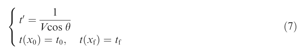
The equations of motion for the homing engagement are given as9
where t0and tfare the initial launch time and the designated impact time,respectively;θfis the desired impact angle.Note that the values of tfand θfare determined be fore the missile is launched.
The design goal of the ITA guidance law can be summarized as follows.It is equivalent to designing a controller u such that

It can be observed from Eqs.(1)–(3)that the equations of motion treat t as the independent variable.In terms of the homing guidance problem,however,the downrange x is a better choice for the independent variable due to the fact that xfalways corresponds to the target’s location while tfvaries with different selections of impact time.24Hence,with respect to the independent variable x,a new set of equations of motion can be derived as
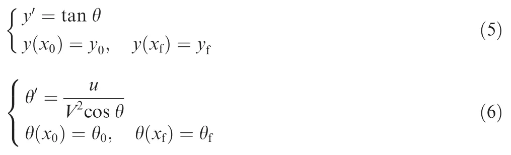
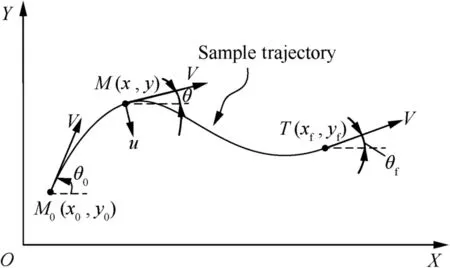
Fig.1 Engagement geometry.
If the X-axis is defined in a way that makes the desired impact angle θfequal to zero,as in the general impact angle control problems,the equations of motion,i.e.,Eqs.(5)and(6),can befurther trans formed to the following linearized form:19,23,27

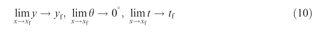
Correspondingly,the design goal can be equivalently described as follows:
3.Guidance law with only impact angle constraint
In this section,the statefeedback guidance law for engaging a stationary target with only impact angle constraint is derived.Be fore moving on,two variables are designed as follows:

From Eq.(11),it can be drawn that the miss distance will be minimized and the desired impact angle can be achieved as long as σ and σ′are both driven to zero as the downrange x goes to xf.There fore,the guidance law should be designed to drive both σ and σ′to zero as the missile approaches the target.
To devise the guidance law,a specific polynomial function is first defined as follows:

where xgo=xf-x;n,p,q,A and B are constants that need to be determined.
Assuming that ξ=0,one can get the following first-order linear differential equation:
By solving this equation,the analytic solution for σ can be obtained as
where C is a constant determined by the initial condition as follows:
where σ0and xgo0represent the initial values of σ and xgo.
Then,differentiating Eq.(14)with respect to x,we can obtain the analytic solution of σ′as
By inspecting Eqs.(14)and(16),it can be drawn that both σ and σ′will reach zero as x goes to xf(i.e.xgogoes to zero)as long as the conditions ξ=0,n>1,p>0,q>0,p≠n-1 and q≠n-1 hold.
For the sake of involving the impact time constraint into the guidance law design in the next section,the coefficients A and B need to be determined separately and thus p and q should not be equal to each other.Without loss of generality,the coefficients n,p and q are selected such that the condition q>p>n-1>0 holds.
Remark 1.The above analysis reveals that Eq.(13)essentially defines a reasonable homing trajectory for the missile;that is,as long as the system states satisfy Eq.(13),both σ and σ′would be driven to zero at x=xf,which guarantees a minimum miss distance as well as a zero impact angle error.Hence,the design goal of the impact angle control guidance law can be accordingly trans formed to maintaining ξ at zero during the entire homing phase.
To achieve this requirement at the initial time(i.e.,ξ=0 at x=x0),the conditionmust hold,from which the coefficient A can be determined as
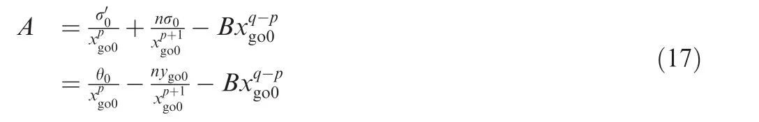
where ygo0represents the initial value of ygo.
Then,the guidance command should be derived to make ξ identically equal to zero during the remaining flight.Since the coefficient A has been tuned to meet ξ=0,the guidance command just needs to make ξ′equal to zero.Taking the derivative of Eq.(12)and letting it equal to zero yield

Associating this result with Eq.(9),we can obtain the guidance command as

Remark 2.From Eqs.(17)and(19),it can be observed that although the guidance command is expressed in a statefeedback form,the coefficient A is calculated using the initial system states.Because the linearized equations of motion,i.e.,Eqs.(8)and(9),are utilized in the guidance law design,large approximation errors may be produced in the initial homing phase,which would lead to terminal state errors.Further note that in practical implementation,the guidance command cannot be achieved immediately after its generation owing to the autopilot lag.In addition,the guidance command that the missile can generate is bounded according to the missile’s capability.These limitations may also cause large miss distance or violation of terminal constraints.To enhance the robustness of the guidance law,the coefficient A is suggested to be initialized and recalculated at each step of x as follows:

The aforementioned equation ensures that the condition ξ=0 holds at each step of x,which implies that the homing trajectory is reshaped continuously.
By substituting Eq.(20)into Eq.(19),the associated guidance command can be trans formed to thefollowing form:

It can be clearly seen from Eq.(21)that the guidance command consists of three components.The first component controls the missile to the collision course,thus enabling it to hit the target.The second component contributes to the achievement of the desired impact angle.The third component corresponds to a bias term that accounts for some other requirements,if needed.To further analyze the characteristics of the guidance command Eq.(21),the associated closed- form solutions for the system states will be derived in the following discussion.
Using Eqs.(9),(11)and(21),the following linear second order ordinary differential equation can be obtained:
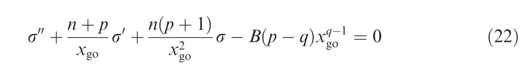
Solving Eq.(22)yields

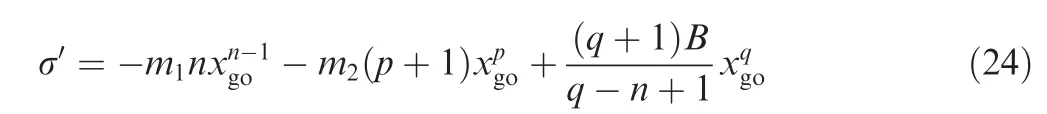
Then,taking the derivative of Eq.(23),we can obtain the solution for σ′as
The coefficients m1and m2in Eqs.(23)and(24)are both constants that are determined by the initial conditions as
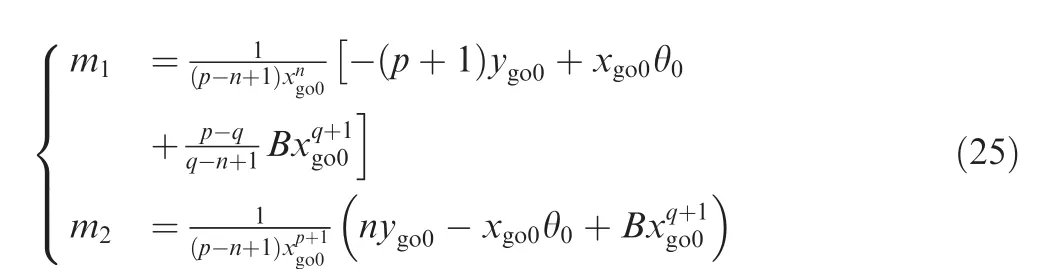
Hence,the closed- form solutions for the guidance system states can be obtained from Eqs.(11),(23)and(24)as

It can be drawn from these solutions that the terminal requirements are always satisfied even through the coefficient B is an arbitrary constant.This result reveals that in addition to the constraints on miss distance and impact angle,the guidance law Eq.(21)is able to provide an additional degree of freedom by B,which can be used to shape the homing trajectory to fulfill the impact time constraint.Note that in terms of the impact angle control guidance problem,the coefficient B can be simply set to zero,thus reducing the guidance law Eq.(21)to thefollowing simple form:

4.Guidance law with impact time and angle constraints
Based on the analysis in Section 3,the ITA guidance law will be derived in this section.Note that regardless of the selection of B,the missile can be steered to intercept the target along the desired impact angle by employing the guidance law Eq.(21).In the sequel,a proper value of B will befound to meet the impact time requirement.
Because the missile maintains a constant velocity,the impact time constraint can be equivalently achieved by adjusting the length of the homing trajectory.That is,the length of the predicted flight trajectory at the current time should be equal to the desired distance to go,i.e.,where

As suggested by Kim et al.29,the calculation of the length of the homing trajectory can be approximated as follows:

Note that the trajectory length Sgois calculated at each step of x,and the closed- form solution θ in Eq.(26)should be trans formed to the following form:

Substitute Eq.(30)into Eq.(29),and the estimated trajectory length can be obtained as

The term¯Sgoin Eq.(33)denotes the trajectory length that is estimated by Eq.(29)with B=0.It is worth noticing that¯Sgoalso corresponds to the distance to go under the guidance law uIA.
广义计算主义的主张暗示了这样的观点,即广义的计算认知过程是一种信息加工,随附于“个体+环境”的计算认知过程本质上是一种信息加工过程。这也是广义的计算认知过程较之图灵计算的最大不同,它不是对“未加解释”的符号进行形式操作(这是对图灵计算的经典描述),而是对含有信息的符号进行形式操作。广义计算主义把计算认知过程定义为信息加工过程,为我们扩展计算的定义提供了策略上的指导。
As mentioned be fore,the estimated trajectory length should be equal to the desired distance to go.Hence,from Eqs.(28)and(32),the following quadratic equation can be derived in terms of B:

where εd=represents the error of distance to go.Apparently,to achieve the desired impact time requirement,the value of B should be chosen to satisfy Eq.(34).There fore,B can be obtained as

Substitute Eq.(35)into Eq.(21),and the ITA guidance law can be finally obtained.Note that to ensure the existence of a real value of B,the discriminant of Eq.(34)must be equal to or larger than zero,i.e., (M2ygo+M3θxgo)2+4M1xgoεd≥ 0.From Eq.(33),it can be concluded that M1is larger than zero since q>p>n-1>0.Hence,a real value of B will always exist as long as εd≥ 0.In particular,considering this condition at the initial time,one can get the following result:
whereS¯go0is the initial estimation of distance to go under the guidance law uIA.Essentially,Eq.(36)defines the principle for the selection of the desired impact time.In this way,the coefficient εdhas always a positive value at the initial time,and the proposed ITA guidance law can be utilized to en force εdto zero.
For numerical stability in practical implementation,the imaginary roots of the quadratic equation should be avoided.In this regard,εdcan be modified to be the following form:23

In this case,the quadratic Eq.(34)will always have two real roots.Note that when εdis null,the impact time error is eliminated.This result implies that the distance to go under the application of uIAis equal to the desired distance to go and thus the corresponding value of B is equal to zero.From the above analysis,it can be concluded that the sign of the second term on the right hand side of Eq.(35)should be determined to fulfill such a condition that B=0 when εd=0.This conclusion also results in choosing the smaller one in absolute value out of the two real solutions of B.
Remark 3.From the above analysis,it can be drawn that the proposed ITA guidance law is able to achieve the desired impact time and angle requirements as long as the parameters n,p and q are selected in accordance with q>p>n-1>0.This conclusion indicates that the guidance law has three guidance gains as design parameters to shape the homing trajectory without violation of the desired terminal constraints.Accordingly,the proposed ITA guidance law possesses the capabilities to generate feasible homing trajectories in relation to the operational conditions as well as the missile’s capability.
Remark 4.In some cases,it is difficult to make the heading angle be small all the time during the flight,which implies that the linearized equations(i.e.,Eqs.(8)and(9))would be inaccurate.Fortunately,the error caused by linearization can be gradually reduced by using the proposed guidance law.This is because the homing trajectory is continuously reshaped according to the instantaneous states and the desired terminal constraints during the flight.This statement is verified by numerical simulations in Section 6.2.
5.Application of ITA guidance law to maneuvering targets
This section details the steps in the application of the ITA guidance law to the maneuvering target scenario.The target is assumed to be traveling at a constant velocity Vtwhich is much smaller than that of the missile.24The target’s heading angle is denoted as θtand it is changed by the lateral acceleration at.
The associated equations of motion of the target are given as
where at,the target’s lateral acceleration,is assumed to be a constant during the entire homing phase.
In the sequel,the ITA guidance law will be extended to deal with a maneuvering target using the idea of PIP.The PIP is defined as the point at which the missile is expected to intercept the target.For the sake of clarity,a sample trajectory of the target is shown in Fig.2.
Because the target executes a constant maneuver,the associated trajectory turns out to be a circle arc with O′(ox,oy)as the center.The radius,central angle and length of the circle arc are represented by rc,Caand lcrespectively.From the geometrical relationship depicted in Fig.2,the interception point can be predicted as30

where(xt,yt)represents the instantaneous target position and tgothe estimated time to go.As is well known,the most widely used tgocalculation method is tgo=r/Vc,where r and Vcrepresent the range and the closing velocity between the missile and the target,respectively.However,this method can provide good estimates of tgoonly when the missile is slightly deviated from the collision course.For the ITA guidance problem,the homing trajectory is highly curved in general and thus the term r/Vcmay give poor tgoestimation.To overcome this difficulty,an improved tgoestimation method is utilized in this work,31which is expressed as
Fig.2 Sample trajectory of target.
where λ is the LOS angle and N the proportional navigation constant.
Note that if the target’s lateral acceleration is zero,i.e.,at=0 m/s2,the heading angle of the target would maintain a constant value and a straight flight would be resulted in.In this case,the predicted interception point can be simply determined by the following equations:22
In terms of intercepting a maneuvering target with a designated impact angle at a desired impact time,the variables xfand yf,in Eq.(21) for a stationary target,should be updated using Eq.(39)(or Eq.(41))at each time step.
Note that Eq.(40)guarantees that the estimated time to go would converge to a neighborhood of the actual time to go.So the predicted interception point would also converge to a neighborhood of the actual interception point.Fig.3 depicts a sample trajectory of the predicted xf.As can be seen,the predicted xftrajectory would first approach the actual xfand then oscillate around it.Such phenomena,however,may lead to singularities in the solution of B at the later stage of the homing phase.The reasons are explained as follows.Substituting Eq.(26)into Eq.(34)yields

By solving this equation,the solution for B can be obtained as

whereC1=C2=m1(M2+nM3) and C3=m2(M2+pM3+M3)are constants.Since the predicted xfwould oscillate around the actual xf,it may be equal to the instantaneous downrange x at the later stage of the homing phase(e.g.,the point Tp(tp,xfp)),which implies that xgo=0 m occurs be fore the time tf.Associating this result with Eq.(43),we can find that a singularity would appear in the solution of B.
For numerical stability in the guidance law implementation,the calculation of B is modified to be thefollowing form:

Fig.3 Sample trajectory of predicted xf.
where Δ is a constant that needs to be determined,and B(tf-Δ)the value of B at the time tf-Δ.Remark 5.(Choice of Δ)In order to ensure a satisfactory guidance performance,the value of Δ should be chosen neither too large nor too small.On the one hand,a relatively large Δ should be selected to avoid the singularities in the solution of B.On the other hand,a small Δ is required to guarantee the impact time accuracy.There fore,there is a trade-of fin the selection of Δ.
6.Numerical simulations
To verify the effectiveness of the proposed ITA guidance law,numerical simulations are per formed for a variety of scenarios in this section.The parameters used in the following cases,unless specified,are listed in Table 1.Note that all simulations are terminated when the distance between the missile and target is less than 0.5 m.
6.1.Case study for different impact time
The simulations in this case are per formed with different impact time,and the results are shown in Fig.4.Note that results regarding the engagement of the target with only impact angle constraint(i.e.,without impact time constraint)are also involved in the simulations,which are represented by the solid lines.
From the observation of the solid lines,it can befound that the missile is able to intercept the target with the desired impact angle at roughly 41 s and the magnitude of the acceleration is about-13 m/s2.According to the discussion in Section 4(see Eq.(36)),the desired impact time should be chosen larger than 41 s in the ITA guidance law application.As a consequence,the impact time 50,60 and 70 s are selected in this case,and the associated results are represented by dashed lines.
As can be drawn from Fig.4(a)and(b),the proposed ITA guidance law enables the missile to change its course to meet different impact time demands.The corresponding impact time errors and impact angle errors are listed in Table 2.From these results,it can befound that the impact time and angle constraints are both satisfied.From Fig.4(c),it can be clearly seen that as the desired impact time increases,the magnitude of the acceleration command increases.However,all the acceleration commands converge to small magnitudes in the terminalhoming phase,which ensures some operational margin for the guidance command to deal with potential disturbances.Note that the discontinuity of the acceleration command results from the switch of the solution of B.Fig.4(d)presents the histories of the bias term,which is used to eliminate the impact time errors.As can be seen,the magnitude of the bias term also has the proportional relationship with the desired impact time,i.e.,the larger tfis,the larger the magnitude of the bias term will be.It can befurther noted from Fig.4(d)that the bias terms converge to zero as the missile approaches the target.It implies that the impact time error gradually vanishes and correspondingly the ITA guidance law reduces to the impact angle guidance law Eq.(27).
Table 1 Simulation parameters.
Fig.4 Simulation results for different impact time.

Table 2 Impact time and angle errors for different impact time cases.
6.2.Case study for different launch angles
This set of simulations is conducted by choosing a specific impact time of 60 s and allowing the launch angle to vary among values of 0°,60°,120°and 180°.The results for these simulations are depicted in Fig.5.
For each designated launch angle, Fig. 5(a) demonstrates that the guidance law is capable of generating a feasible trajectory which fulfills the impact angle requirement.From Fig.5(b),it is revealed that the heading angle histories converge to zero at roughly 60 s,indicating that the impact time constraint is satisfiedas well. The concrete values of impact time errors and impact angle errors are shown in Table 3.Further,from the results in Fig.5(a)and(c),one can observe that a relatively large magnitude of lateral acceleration is required during the period when the missile changes its course,especially for the turning back maneuver.The simulation results in this subsection validate that the proposed ITA guidance law is able to achieve the desired terminal constraints even in the presence of large initial heading errors.
6.3.Case study for different impact angles
In this part,the simulations are per formed with different impact angles of 0°,-30°and-60°.The desired impact time is set to be 50 s.The flight trajectories,heading angle histories and acceleration command histories are shown in Fig.6.
It can be seen that successful interceptions are guaranteed for all the three cases.The impact angle errors and impact time errors for this set of simulations are shown in Table 4,which validates that the impact time and angle constraints are satisfied as well.Because different impact angle constraints are imposed,these flight trajectories are apparently different from each other from roughly 20 s onwards.The flight trajectory for the case of θf=0°is more curved than the others,and thus,the corresponding magnitude of the acceleration command is much larger.Also,it can befound that no sudden change occurs in guidance command for the case of θf=60°,which implies that the solution of B in this case would not switch during the entireflight.

Fig.5 Simulation results for different launch angles.
Table 3 Impact time and angle errors for different launch angle cases.
6.4.Case study for comparative analysis
The simulations in this part aim at providing comparative analysis between the proposed ITA guidance law and the guidance law investigated in Ref.23(Lee’s law).The desired impact time is selected as 50 s and the guidance gains for the proposed law are selected as n=1.7,p=1.2 and q=4.3.For comparison,the optimal solutions are also obtained using the General Pseudospectral Optimization Sof tware under the same engagement conditions.The associated performance index is defined as the integral of the square of the control effort,i.e.,J=0.5∫tft0u(t)2dt.It is worth noticing that the guidance law in Ref.23is also derived by employing the optimal control theory with jerk used as the guidance command.The simulation results for this case are shown in Fig.7.
From Fig.7(a)and(b),it can be seen that both the proposed guidance law and Lee’s law are able to steer the missile to intercept the target at the desired impact time with the designated impact angle.However,the generated homing trajectories and heading angle histories are different.As can be seen,the results obtained from the proposed ITA guidance law with n=1.7,p=1.2 and q=4.3 are quite similar to the optimal solutions.Correspondingly,it can be observed from Fig.7(c)that the proposed ITA guidance law has the similar acceleration history to the optimal solution and requires less acceleration capability than Lee’s law.The values of the total control effort(i.e.,J) for the three cases are calculated,and the results are given as follows:

It can befound that the proposed ITA guidance law has similar control cost to the optimal solution,and it is lower than that of Lee’s law.
6.5.Case study for a constant velocity target with system uncertainty
In realistic scenarios,the system response will be affected by system uncertainties or external disturbances.For example,the target’s instantaneous position that is measured by the sensors will definitely contain noise,and thus,the in formation cannot be known accurately.In the previous simulations,the system uncertainty is not considered.In order to analyze the effects of system uncertainty on the guidance system,the simulations in this subsection are per formed with addition of measurement noise in the target’s instantaneous position.The target is assumed to be traveling at a constant velocity and the acceleration is zero,which implies that the trajectory of the target is a straight line.Without loss of generality,the noise is assumed to be Gaussian noise.It is worth noticing that noise in the target’s position would also lead to noise in other system states such as the LOS angle,LOS range and time-to-go estimation.
Fig.6 Simulation results for different impact angles.

Table 4 Impact time and angle errors for different impact angle cases.
First,the 1 m standard deviation noise case is considered and the results are depicted in Fig.8.From an inspection of Fig.8,the desired terminal constraints are all fulfilled.The miss distance,impact angle error and impact time error are 0.0745 m,0.0709°and 0.0521 s,respectively.Although the noise has small effects on the resulting flight trajectory and heading angle history,it does affect the acceleration command.As can be seen,chattering in acceleration command is induced near the time of interception.However,it should be noted that it is an expected result because the uncertainty caused by the noise in target’s position increases as the range between the missile and target decreases.

Fig.7 Simulations results for comparative analysis.
In the sequel,different noise levels are studied,i.e.,2 m standard deviation noise,3 m standard deviation noise and 5 m standard deviation noise.These results are listed in Table 5.As expected,the miss distance,impact angle error and impact time error increase as the noise level increases.However,these results are still acceptable as long as the size of the target is much larger than the associated miss distance,e.g.,a modern warfare ship.The simulation results in this part also verify the robustness of the proposed guidance law.
6.6.Case study for a maneuvering target with autopilot lag and acceleration limit
The final set of simulations is per formed with the ITA guidance law applied to a maneuvering target scenario.Note that the influences of the autopilot lag and acceleration limit are also practically taken into consideration.The conditions for the target can befound in Table 1.The desired impact time is chosen as 60 s.With the assumption of a first-order lag system,the achieved missile acceleration uacan be obtained as

Fig.8 Results for a constant velocity target with system uncertainty.

Table 5 Results with different noise levels.
where τ=1/3 s is the time constant.The maximum lateral acceleration that the missile can generate is bounded within(-40,40)m/s2.The results for this set of simulations are represented in Fig.9.From an inspection of this figure,it can be revealed that,even in the presence of autopilot lag and acceleration limit,the miss distance can be reduced in the vicinity of the maneuvering target while the exact impact time and angle are still preserved.Besides,it can be seen that the tgocalculation method(i.e.,Eq.(40))could provide accurate results near the time of interception.These results also indicate that the change in the acceleration command would not produce any significant effect on the guidance performance in practical implementation.
7.Conclusions
In this paper,a new impact time and angle guidance law has been presented for homing missiles against both stationary and maneuvering targets.To achieve the desired terminal constraints,a trajectory reshaping process is introduced,and it results in defining a specific polynomial function with two unknown coefficients.These tuning coefficients can be analytically obtained,and thus,the closed- form guidance law for both impact time and impact angle control is derived.According to the selection of guidance gains,the homing trajectory can be shaped in relation to the operational conditions without violation of the desired terminal constraints.The simulations have revealed that the proposed guidance law is capable of ensuring a successful interception with designated impact time and angle even in the presence of large initial heading errors,system lag and acceleration limit.

Fig.9 Simulation results for a maneuvering target with autopilot lag and acceleration limit.
Acknowledgements
This study was supported by the National Natural Science Foundation of China(Nos.11402020 and 51407011).
1.Kumar RR,Seyward H,Cliff EM.Near optimal three dimensional air-to-air missile guidance against maneuvering target.J Guid Control Dyn 1995;18(3):457–64.
2.Yang CD,Yang CC.A unified approach to proportional navigation.IEEE Trans Aerosp Electron Syst 1997;33(2):557–67.
3.Kim M,Grider KV.Terminal guidance for impact attitude angle constrained flight trajectories.IEEE Trans Aerosp Electron Syst 1973;9(6):852–9.
4.Kim BS,Lee JG,Han HS.Biased PNG law for impact with angular constraint.IEEE Trans Aerosp Electron Syst 1998;34(1):277–88.
5.Jeong SK,Cho SJ,Kim EG.Angle constraint biased PNG.In:Proceedings of 5th Asian control conference;2004;Melbourne,Australia.Piscataway(NJ):IEEE Press;2004.p.1849–54.
6.Lu P,Doman DB,Schierman JD.Adaptive terminal guidance for hypervelocity impact in specified direction.J Guid Control Dyn 2006;29(2):269–78.
7.Ratnoo A,Ghose D.Impact angle constrained interception of stationary targets.J Guid Control Dyn 2008;31(6):1816–21.
8.Ratnoo A,Ghose D.Impact angle constrained guidance against nonstationary nonmaneuvering targets.J Guid Control Dyn 2010;33(1):269–75.
9.Ryoo CK,Cho H,Tahk MJ.Optimal guidance laws with terminal impact angle constraint.J Guid Control Dyn 2005;28(4):724–32.
10.Ryoo CK,Cho H,Tahk MJ.Time-to-go weighted optimal guidance laws with impact angle constraints.IEEE Trans Control Syst Technol 2006;14(3):483–92.
11.Park BG,Kim TH,Tahk MJ.Optimal impact angle control guidance law considering the seeker’s field-of -view limits.Proc IMechE Part G:J Aerosp Eng 2012;227(8):1347–64.
12.Oza HB,Padhi R.Impact-angle-constrained suboptimal model predictive static programming guidance of air-to-ground missiles.J Guid Control Dyn 2012;35(1):153–64.
13.Ratnoo A,Ghose D.State dependent Riccati equation based guidance law for impact-angle-constrained trajectories.J Guid Control Dyn 2009;32(1):320–6.
14.Zhao Y,Sheng YZ,Liu XD.Terminal impact angle constrained guidance laws using state-dependent Riccati equation approach.Proc IMechE Part G:J Aerosp Eng 2015;229(9):1616–30.
15.Lee CH,Kim TH,Tahk MJ.Design of impact angle control guidance laws via high-performance sliding mode control.Proc IMechE Part G:J Aeros Eng 2012;227(2):235–53.
16.Zhao Y,Sheng YZ,Liu XD.Sliding mode control based guidance law with impact angle constraint.Chin J Aeronaut 2014;27(1):145–52.
17.Kumar SR,Rao S,Ghose D.Sliding-mode guidance and control for all-aspect interceptors with terminal angle constraints.J Guid Control Dyn 2012;35(4):1230–46.
18.Kumar SR,Rao S,Ghose D.Nonsingular terminal sliding mode guidance with impact angle constraints.J Guid Control Dyn 2014;37(4):1114–30.
19.Jeon IS,Lee JI,Tahk MJ.Impact-time-control guidance law for anti-ship missiles.IEEE Trans Control Syst Technol 2006;14(2):260–6.
20.Zhao SY,Zhou R.Cooperative guidance for multimissile salvo attack.Chin J Aeronaut 2008;21(6):533–9.
21.Zhao SY,Zhou R,Wei C,Ding QX.Design of time-constrained guidance law via virtual leader approach.Chin J Aeronaut 2010;23(1):103–8.
22.Kumar SR,Ghose D.Impact time guidance for large heading errors using sliding mode control.IEEE Trans Aerosp Electron Syst 2015;51(4):3123–38.
23.Lee JI,Jeon IS,Tahk MJ.Guidance law to control impact time and angle.IEEE Trans Aerosp Electron Syst 2007;43(1):301–10.
24.Harl N,Balakrishnan SN.Impact time and angle guidance with sliding mode control.IEEE Trans Control Syst Technol 2012;20(6):1436–49.
25.Zhang YA,Ma GX,Liu AL.Guidance law with impact time and impact angle constraints.Chin J Aeronaut 2013;26(4):960–6.
26.Arita S,Ueno S.Optimal feedback guidance for nonlinear missile model with impact time and angle constraints.In:Proceedings of AIAA guidance,navigation,and control conference;2013 Aug 1-12;Boston(MA).Reston:AIAA;2013.
27.Kim TH,Lee CH,Jeon IS,Tahk MJ.Augmented polynomial guidance with impact time and angle constraints.IEEE Trans Aerosp Electron Syst 2013;49(4):2806–17.
28.Lee CH,Kim TH,Tahk MJ,Whang IH.Polynomial guidance laws considering terminal impact angle and acceleration constraints.IEEE Trans Aerosp Electron Syst 2013;49(1):74–92.
29.Kim TH,Lee CH,Tahk MJ.Time-to-go polynomial guidance with trajectory modulation for observability enhancement.IEEE Trans Aerosp Electron Syst 2013;49(1):55–73.
30.Zhao Y,Sheng Y,Liu X.Analytical impact time and angle guidance via time-varying sliding mode technique.ISA Trans 2016.http://dx.doi.org/10.1016/j.isatra.2016.02.002i (in press).
31.Jeon IS,Lee JI,Tahk MJ.Homing guidance law for cooperative attack of multiple missiles.J Guid Control Dyn 2010;33(1):275–80.
Zhao Yao received the B.S.degreefrom University of Electronic Science and Technology of China(UESTC)in 2010.He is now pursuing the Ph.D.degree in Beijing Institute of Technology(BIT).His research interests include guidance and control,and trajectory planning and optimization.
Sheng Yongzhi received the B.S.and M.S.degrees from Beihang University in 2003 and 2006,respectively,and then received his Ph.D.degreefrom the Graduate School of the Second Academy of China Aerospace in 2009.From 2009 to 2011,he did his postdoctoral research in Beihang University.He is currently a lecturer with School of Automation in Beijing Institute of Technology(BIT).His research interests include guidance of reentry vehicle.
Liu Xiangdong received the M.S.and Ph.D.degrees from Harbin Institute of Technology(HIT)in 1992 and 1995,respectively.From 1998 to 2000,he did his postdoctoral research in Mechanical Postdoctoral Research Center in HIT.He is currently a prof essor with School of Automation in Beijing Institute of Technology(BIT).His research interests include high-precision servo control,spacecraft attitude control,and chaos theory.
12 September 2015;revised 29 February 2016;accepted 10 April 2016
Available online 22 June 2016
Guidance;
Homing missiles;
Impact angle;
Impact time;
Trajectory reshaping
©2016 Chinese Society of Aeronautics and Astronautics.Production and hosting by Elsevier Ltd.Thisisan open access article under the CC BY-NC-ND license(http://creativecommons.org/licenses/by-nc-nd/4.0/).
*Corresponding author.Tel.:+86 10 68912460.
E-mail addresses:shine3y9r@126.com(Y.Zhao),shengyongzhi@bit.edu.cn(Y.Sheng),xdliu@bit.edu.cn(X.Liu).
Peer review under responsibility of Editorial Committee of CJA.
Production and hosting by Elsevier
http://dx.doi.org/10.1016/j.cja.2016.06.012
1000-9361©2016 Chinese Society of Aeronautics and Astronautics.Production and hosting by Elsevier Ltd.
This is an open access article under the CC BY-NC-ND license(http://creativecommons.org/licenses/by-nc-nd/4.0/).
猜你喜欢
杂志排行
CHINESE JOURNAL OF AERONAUTICS的其它文章
- Numerical simulation of aerodynamic interaction for a tilt rotor aircraft in helicopter mode
- Investigation of MHD power generation with supersonic non-equilibrium RF discharge
- Experimental study on ceramic membrane technology for onboard oxygen generation
- Transition study of 3D aerodynamic configures using improved transport equations modeling
- Numerical investigation of aerodynamic flow actuation produced by surface plasma actuator on 2D oscillating airfoil
- Characterization of component interactions in two-stage axial turbine