Experimental study on ceramic membrane technology for onboard oxygen generation
2016-11-24JingDongshengBuXueqinSunBingLinGuipingZhoHongtoCiYnFngLing
Jing Dongsheng,Bu Xueqin,Sun Bing,Lin Guiping,Zho Hongto,Ci Yn,Fng Ling
aSchool of Aeronautic Science and Engineering,Beihang University,Beijing 100083,China
bHefei Jianghang Aircraft Equipment Co.Ltd.,Aviation Industry Corporation of China,Hefei 230051,China
cAviation Industry Corporation of China,Beijing 100022,China
Experimental study on ceramic membrane technology for onboard oxygen generation
Jiang Dongshenga,b,Bu Xueqina,*,Sun Binga,c,Lin Guipinga,Zhao Hongtaoa,b,Cai Yana,Fang Lingb
aSchool of Aeronautic Science and Engineering,Beihang University,Beijing 100083,China
bHefei Jianghang Aircraft Equipment Co.Ltd.,Aviation Industry Corporation of China,Hefei 230051,China
cAviation Industry Corporation of China,Beijing 100022,China
The ceramic membrane oxygen generation technology has advantages of high concentration of produced oxygen and potential nuclear and biochemical protection capability.The present paper studies the ceramic membrane technology for onboard oxygen generation.Comparisons are made to have knowledge of the effects of two kinds of ceramic membrane separation technologies on oxygen generation,namely electricity driven ceramic membrane separation oxygen generation technology(EDCMSOGT)and pressure driven ceramic membrane separation oxygen generation technology(PDCMSOGT).Experiments were conducted under different temperatures,pressures of feed air and produced oxygen flow rates.On the basis of these experiments,theflow rate of feed air,electric power provided,oxygen recovery rate and concentration of produced oxygen are compared under each working condition.It is concluded that the EDCMSOGT is the oxygen generation means more suitable for onboard conditions.
1.Introduction
Onboardoxygengenerationsystem (OBOGS)produces oxygen by separating aircraft engine bleeding air.Currently,the molecular sieve-based OBOGS is being installed on the aircraft,and the maximum oxygen concentration of the produced oxygen is 95%which is high enough to meet the aircraft onboard oxygen demands under normal conditions.However,when emergencies such as explosive depressurization pop up,pure oxygen is needed and the molecular sieve-based OBOGS does not meet the requirements.Thus the spare sources of oxygen are required along with the molecular sieve-based OBOGS,which leads to more logistics support.There fore,new onboard oxygen generation system is imperative for pure oxygen generation.
Compared with traditional molecular sieve-based onboard oxygen generation,the ceramic membrane oxygen generation has four advantages:(A)it has high concentration of oxygen generation(because the ceramic membrane is permeable only for oxygen ions to pass through),being able to meet oxygen consumption demand of full airplane envelope;(B)the ceramic membrane has inherent nuclear,biological and chemical(NBC)capabilities(because the ceramic membrane is very selective and the operating temperature of ceramic membrane can reach up to 600–900 °C)1;(C)ceramic membrane has a simple structure and has no moving parts;(D)ceramic membrane material is not sensitive to water vapor and ground support is not required,so it is suitable for OBOGS.2,3
Nernst4reported the ionic conductivity in a ZrO2(Y2O3)solid solution in 1989,but it is only in the last 30 years that the novel application of electricity driven ceramic membrane separation oxygen generation technology(EDCMSOGT)based on pure oxygen ion conduction ceramic membrane has been studied.Sundstrand verified the method of separating oxygen from ambient air and compressing it to a highly pressured state which was mentioned by Roettger.5The oxygen pressure can reach up to 17 MPa with EDCMSOGT.Other studies havefocused on the application of EDCMSOGT in fuel cells.6–9The oxygen ion-electron conduction ceramic membrane pressure driven ceramic membrane separation oxygen generation technology(PDCMSOGT)system is usually in the form of capillary membrane,and it is widely used in industry.Three main aspects of usage of partial oxidation of methane(POM)10–12such as coke oven gas(COG)13–15and combustion CO2capture16,17are good examples.Currently,the oxygen produced by both EDCMSOGT and PDCMSOGT is pure for the oxygen concentration is higher than 99.5%.5,18
The application of these two technologies in the industry is mainly for the purpose of consumption of oxygen.Thus the oxygen generated does not need to be increased to a certain high pressure when it is used on the ground.Meanwhile the inlet gas with high temperature and high pressure conditions is more easily obtained on the ground than on board.Researchers put forward meaningful ideas in the application of ceramic oxygen generation technology on board,such as designing a hybrid system using waste heat of the chemical oxygen generator to heat the ceramic oxygen generator19and designing a hybrid system for simultaneous oxygen and nitrogen generation using the ceramic oxygen generator.20However,the application researches on the ceramic membrane oxygen generation technology on board which considered the engine bleeding conditions and the output performance requirements are not reported.
Based on the results of present experiments,this paper makes a comparative analysis and study of the effects of EDCMSOGT and PDCMSOGT on the oxygen generation under onboard conditions for a purpose of showing which kind of ceramic membrane separation technology is more suitable for OBOGS.
2.Principles of two kinds of ceramic membrane oxygen generation technology
2.1.EDCMSOGT
Solid electrolyte ceramic membrane is a kind of pure oxygen ion conduction ceramic membrane.It is composed of the dense electrolyte membrane,cathode material and anode material.Its basic principle is shown in Fig.1.
Solid electrolyte ceramic membrane generally works at a temperature of 600–900 °C.When there is potential difference between two sides of the membrane,the oxygen molecules will be adsorbed on the membrane surface at the cathode side and dissociated into oxygen ions.The oxygen ions migrate to the anode side through the membrane and recombine into oxygen molecules.The compensation of electric charges in the whole process is achieved through reverse-direction migration of the electrons in external electric circuit.In oxygen permeation process,the oxygen is not transferred in the form of oxygen molecules but through oxygen ions;since except for oxygen ions,other gases and their ions cannot pass through the membrane,the oxygen concentration can reach as high as 99.5%or even higher.
The membrane separation module of OBOGS is made by superposition of several pieces of 10 cm×10 cm flat plate ceramic membrane modules(Fig.2).21Each flat plate membrane module has the same physical characteristics and works under the same conditions.So the oxygen permeability of each flat plate membrane module is basically the same and the oxygen permeabilities for the membrane separation module of OBOGS have the superposition property.
The relationship between voltage and current applied on both sides of the membrane module is22

where I is the current,R the total resistance including the membrane’s and electrodes’,and VNernstthe Nernst voltage which is defined as follows:

where R0is the gas constant,T the absolute temperature,F thefaraday constant,the oxygen partial pressure on the anode side of the membrane,andthe gas oxygen partial pressure on the cathode side of the membrane.
Current density per unit area of the membrane i is defined as

where A is the membrane permeation area.
Area specific resistance of membrane module r is defined as

The relationship between the current density flowing through the membrane module and the permeation flux J is


Fig.1 Schematic diagram of oxygen separation and generation using EDCMSOGT.

Fig.2 Structural diagram of 10 cm×10 cm flat plate ceramic membrane module.21
With above fivefunctions,the permeation flux and the area specific resistance of membrane under specific conditions can be calculated.
There are many kinds of electrolyte membrane materials,such as ZrO2and Bi2O3based membranes.But they are not suitable for oxygen producing systems.4In this paper,the cerium oxide-based electrolyte Ce0.9Gd0.1O1.95with acceptor is adopted due to its high oxygen ion conductivity,mechanical strength and stability.It is relatively easy to be synthesized and the price of this material is low.There fore it is a comparatively ideal electrolyte membrane material.23
The dense oxygen permeable ceramic membranes also contain the cathode and anode materials which are composed of fluorite,perovskite oxide and Co(Fe or Mn)-based perovskite oxide with oxygen ion conducting ability.The difference between anode and cathode only lies in difference of the perovskite phase that they use.The cathode commonly uses cobalt-based perovskite(e.g.,La0.8Sr0.2CoO3),24whereas the anode usually uses manganese-based perovskite (e.g.,
La0.8Sr0.2MnO3).25
2.2.PDCMSOGT
The structural difference between the operating systems of PDCMSOGT and EDCMSOGT lies in that the PDCMSOGT operating system does not include the conductive cathode and anode,as well as the external electric circuit(as shown in Fig.3).The PDCMSOGT system utilizes the oxygen partial pressure gradient as the driving force to transmit oxygen.Such membrane has very strong oxygen ion and electron conductivity at high temperature.When there is oxygen partial pressure difference between both sides of the membrane,oxygen molecules will be adsorbed on membrane surface at the side with high oxygen partial pressure and dissociated into oxygen ions.Oxygen ions migrate inside the membrane to the side with low oxygen partial pressure and recombine into oxygen molecules.The electrons and oxygen ions conduct reverse in the membrane to achieve the transmission of oxygen from the high oxygen partial pressure side to the low oxygen partial pressure side26so as to directly separate oxygen from air.

Fig.3 Schematic diagram of oxygen separation and generation using PDCMSOGT.
Oxygen permeable membrane material of perovskite structure has high electron conductivity and oxygen ion conductivity.It is an ideal oxygen permeable membrane material and good for oxygen partial pressure driving.Ba0.5Sr0.5Co0.8Fe0.2O3(BSCF)27material is adopted and made into capillary membrane with the effective dimensions of Ø2.5 mm×500 mm with 0.5 mm wallthickness.The membrane separation assembly of OBOGS consists of multiple tubular membranes(Fig.4).
The relationship between the oxygen partial pressure at both sides of membrane and the membrane permeation flux J are28
where L is the membrane thickness,σelthe electron conductivity of membrane material,σionthe oxygen ion conductivity of membrane material,the oxygen partial pressure on high pressure side of the membrane,andthe oxygen partial pressure on low pressure side of the membrane.
This equation demonstrates the relationship between the permeation flux of oxygen partial pressure driven ceramic membrane and membrane working temperature,thickness of membrane,oxygen ion and electron conductivity of membrane material and gas oxygen partial pressure on both sides of the membrane.
The permeation area A of tubular membrane is defined as29

where l is the length of tubular membrane,Dithe inner diameter of tubular membrane,and D0the outer diameter of tubular membrane.
The relationship between the membrane permeation volume(oxygen generation rate)and the membrane permeation flux is

where Q is the membrane permeation volume.The Eq.(8)is also applicable to the electrically driven oxygen generation system.

Fig.4 Schematic diagram of a bundle of membrane modules.
Another important parameter for evaluating both of the above ceramic membrane oxygen generation schemes is oxygen recovery rate which is a concept raised with respect to the separation process of existing OBOGS and measuring the energy efficiency ratio.It is defined as30

where η is the oxygen recovery rate,Ointhe oxygen content in the air,and Ooutthe oxygen content in the product gas.
The working temperatures required by both ceramic membrane oxygen generation technologies are higher than the temperature of compressed air provided on board.It is assumed that the temperature of onboard compressed air is T1and the working temperature of ceramic membrane is T2and the working pressure is constant,and then the formula for calculating the ideal power W required for heating is
where m is mass of air,M the Molar mass of air,k1and k2the specific heat capacity of air at the temperature of T1and T2respectively,T1the temperature at starting point of time,and T2the temperature after the air being heated.
3.Adaptability requirements for application of ceramic membrane separation technology under onboard condition
Considering the air inlet condition which an airplane can provide to the onboard ceramic membrane oxygen generating system,the gas consumption and the electric power consumption,as well as the adaptability for output performance of the ceramic membrane oxygen generating systems,we put forward thefollowing requirements.
3.1.Inlet air conditions
(1)Temperature:180–400 °C.
(2)Pressure:0.5–1.1 MPa.
3.2.Output performance requirements
(1)It is requested to generate pure oxygen.The oxygen concentration of product gas is not less than 99.5%.
(2)The product gas pressure is not less than 0.18 MPa.The product gas is provided by OBOGS to pilots for breathing through oxygen supply equipment such as regulator.The requirements of electronic regulators for the pressure of product gas output by onboard oxygen generating device are all not less than 0.18 MPa.
(3)Under standard state,the output flow of product gas is not less than 30 L/min.The average ventilation rate of pilot specified by American MIL-D-8683-D military standard is 13.35 L/min.To meet the demand of oxygen consumption for 1–2 persons,the output flow rate of product gas should be 30 L/min.
3.3.Gas consumption and electric power requirements
In order to measure the gas consumption of OBOGS,the oxygen recovery rate is introduced to be the evaluation parameter of OBOGS.A higher oxygen recovery rate means a smaller gas consumption of the device at constant flow rate of product gas.
Although the power consumption of the two kinds of ceramic membrane air separation technologies is larger than molecular sieve-based OBOGS,the modern aircrafts are capable of providing more electric power.However,lower electric power consumption is better.
4.Experimental methodology
4.1.Membrane module experiment of EDCMSOGT
4.1.1.Experiment apparatus
A piece of 10 cm×10 cm flat plate ceramic membrane is selected as the experiment sample,which was jointly developed by Hefei Jianghang Aircraft Equipment Co.Ltd.in China and Dalian Institute of Chemical Physics in China.It is composed of the dense electrolyte membrane,cathode material and anode material.Fig.5 shows the scanning electron microscope(SEM)images of the membrane adopted in the EDCMSOGT system.The dense electrolyte layer is the cerium oxide-based electrolyte Ce0.9Gd0.1O1.95with acceptor doping and it is of 35 μm thickness.The both sides of the dense electrolyte layer are porous support layer with 1 mm thickness as the cathode(La0.8Sr0.2CoO3)and the anode(La0.8Sr0.2MnO3).The porous support layers have a porosity of 0.45 and the diameter of holes is about 5–20 μm.

Fig.5 SEM images of membrane adopted in EDCMSOGT system.

Fig.6 Membrane module experiment device of EDCMSOGT.
The membrane module experiment device of EDCMSOGT(Fig.6)consists of air chamber,permeation chamber,heating chamber and measurement equipment.The air chamber consists of a 9 cm-inner diameter alumina pipe used for outflow of the lean-oxygen air and a smaller diameter alumina pipe used for inlet air(Fig.6).The smaller-diameter pipe is inserted into the 9 cm-inner diameter pipe.The permeation chamber is also a 9 cm-inner diameter pipe used for discharging permeable gas.The heating chamber is a heating gas circulation chamber used for preheating the experiment sample and the inlet air.The powdery sodium silicate was adopted to connect the cross-section of the 9 cm-inner diameter pipe with the membrane,31which is vitrified at a temperature of 515°C in order to accomplish seal between the pipe and membrane.About 63.6 cm2membrane permeation area was formed inside the two 9 cm-inner diameter pipes and it was located in the high temperature zone of tubefurnace.The DC power was used for the adjustable low voltage and large current to the permeable membrane.The gas temperatures upstream and downstream of the sample were measured by the Thermocouples 1 and 2 individually.The permeable gas temperature downstream the Heat exchanger 2 was measured by the Thermocouple 3.The flow rate of inlet air and the flow rate of permeable gas were measured by the Mass flow meter 1 and Mass flow meter 2 individually.The oxygen concentration of permeable gas was measured by the oxygen analyzer.Meanwhile,Heat exchanger 1 cools down the lean-oxygen air in order to improve experiment safety.
4.1.2.Experiment scheme
The main purpose of the experiment is to obtain the oxygen generation rate and the oxygen concentration of the flat plate ceramic membrane under different working conditions,and then to calculate the permeation flux,area specific resistance,electric power consumption and oxygen recovery rate of theflat plate ceramic membrane.Working conditions are provided in Table 1.The experiment was conducted in the atmospheric environment,so the pressure of product gas and retained gas was the atmosphere pressure.
4.2.Membrane module experiment of PDCMSOGT
4.2.1.Experiment apparatus
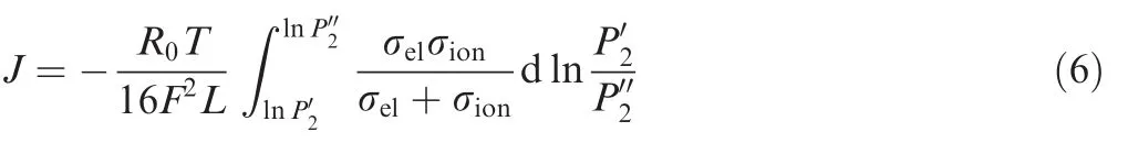
Three pieces of BSCF tubular membrane composed of Ba0.5Sr0.5Co0.8Fe0.2O3material with 0.5 mm wall thickness(inner diameter is 1.5 mm and outer diameter is 2.5 mm)and 500 mm length are selected for the experiment.They were jointly developed by Hefei Jianghang Aircraft Equipment Co.Ltd.in China and Dalian Institute of Chemical Physics in China.Fig.7 shows the SEM images of the membrane adopted in the PDCMSOGT system.It is indicated that there are discrete pores in the membrane.The relative density of the membrane is about 92%and the grain size is between 20 and 40 μm.The BSCF tubular membranes are placed vertically with one end open and the other end sealed with epoxy resin sealant.Be fore the experiment,the helium gastight test was conducted to verify the gastightness of tubular membranes.
Table 1 Working conditions of flat plate membrane module.
Fig.7 SEM images of membrane adopted in PDCMSOGT system.
Inside the membrane module experiment device of PDCMSOGT(Fig.8),three BSCF tubular membranes were installed vertically on the membrane brackets at the bottom in the metal pressure vessel made of nickel–chromium stainless steel(the outer diameter of the vessel was 50 mm,and the length was 620 mm),arranged in triangular form.The distance between the adjacent two membranes was 16.5 mm.The distance between the tubular membrane and vessel wall was 8 mm.Cooling water was supplied at the bottom of the metal pressure vessel to cool the sealing area and flowing gas.The high temperature vertical furnace was used to heat the permeable membrane module and the temperature of the membrane modules was measured by three S-type thermocouples.The compressed air was introduced to the metal pressure vessel and the air pressure in the vessel was regulated through the pressure regulator.The air pressure in the vessel was monitored by the pressure gauge monitor.The open ends of the three tubular membranes were connected through pipes and then connected to an oil-free vacuum pump.A vacuum pressure gauge was applied to monitor the vacuum pressure of the product gas.The mass flow rate of the product gas extracted by the vacuum pump was measured by the Mass flow meter 2.The oxygen concentration of product gas was measured by the oxygen analyzer.The temperatures of product gas and retained gas(lean-oxygen air)were measured by the Thermocouple 5 and Thermocouple 4 respectively.A needle valve was applied to adjust the mass flow rate of retained gas and the mass flow rate of it was monitored by the Mass flow meter 1.Pressure relief Valves 1 and 2 were used for venting of pressure vessel and vacuum pipeline in order to restore atmospheric pressure.
4.2.2.Experiment scheme
The main purpose of the experiment is to obtain the oxygen generation rate and oxygen concentration under different working conditions of the tube membrane,and then to calculate the permeation flux and oxygen recovery rate of the tube membrane.Working conditions are provided in Table 2.
4.3.Error analysis
The measuring instruments and their measurement errors are shown in Table 3.The instruments applied in the experiments were validated by the China’s National Institute of Metrology.The accuracy of the oxygen analyzers of the experiment sets of the EDCMSOGT and PDCMSOGT systems is adequate.Since the accuracy of the mass flow meters influences the results of the experiments significantly,the mass flow meters used in the experiments were customized by Brooks,which were accurate enough.Based on the data in Table 3,the uncertainty of the EDCMSOGT system and PDCMSOGT system is 1.499%and 1.537%respectively.The error level is within acceptable margin.

Table 3 Instruments used in experiment.
5.Analysis of experimental results
5.1.EDCMSOGT
In the experiment,under the working conditions that the input air flow rate is vin=6 L/min and the working temperatures of the membrane are Tw=500,600,650,700°C,DC power supplies power to the membrane at VDC=0.15,0.20,0.25,0.30 V,making the test number be 4×4.The influence of the temperature and voltage on the oxygen generation rate of the EDCMSOGT membrane is shown in Fig.9 from which thefollowing can be seen:
(1)When working temperature is between 500°C and 600°C,the oxygen generation rates are all relatively small and the amplification with temperature rise is small.When working temperature is between 600°C and 650°C,the oxygen generation rates have a significant increase and the amplification with temperature rise is large.Between the working temperatures of 650°C and 700°C,the oxygen generation rates are all very large,but the amplification with temperature rise slows down.
(2)When working temperature is between 500°C and 700°C,the oxygen generation rates increase with the increase of voltage and have the same trend with temperature rise.
By analyzing the experiment data of oxygen generation rates and by calculating the area specific resistance of plate membrane at different temperatures(Table 4),it can be concluded that ceramic conductivity of ceramic membrane materialincreases with temperature rise32and its surface resistance decreases with temperature rise.Meanwhile,it can be seen that the oxygen generation rate increases more rapidly when the temperature is between 500 °C and 650 °C and the increase rate of oxygen generation rate declines when the temperature is higher than 650°C.Also,the surface resistance reduces by 0.6 Ω·cm2when the temperature increases from 500 °C to 650 °C,whereas it only reduces by 0.03 Ω·cm2when temperature increases from 650 °C to 700 °C.Thus,it can be concluded that the working condition of a temperature higher than 650°C is favorable for the EDCMSOGT.Taking into account the temperature of input air provided by OBOGS comprehensively,we can conclude that the optimal working temperature of EDCMSOGT is 650°C.
By investigating the effect of input air flow rate on oxygen generation rate under the working temperature of 650°C,thefollowing conclusion is drawn from Fig.10(a)that with the increase of air flow rate,the oxygen generation rate increases slightly.Fig.10(b)shows the effect of inlet air flow rate on membrane oxygen recovery rate.It is concluded that:(A)under a certain voltage,as the air flow rate decreases,the oxygen recovery rate increases significantly;(B)at a certain air flow rate,with the increase of voltage,oxygen recovery rate increases significantly as well.The experimental results show that the oxygen recovery rate can reach 85%.
Under the conditions of 650°C working temperature,2 L/min air flow rate and 0.30 V voltage,when the permeation area of the membrane is 63.6 cm2,the measured oxygen generation rate is 0.358 L/min and the current is 102.8 A.By Eq.(9),the oxygen recovery rate η obtained is 85%(Fig.10(b)).By Eqs.(3)and(5),the permeation flux obtained is 5.63 mL/(min·cm2).Thus,under the same conditions,when the oxygen recovery rate η is 85%and the effective permeation area is 100 cm2, the calculated oxygen generation rate of 10 cm×10 cm flatplateceramicmembranemoduleis 0.563 L/min by Eq.(8).As the oxygen generation rate of 30 L/min is required for 2 persons under normal temperature and pressure(NTP)condition,according to the experiment data of one piece of membrane module,the EDCMSOGT system should be made of 54 pieces of membrane module to produce 30 L/min oxygen.

Fig.9 Influence of temperature on oxygen generation rate with EDCMSOGT(vin=6 L/min).
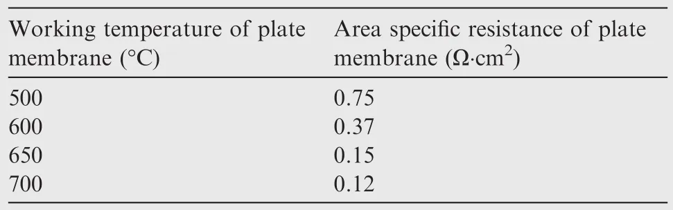
Table 4 Area specific resistance of plate membrane at different temperatures.
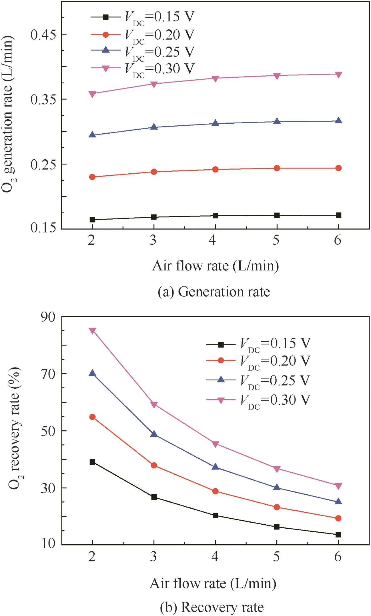
Fig.10 Influence of inlet air flow rate on membrane oxygen generation rate and recovery rate with EDCMSOGT(Tw=650°C).
The electric power consumed under different oxygen recovery rates by the EDCMSOGT system for 2 persons is evaluated by the same method and summarized in Table 5.
The membrane module experiment of EDCMSOGT is conducted under the condition that the inlet air pressure is atmospheric pressure,i.e.,0.1 MPa.Thus the oxygen partial pressure of the inlet air is 0.021 MPa.The pressure of the oxygen generated is 0.1 MPa,equal to the atmospheric pressure.So the process is a pressurization process for oxygen,which has been verified by Sundstrand5in Rock ford,State of Illinois.It is deduced that the pressure of the oxygen generated can reach 0.5 MPa when the inlet air pressure is 0.5 MPa which is the bleeding condition on board.
In summary,while the EDCMSOGT oxygen generation system achieves oxygen recovery rate of 85%,the electric power consumption is about 5.11 kW(Table 5).The gas flow rate under standard state can reach 30 L/min using 54 pieces of membrane module and the oxygen pressure can reach 0.5 MPa when inlet air pressure is 0.5 MPa.There fore,it is suitable for onboard application.
5.2.PDCMSOGT
Under the working condition 1 in Table 2,the effect of the lean-oxygen air flow rate,the operating temperature and the vacuum pressure of product gas extracted by vacuum pump on the oxygen production rate of the three BSCF tubular membranes is shown in Fig.11(a).It reveals that:
(1)When the working temperature,inlet air pressure and product gas outlet vacuum pressure are constant,the oxygen production rate tends to increase with the rise of lean-oxygen air flow rate,but the overall increase rate is slow.This result is consistent with the experiments conducted by Wang et al.33
(2)When the inlet air pressure,outlet vacuum pressure and lean-oxygen air flow rate are constant,the oxygen production rate tends to increase with the rise of temperature.The oxygen production rate under the condition of 850°C-0.012 MPa is in the range of 0.275–0.400 L/min,whereas the oxygen production rate under the condition of 600°C-0.012 MPa is in the range of 0.075–0.125 L/min.It is shown that the increase of the oxygen production ratewith temperatureisvery significant.
(3)When the working temperature,inlet air pressure and lean-oxygen air flow rate are constant,the oxygenproduction rate tends to increase with thefall of outlet vacuum pressure and the increase is very significant.
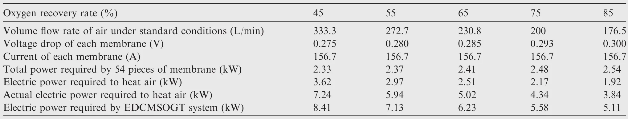
Table 5 Electric power consumed under different oxygen recovery rates by EDCMSOGT system.

Fig.11 Influence of flow rate of retained gas on oxygen generation rate and recovery rate with PDCMSOGT.
It can be inferred that the oxygen production rate tends to increase with the rise of lean-oxygen air flow,the rise of working temperature and thefall of vacuum pressure of the product gas,and especially the increasing tendency becomes remarkable with the rise of temperature and thefall of vacuum pressure.
Fig.11(b)shows the effects of theflow rate of retained gas,the working temperature and the vacuum pressure of product gas extracted by vacuum pump on the oxygen recovery rate.Thefollowing conclusions can be drawn:
(1)The oxygen recovery rate decreases with the rise of flow rate of retained gas.
(2)The oxygen recovery rate increases with the rise of operating temperature.
(3)The oxygen recovery rate increases with thefall of vacuum pressure of product gas.
Under the working condition 2 in Table 2,it is observed that the flow meter 2 which measures the mass flow rate of product gas shows that there is a slight out flow at the beginning,but theflow decreases to zero very quickly and then there is no more out flow.This is a result of the reduction of oxygen partial pressure difference between both sides of membranes.At the beginning,the oxygen partial pressure of the inlet air in metal pressure vessel is 0.105 MPa and the product gas oxygen partial pressure is 0.021 MPa,leading to a very big oxygen partial pressure difference.Thus,the oxygen permeates into the product gas.Then the oxygen concentration of the product gas rises gradually and its oxygen partial pressure increases gradually as product gas flows out through flow meter 2.With the increase of oxygen partial pressure of product gas,the oxygen partial pressure difference between both sides of membrane decreases,leading to the decrease of the oxygen generation rate.When the oxygen partial pressure difference is not sufficient to drive oxygen ion-electron conduction,the oxygen production stops.It can be deduced from the experiment that when the inlet air pressure provided on board is 0.5 MPa,the oxygen generation system cannot produce the oxygen with pressure larger than 0.105 MPa.Thus it does not meet the requirement that the pressure of product gas for onboard oxygen production should be greater than 0.18 MPa.
Under working conditions 3 and 4 in Table 2,the oxygen production rates of three pieces of BSCF tubular membranes are measured.The effect of vacuum pump on oxygen production rate is shown in Fig.12.It can be seen from the figure that comparing the conditions with vacuum pump(the vacuum pressure is 0.012 MPa)and those without,the oxygen generation rate reduces by 55%and 67%respectively when the flow rates of retained gas are 2 L/min and 6 L/min.In addition,with the vacuum pump,the oxygen generation rate increases by 110%with the rise of flow rate of the retained gas from 2 L/min to 6 L/min,whereas without the vacuum pump,the oxygen generation rate only increases by 55%with the rise of flow rate of the retained gas.The experiment indicates that when the outlet vacuum condition is restored,the oxygen generation rate and oxygen recovery rate can be increased,which is consistent with the study of Zhu et al.34So,under the onboard inlet air pressure of 0.5–1.1 MPa,the onboard ceramic oxygen generation system adopting oxygen partial pressure driven oxygen ion-electron conduction can produce oxygen only by applying oxygen extraction mode of vacuum pump.
The maximum oxygen recovery rate appears under the conditions that the inlet pressure is 0.5 MPa,the temperature is 850°C,the vacuum pressure of product gas is 0.012 MPa(absolute)and flow rate of retained gas is 2 L/min.By Eq.(7),the permeation area of the three pieces of tubular membranes is calculated to be 92.25 cm2.The oxygen generation rate measured by test is 0.2717 L/min,and by Eq.(9),we get that the oxygen recovery rate is 65%,as shown under the condition of 850°C-0.012 MPa in Fig.11(b).In order to produce 30 L/min oxygen,the PDCMSOGT system should be made of 332 pieces of tubular membrane module.By Eq.(10),the electric power consumption for air heating with 65%oxygen recovery rate is 3.63 kW.If the heating efficiency is considered as 50%,the actual power consumption is 7.26 kW.As shown under the condition of 850°C-0.012 MPa in Fig.11(b),the oxygen recovery rate varies from 35%to 65%.When the oxygen generation rate of PDCMSOGT system is 30 L/min(NTP),the actual electric power consumed by PDCMSOGT system,under different oxygen recovery rates,is calculated and shown in Table 6.

Fig.12 Influence of outlet vacuum on oxygen generation rate with PDCMSOGT.

Table 6 Actual electric power consumed by PDCMSOGT system.
In summary,while the oxygen generation rate of the PDCMSOGT oxygen generation system is 30 L/min and the oxygen recovery rate is 65%,the electric power consumption is about 7.26 kW.At the same time,the inlet air pressure is 0.5 MPa and the pressure of product gas is 0.012 MPa.However,vacuum pump and supercharging device are needed to meet onboard conditions.
5.3.Comparison of experimental results
To validate the experimental results obtained in this work,it is necessary to make a comparison with other existing experimental data.Due to the difference in the membrane material,application field and working conditions,it is difficult to find appropriate examples to compare with our results.The possible example for comparison with our results of EDCMSOGT oxygen generation system is found from the work by Zhou etal.35who reviewed the Ba0.5Sr0.5Co0.8Fe0.2O3-δ-based cathodes for solid-oxidefuel cells.They reported the area specific resistance of membrane of 0.058 atworking temperature750 °C and thatof 0.62 at600 °C with Ba0.5Sr0.5Co0.8Fe0.2O3-δ-based cathodes.36By comparing the experimental data of those authors with our results in Table 4 in this paper,it is shown that the area specific resistance exhibits similar trend and the same order.
The possible example for comparison with our results of PDCMSOGT oxygen generation system is found from the work by Wang et al.37who investigated the structure and oxygen permeability of the pure BSCF and the dual-phase membrane at different temperatures by experiment method.The oxygen permeation flux of the BSCF membrane they obtained is 0.001 L/(min·cm2)at the working temperature of 850 °C.In their experiment,the air flow rate on air side is 0.15 L/min,the membrane thickness is 1.99 mm and the membrane area is 0.85 cm2.They did not say the working pressure.In this paper,the oxygen generation rate of the BSCF-based PDCMSOGT oxygen generation system is 0.2717 L/min under the working conditions that the temperature is 850°C,the air inlet pressure is 0.5 MPa,the vacuum pressure of product gas is 0.012 MPa(absolute),theflow rate of retained gas is 2 L/min,the membrane thickness is 0.5 mm and membrane area is 92.25 cm2.By Eq.(8),the oxygen permeation flux is 2.94 mL/(min·cm2).Since the difference in the membrane thickness and working conditions,deviation exists and the oxygen permeation flux is higher compared with Ref.37The reason can be explained as follows:(A)the oxygen permeation flux decreases with the increase of the membrane thickness according to Eq.(6)and the experimental results obtained by Ref.37;(B)the oxygen permeation flux increases with the increase of the air inlet pressure by analyzing the results in Figs.11(a)and 12;(C)the oxygen permeation flux increases greatly under the condition with vacuum pump according to Fig.12 and it was not mentioned that the vacuum pump was used in the Ref.37Thus,the comparisons validates the accuracy of the experimental results in this paper.
6.Conclusions
In combination with the demand of the OBOGS of EDCMSOGT and PDCMSOGT,the present paper compares their performance under the same onboard bleeding conditions.
(1)Oxygen produced by both EDCMSOGT and PDCMSOGT is pure(both oxygen concentration values measured are 99.9%,above 99.5%).
(2)Oxygen recovery rate of EDCMSOGT is 85%,higher than 65%of PDCMSOGT.The bleeding air consumption is less(the air saved is 54.3 L/min).The air saved accounts for 30.8%of the bleeding air consumption.
(3)Electric power consumed by EDCMSOGT is 5.11 kW,less than 7.26 kW of PDCMSOGT.The saved power is 2.15 kW,and the saved power accounts for 42.1%of the consumed power.
(4)For the pressure of the output product gas,the EDCMSOGT meets the requirements of output pressure.At the same time,the pressure of the output product gas(oxygen)is not limited by the input air pressure and can be pressurized by itself according to the demand.This con forms to the existing onboard bleed conditions and the requirements of output pressure of oxygen.Whereas,the PDCMSOGT needs a vacuum pump and supercharging device to meet the requirements for onboard bleeding conditions.These two equipments add difficulty to onboard oxygen generation application due to their volume and weight.
The above results indicate that the EDCMSOGT can meet the existing onboard bleed conditions and the performance requirements of ceramic oxygen generation system.It has the advantages of oxygen pressurization,low air consumption and relatively low power consumption.It is there fore a better choice for OBOGS than the PDCMSOGT.Further research needs to be carried out on the EDCMSOGT to satisfy the requirements of aircraft engineering application as soon as possible.
1.Roettger B,Curran P.Ceramic membranes as electrochemical CBR filters.Proceedings of the American Defense Preparedness Association.1990.
2.Dos SL,Lucato SE,Sudre OH,Marshall DB.A method for assessing reactions of water vapor with materials in high-speed,high-temperatureflow.J Am Ceram Soc 2011;94(Suppl.1):186–95.
3.Wang YG,Fei WF,Fan Y,Zhang LG,Zhang WG,An LA.Silicoaluminum carbonitride ceramic resist to oxidation/corrosion in water vapor.J Mater Res 2006;21(7):1625–8.
4.Nernst W.On the electrolytic conduction of solid bodies at high temperatures.Z Electrochem 1989;6(2):41–3.
5.Roettger BF.Oxygen purification and compression capabilities of ceramic membranes.Safe J 1992;22(3):31–6.
6.Sun WP,Shi Z,Wang ZT,Liu W.Bilayered BaZr0.1Ce0.7Y0.2O3-δ/Ce0.8Sm0.2O2-δelectrolyte membranes for solid oxidefuel cells with high open circuit voltages.J Membr Sci 2015;476(2):394–8.
7.Sun WP,Shi Z,Qian J,Wang ZT,Liu W.In-situ formed Ce0.8Sm0.2O2-δ@Ba(Ce,Zr)1-x(Sm,Y)xO3-δcore/shell electronblocking layer towards Ce0.8Sm0.2O2-δ-based solid oxidefuel cells with high open circuit voltages.Nano Energy 2014;8(9):305–11.
8.Liu ZB,Ding D,Liu MF,Ding XF,Chen DC,Li XX,et al.Highperformance,ceria-based solid oxidefuel cells fabricated at low temperatures.J Power Sources 2013;241(11):454–9.
9.Sun WP,Liu W.A novel ceria-based solid oxidefuel cell freefrom internal short circuit.J Power Sources 2012;217(11):114–9.
10.Wei YY,Liao Q,Li Z,Wang HH,Feldhof f A,Caro J.Partial oxidation of methane in hollow-fiber membrane reactors based on Alkaline-Earth metal-free CO2-tolerant oxide.AIChE J 2014;60(10):3587–95.
11.Schwiedernoch R,Tischer S,Correa C,Deutschmann O.Experimental and numerical study on the transient behavior of partial oxidation of methane in a catalytic monolith.Chem Eng Sci 2003;58(3–6):633–42.
12.Zhu XF,Li QM,He YF,Cong Y,Yang WS.Oxygen permeation and partial oxidation of methane in dual-phase membrane reactors.J Membr Sci 2010;360(1–2):454–60.
13.Yang ZB,Zhang YW,Ding WZ.Investigation on the re forming reactions of coke-oven-gas to H2and CO in oxygen-permeable membrane reactor.J Membr Sci 2014;470(11):197–204.
14.Zhang YW,Liu J,Ding WZ,Lu XG.Per formance of an oxygenpermeable membrane reactor for partial oxidation of methane in coke oven gas to syngas.Fuel 2011;90:324–30.
15.Zhang YW,Li Q,Shen PJ,Liu Y,Yang ZB,Ding WZ,et al.Hydrogen amplification of coke oven gas by re forming of methane in a ceramic membrane reactor.Int J Hydrogen Energy 2008;33(13):3311–9.
16.Wei YY,Wang YJ,Tang J,Li Z,Wang HH.Oxy-fuel combustion for CO2capture using a CO2-tolerant oxygen transporting membrane.AIChE J 2013;59(10):3856–62.
17.Rezvani S,Huang Y,Wright DM,Hewitt N,Mondol JD.Comparative assessment of coal fired IGCC systems with CO2capture using physical absorption,membrane reactors and chemical looping.Fuel 2009;88(12):2463–72.
18.Sunarso J,Baumann S,Serra JM,Meulenberg WA,Liu S,Lin YS,et al.Mixed ionic–electronic conducting(MIEC)ceramic-based membranes for oxygen separation.J MembrSci2008;320(1–2):13–41.
19.Girish SK,Detlev D,inventor;Be Aerospace Inc.,assignee.Hybrid on-board generation of oxygen for aircraft passengers.United States patent US 20130312745;2013 Nov 28.
20.Belinda FR,Richard WR,Patrick DC inventor;Sundstrand Corporation,assignee.Method of generating oxygen from an air stream.United States patent US 005169415;1992 Dec 8.
21.Availablefrom:http://www.aki.che.tohoku.ac.jp/~koyama/html/research/SOFC.html.
22.Samson AJ,Søgaard M,Hendriksen PV.(Ce,Gd)O2-δbased dual phase membranes for oxygen separation.J Membr Sci 2014;470(11):178–88.
23.Chatzichristodoulou C,Søgaard M,Glasscock J,Kaiser A,Foghmoes SPV,Hendriksen PV.Oxygen permeation in thin,dense Ce0.9Gd0.1O1.95-δmembranes II.Experimental determination.J Electrochem Soc 2011;158(5):73–83.
24.Ganesan P,Colon H,Haran B,Popov BN.Per formance of La0.8Sr0.2CoO3coated NiO as cathodes for molten carbonatefuel cells.J Power Sources 2003;115(1):12–8.
25.Zheng Y,Ran R,Qiao SZ,Shao ZP.Study on oxygen activation and methane oxidation over La0.8Sr0.2MnO3electrode in singlechamber solid oxidefuel cells via an electrochemical approach.Int J Hydrogen Energy 2012;37(5):4328–38.
26.Goza´lvez-Zafrilla JM,Santafe´-Moros A,Escola´stico S,Serra JM.Fluid dynamic modeling of oxygen permeation through mixed ionic–electronic conducting membranes.J Membr Sci 2011;378(1–2):290–300.
27.Kim JP,Magnone E,Park JH,Lee Y.Oxygen production of tubular module with La0.6Sr0.4Ti0.3Fe0.7O3-δcoated Ba0.5Sr0.5Co0.8Fe0.2O3-δmembrane.J MembrSci2012;403(6):188–95.
28.Li HB,Zhu XF,Liu Y,Wang WP,Yang WS.Comparative investigation of dual-phase membranes containing cobalt and iron-based mixed conducting perovskite for oxygen permeation.J Membr Sci 2014;462(7):170–7.
29.Tan X, Pang Z, Li K. Oxygen production using La0.6Sr0.4Co0.2Fe0.8O3-α(LSCF)perovskite hollow fibre membrane modules.J Membr Sci 2008;310(1–2):550–6.
30.Farooq S,Rathor MN,Hidajat K.A predictive model for a kinetically controlled pressure swing adsorption separation process.Chem Eng Sci 1993;48(24):4129–41.
31.Nielsen KA,Solvang M,Nielsen SBL,Dinesen AR,Beeaff D,Larsen PH.Glass composite seals for SOFC application.J Eur Ceram Soc 2007;27(2–3):1817–22.
32.Richter R.Basic investigation into the production of oxygen in a solid electrolyte processAIAA 16th thermophysics conference.Reston:AIAA;1981.
33.Wang H,Wang R,Liang DT,Yang WS.Experimental and modeling studies on Ba0.5Sr0.5Co0.8Fe0.2O3-δ(BSCF)tubular membranes for air separation.J Membr Sci 2004;243(1–2):405–15.
34.Zhu XF,Sun SM,Cong Y,Yang WS.Operation of perovskite membrane under vacuum and elevated pressures for high-purity oxygen production.J Membr Sci 2009;345(1–2):47–52.
35.Zhou W,Ran R,Shao ZP.Progress in understanding and development of Ba0.5Sr0.5Co0.8Fe0.2O3-δ-based cathodes for intermediate-temperature solid-oxidefuel cells:A Review.J Power Sources 2009;192(2):231–46.
36.Peng RR,Wu Y,Yang LZ,Mao ZQ.Electrochemical properties of intermediate-temperature SOFCs based on proton conducting Sm-doped BaCeO3electrolyte thin film.Solid State Ionics 2006;177(3–4):389–93.
37.Wang HH,Yang WS,Cong Y,Zhu XF,Lin YS.Structure and oxygen permeability of a dual-phase membrane.J Membr Sci 2003;224(1–2):107–15.
Jiang Dongsheng became a senior engineer in Hefei Jianghang Aircraft Equipment Co.Ltd.in 1999.He received the M.S.degree in aircraft design engineering from School of Aeronautic Science and Engineering,Beihang University in 2009.He is currently a Ph.D.candidate in Beihang University.His research areas include onboard oxygen systems and onboard fuel inerting systems.
Bu Xueqin received her Ph.D.degreefrom Beihang University in 2010,and now she is a lecturer in School of Aeronautic Science and Engineering,Beihang University.Her areas of research include aircraft environment control,lifesaving and aircraft icing.
30 September 2015;revised 15 October 2015;accepted 11 April 2016
Available online 22 June 2016
Ceramic membrane;
Electricity driven;
Experiment;
Onboard oxygen generation;Pressure driven
©2016 Chinese Society of Aeronautics and Astronautics.Production and hosting by Elsevier Ltd.Thisisan open access article under the CC BY-NC-ND license(http://creativecommons.org/licenses/by-nc-nd/4.0/).
*Corresponding author.
E-mail addresses:jiangds922@163.com(D.Jiang),buxueqin@buaa.edu.cn(X.Bu).
Peer review under responsibility of Editorial Committee of CJA.
Production and hosting by Elsevier
http://dx.doi.org/10.1016/j.cja.2016.06.003
1000-9361©2016 Chinese Society of Aeronautics and Astronautics.Production and hosting by Elsevier Ltd.
This is an open access article under the CC BY-NC-ND license(http://creativecommons.org/licenses/by-nc-nd/4.0/).
杂志排行

CHINESE JOURNAL OF AERONAUTICS的其它文章
- Numerical simulation of aerodynamic interaction for a tilt rotor aircraft in helicopter mode
- Investigation of MHD power generation with supersonic non-equilibrium RF discharge
- Transition study of 3D aerodynamic configures using improved transport equations modeling
- Numerical investigation of aerodynamic flow actuation produced by surface plasma actuator on 2D oscillating airfoil
- Characterization of component interactions in two-stage axial turbine
- Numerical study of aerodynamic characteristics of FSW aircraft with different wing positions under supersonic condition