Numerical stress-deformation analysis of cut-off wall in clay-core rockfill dam on thick overburden
2016-04-18ZijinWngErihBuer
*,Zi-jin Wng,Erih Buer
aCollege of Water Conservancy and Hydropower Engineering,Hohai University,Nanjing 210098,China
bZhejiang Design Institute of Conservancy and Hydroelectric Power,Hangzhou 310002,China
cInstitute of Applied Mechanics,Graz University of Technology,Graz 8010,Austria
Numerical stress-deformation analysis of cut-off wall in clay-core rockfill dam on thick overburden
Si-hong Liua,Liu-jiang Wanga,*,Zi-jian Wangb,Erich Bauerc
aCollege of Water Conservancy and Hydropower Engineering,Hohai University,Nanjing 210098,China
bZhejiang Design Institute of Conservancy and Hydroelectric Power,Hangzhou 310002,China
cInstitute of Applied Mechanics,Graz University of Technology,Graz 8010,Austria
Available online 10 November 2016
The cut-off wall in a clay-core rockfill dam built on a thick overburden layer is subjected to a large compressive pressure under the action of the loads such as the dead weight of both the dam and the overburden layer,the frictional force induced by the differential settlement between the cut-off wall and surrounding soils,and the water pressure.Thus,reduction of the stress of the cut-off wall has become one of the main problems for consideration in engineering design.In this paper,numerical analysis of a core rockfill dam built on a thick overburden layer was conducted and some factors inf l uencing the stress-strain behaviors of the cut-off wall were investigated.The factors include the improvement of the overburden layer,the modeling approach for interfacial contact between the cut-off wall and surrounding soils,the modulus of the cut-off wall concrete,and the connected pattern between the cut-off wall and the clay core.The result shows that improving the overburden layer, selecting plastic concrete with a low modulus and high strength,and optimizing the connection between the cut-off wall and the clay core of the dam are effective measures of reducing the deformations and compressive stresses of the cut-off wall.In addition,both the Goodman element and the mud-layer element are suitable for simulating the interfacial contact between the cut-off wall and surrounding soils.
Overburden layer;Core rockfill dam;Cut-off wall;Numerical analysis;Stress and deformation analysis
1.Introduction
In recent years,the number of clay-core rockfill dams built on a thick overburden layer has been increasing gradually.The anti-seepage treatment of the thick overburden layer is very important in the design of these dam projects for ensuring safe operation.In general,there are two methods of treatment:one is to excavate the overburden deposits under the clay core,and the other is to build concrete cut-off walls inside the overburden deposits.The latter is now widely used in China(Gao, 2000).As the concrete cut-off wall is built under the clay core, it is subjected to the large dead load of the upper dam body and the water head difference between upstream and downstream water level during the construction and impounding.As a result,the stress-deformation characteristics of cut-off walls are very complex.
A centrifugal model test,field monitoring,and the numerical analysis method have usually been used to study the behavior of cut-off walls.For example,the interaction mechanism between the cut-off wall and surrounding soils in the upstream cofferdam of the Three Gorges Project has been investigated through a centrifugal model test and numerical analysis(Bao,2007).The strain and deformation of this cut-off wall were monitored(Zhang et al.,2000;Cheng,2004). Many numerical analyses have been carried out to investigate the interaction of overburden soils and the cut-off wall,and the inf l uence of the cut-off wall's thickness,the properties of alluvium deposits,the valley boundary,and the cut-off wall construction sequence on the stress-deformation behaviors of cut-off walls(Lu and Wang,1998;Wang et al.,2006;Li et al., 2007;Jia et al.,2008;Pan et al.,2013;Ding et al.,2013).
In this study,numerical analysis of a clay-core rockfill dam built on a deep overburden layer was conducted and some factors affecting the stress-strain behaviors of the cut-off wall were investigated comprehensively.The factors investigated include the improvementofthe overburden layer,the modeling approach for interfacial contact between the cut-off wall and its surrounding soil,the modulus of cut-off wall concrete,and the connected pattern between the cut-off wall and the clay core.
2.Finite element analysis for rockfill dam
In this study,two-dimensional finite element analysis was carried out on a clay-core rockfill dam,which was built on an overburden layer with a thickness ranging from 39.5 m to 81.3 m.Fig.1 shows a typical cross-section of this rockfill dam.The dam had a height of 120 m and a crest width of 12 m.Both the upstream and downstream slopes were 1:2.The slopes of the core wall,f i lter zones,and transition zones were 1:0.25.The normal water storage level of the dam reservoir is 2485 m.The overburden layer of the dam foundation is composed of sand alluvium and talus deposit.Along the depth, the overburden foundation is divided into six layers:layer 1, spreading over the river bed,is composed of sand and gravel with a loose structure and moderate permeability;layer 2 is composed of silty clay with a percentage of silt of 54%and a percentage of clay of 26%;layers 3 and 4 are composed of coarse sand that contains gravel and gravel that contains mud, with a loose structure and moderate permeability;layer 5 is composed of coarse sand that contains gravel with a percentage of silt of 32%and a percentage of clay of 8%;and layer 6 is composed of gravel that contains mud with a loose structure and moderate permeability.
Layers 1 and 2 were excavated,and layer 3 was improved using vibro-replacement stone columns.Meanwhile,a 1.2 mthick concrete cut-off wall,embedded in the bedrock with a depth of 0.5 m,was constructed inside the overburden layer. The curtain grouting was carried out in the bedrock under the cut-off wall to ensure a reliable connection between the cut-off wall and the bedrock.The cut-off wall was connected with the clay core of the dam through a gallery.
Static and dynamic analysis software for the dam's stress and seepage(Liu,2008;Xiang et al.,1991),which was developed on the basis of the Biot consolidation theory for saturated soils to take into account the coupling between the seepage and the stress field,was used in this study.
The finite element mesh for the dam body and the overburden foundation consisted of 2631 elements and 2523 nodes. As shown in Fig.2,four columns of meshes were used for the 1.2 m-thick cut-off wall and 136 contact elements were arranged between the cut-off wall and surrounding soils.If the hollow junction was used for the connection between the cutoff wall and clay core,the modulus in the shadow area on the right side of Fig.2 was set to be 0.According to the processes of dam construction and impounding,34 steps were set in the fi nite element calculation.The process of dam fi lling from the dam base to an elevation of 2440.0 m was simulated in the fi rst 14 steps,which took 495 days.Then,the process of impounding from the river bed to an elevation of 2437.0 m was simulated in steps 15 to 20,which took 30 days.After that,the process of the dam filling from the elevation 2440.0 m to an elevation of 2480.0 m was simulated in steps 21—28, which took 285 days.The process of impounding from the elevation 2437.0 m to 2475.0 m was simulated in the last f i ve steps,which took 60 days.In the simulation of impounding, the water pressure and water head were applied on the upstream face of the clay core.
The consolidated settlement of the overburden foundation has already been stable over hundreds of thousands of years. Thus,the displacement of the overburden foundation was set to zero at the beginning of the calculation.However,the initial earth stress of the overburden foundation should be considered.It was calculated using the unbalanced force iterative method.
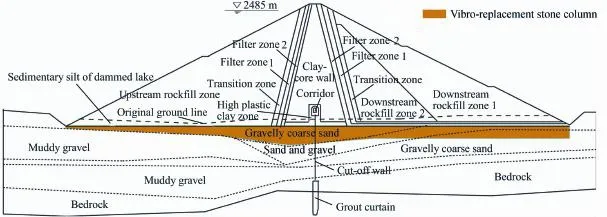
Fig.1.Typical cross-section of rockfill dam.
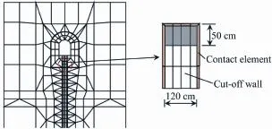
Fig.2.Finite element mesh at top of cut-off wall.
In the calculation,the linear elastic model was used for the concrete cut-off wall,with the elastic modulus E being 22 GPa and the Poisson's ratio being 0.167.The Duncan-Chang(E-B) model was used for rockfill materials(Duncan and Chang, 1970).The Young's modulus E and bulk modulus Btof this constitutive model are expressed as
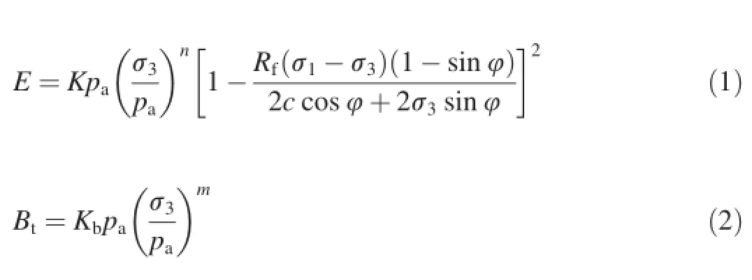
Under unloading and reloading conditions,the elastic modulus E is expressed as
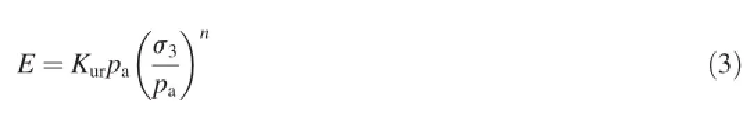
where σ1and σ3are the major and minor principle stresses, respectively;pais the atmosphere pressure;Rfis the failure ratio;K is the modulus number;Kbis the bulk modulus number;n and m are the exponents;Kuris the modulus number under unloading and reloading conditions;φ is the internal friction angle,and φ=φ0-Δφlg(σ3/pa),with φ0being the initial internal friction angle and Δφ being the increment of internal friction angle;and c is the cohesive strength.The parameters determined by laboratory tests are shown in Table 1,where ρ is the density and ksis the permeability coeff i cient.
3.Results and discussion
3.1.Stress and deformation of dam
Fig.3 shows the contour distributions of the settlement and the major principal stress of the dam(including the overburden foundation)after impounding.The maximum settlement of the dam is 170 cm,occurring at the downstream side near the top surface of the overburden foundation.
For the clay-core rockfill dam located on the hard bedrock, an inconsistent deformation between the clay core and its adjacent rockfill probably occurs due to their different deformation moduli.Therefore,the stress in the clay core will be partly transferred to the adjacent rockfill,this is the so-called arching effect.However,for the dam analyzed in this study, due to the large compression deformation of the overburden layer and the uplift force from the cut-off wall,the arching effect between the clay core and the adjacent rockfill is not pronounced(Fig.3).That is to say,the thick overburden layer plays an important role in reducing the arching effect.
3.2.Effect of improvement of overburden layer on stress-strain behaviors of cut-off wall
As the deformation modulus of the overburden layer is much lower than that of the concrete cut-off wall,the settlement of the overburden layer caused by dam filling and impounding will be larger than that of the concrete cut-off wall.Therefore,an uneven settlement exists between the cut-off wall and the foundation,resulting in friction between the cut-off wall and the surrounding foundation.This friction is the major load affecting the stress and deformation of the cut-off wall.
To reduce this uneven settlement,the overburden layer near the surface should be reinforced.In this project,layers 1 and 2 are excavated,and layer 3,composed of coarse sand thatcontains gravel,was improved with vibro-replacement stone columns.Based on experiences from similar projects,the main parameters of the E-B model for the improved layer 3 were considered to be K=800,Kb=350,and m=0.05.Meanwhile,a scheme without improvement of layer 3 was also investigated to verify the improvement effect,and the corresponding parameters were set to be K=250,Kb=72,and m=0.26.
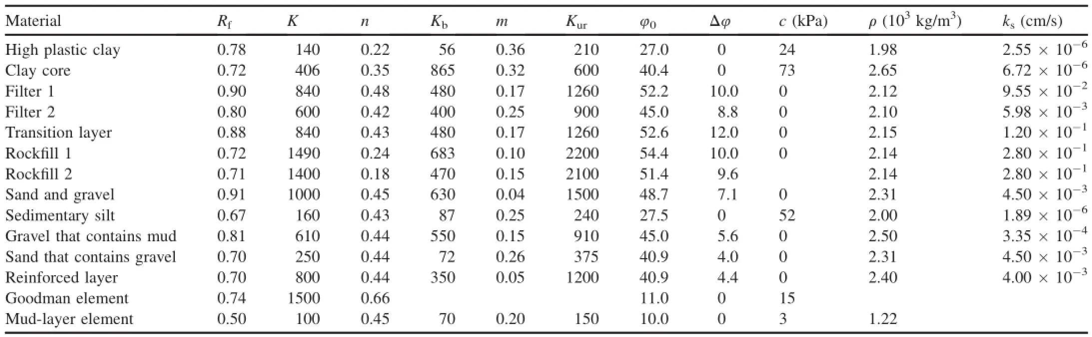
Table 1Parameters in calculation.
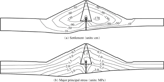
Fig.3.Contours of settlement and major principal stress after impounding.
Table 2 shows the comparison of the displacements at the top of the cut-off wall with and without improvement of the overburden layer 3.Both the horizontal displacement and vertical displacement(settlement)are reduced signif i cantly after the overburden layer 3 is improved.Table 3 shows the comparison of the principal stresses of the cut-off wall with and without improvement of the overburden layer 3.Fig.4 shows the distribution of the major and minor principal stresses of the cut-off wall along the depth with and without improvement of the overburden layer 3 at completion of the dam.It can be seen that,after the improvement of the overburden layer 3,the major principal stress(compression)of the cut-off wall is reduced signif i cantly,with a mean decrease of 5—10 MPa along the depth.Therefore,the crushing of the cutoff wall can be diminished effectively with the improvement of layer 3.On the other hand,the minor principal stress of the cut-off wall changes slightly.
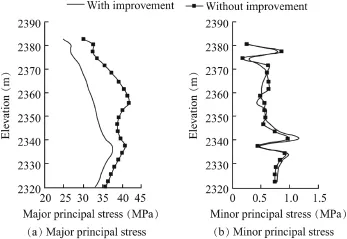
Fig.4.Distribution of principal stresses of cut-off wall along depth with and without improvement of overburden layer 3 at completion of dam.
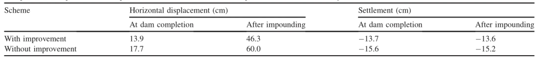
Table 2Comparison of displacements at top of cut-off wall with and without improvement of overburden layer 3.

Table 3Comparison of major and minor principal stresses of cut-off wall with and without improvement of overburden layer 3.
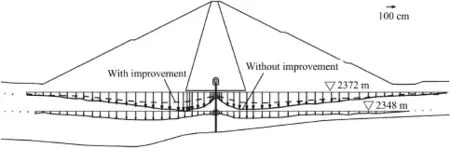
Fig.5.Comparison of settlement of alluvium deposit with and without improvement of overburden layer 3.
Figs.5 and 6 show the settlements and the contours of the major principal stress of the alluvium deposit with and without improvement of the overburden layer 3,respectively.As we can see from these two f i gures,the settlement in the improved overburden layer is reduced signif i cantly,while the major principal stresses in the improved foundation increase.That is to say,when the foundation is improved,the stresses caused by the dam filling and impounding increase in the overburden layer and decrease in the cut-off wall,resulting in the decrease of the arching effect between the cut-off wall and its surrounding rock/soils.Therefore,the improvement of the overburden layerisan effective measure ofreducing the deformations and compressive stresses of the cut-off wall.
3.3.Inf l uence of interface elements between cut-off wall and surrounding soils on stress-strain behaviors of cutoff wall
Due to the large differences in the deformation moduli for different materials,the displacements of the cut-off wall and its surrounding soilsare obviously inconsistent.Therefore, methods of simulating the interfacial contact between the cutoff wall and its surrounding soils are highly important.In the numerical study,three different interface elements were investigated:the Goodman element with a finite thickness (Goodman et al.,1968),the mud-layer element(Li et al.,2007), and the frictionless element.The Goodman element is the most widely used to simulate interfacial contact between two materials that have greatly different moduli.The thickness of this element is zero.During the construction of the cut-off wall,a mud layer is usually produced between the cut-off wall and foundation,which inf l uences the mechanical behavior of the interface and changes the loads on the cut-off wall and foundation.For the cofferdam in the Miyun Reservoir,it was found that the thickness of the mud layer at the interfacial contact between the cut-off wall and its surrounding soils was about 3—5cm,andthemudadheredtothecut-offwallwasinaplastic state with extremely low shear strength.In this analysis,the mud-layer element was adapted and the thickness of the mudlayer element was set to 3 cm.In order to evaluate the inf l uence of the friction force on the cut-off wall,a frictionless elementwasusedforcontrasting,withtheassumptionthatthere was no friction between the cut-off wall and its surrounding soils.In this study,the parameters for both the Goodman element and the mud-layer element were respectively taken from the PubugouDam(Chen et al.,2005)and the cofferdam in the Three Gorges Project(Li and Cheng,2005),as listed in Table 1.For the frictionless element,the shear modulus along the interface was set to zero.
Table 4 shows the principal stresses of the cut-off wall simulated using three different interface elements.Fig.7 shows the distribution of the principal stresses of the cut-off wall simulated using three different interface elements at completion of the dam.The results show that the principal stresses of the cut-off wall simulated using the frictionless elements are distributed evenly along the depth and their values are lower than those simulated using other two interface elements.When the frictionless elements are used,the stresses of the cut-off wall are mainly caused by the self-weight of the dam and the water pressure;the friction between the cut-off wall and its surrounding soils is neglected.The principal stresses in the cutoff wall simulated using the Goodman elements and the mudlayer elements are almost the same,indicating that these two interface elements are suitable for simulating the contact between the cut-off wall and its surrounding soils.
3.4.Inf l uence of elastic modulus of cut-off wall concrete on stress-strain behaviors of cut-off wall
There are two kinds of concretes that are frequently used for cut-off walls:normal concrete and plastic concrete.The elastic modulus of normal concrete is about 25.5—36.0 GPa, which is 5—10 times larger than that of plastic concrete.In this study,three different elastic moduli of cut-off wall concrete (10 GPa,22 GPa,and 35 GPa)were selected to investigate their inf l uence on the stress-strain behavior of the cut-off wall.

Fig.6.Contours of major principal stress in alluvium deposit with and without improvement of overburden layer 3(units:MPa).

Table 4Major and minor principal stresses of cut-off wall simulated with different interface elements between cut-off wall and its surrounding soils.
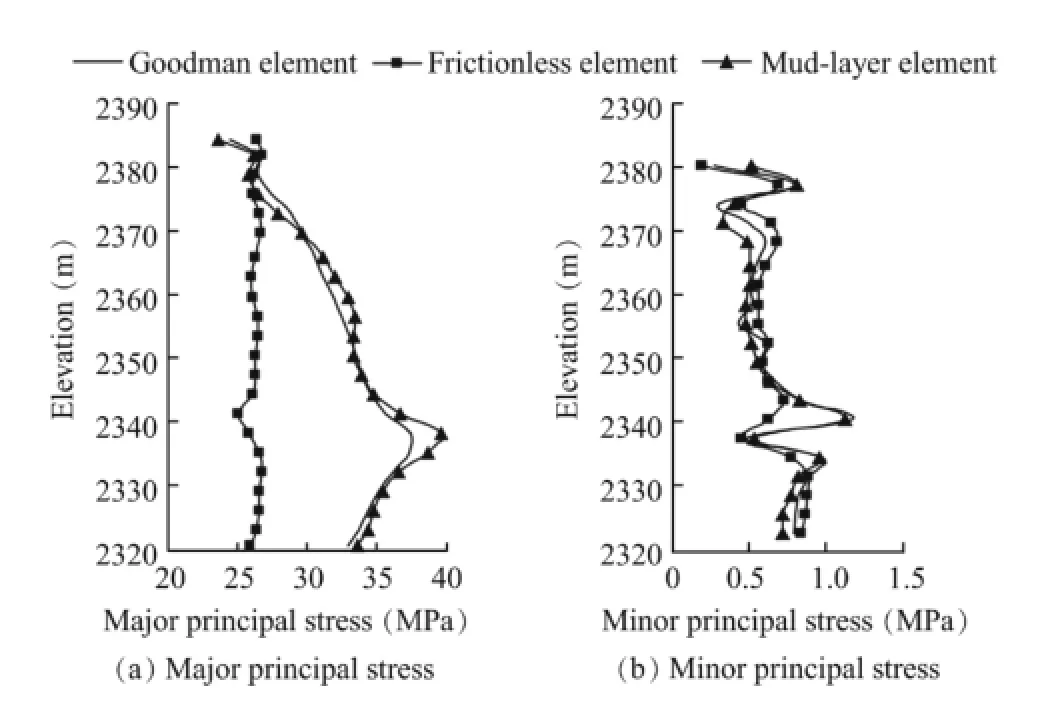
Fig.7.Distribution of major and minor principal stresses of cut-off wall along depth calculated by different interface elements between cut-off wall and its surrounding soils at completion of dam.
Table 5 shows a comparison of the displacements at the top of the cut-off wall with different elastic moduli of concrete.It can be seen that the vertical displacement(settlement)of the cut-off wall increases with the decreasing elastic modulus of concrete,while the horizontal displacement of the cut-off wall changes slightly with different elastic moduli of concrete. Table 6 shows the principal stresses of the cut-off wall with different elastic moduli of concrete.Fig.8 shows the distribution of the principal stresses of the cut-off wall with different elastic moduli of concrete at the completion of the dam.The results show that the major principal stress of the cut-off wall increases with the elastic modulus of concrete, while the minor principal stress is not much affected by the elastic modulus of concrete.The reduction of the major principal stress of the cut-off wall with a low elastic modulus of concrete is mainly attributed to the decrease of the relative settlement between cut-off wall and surrounding soils.
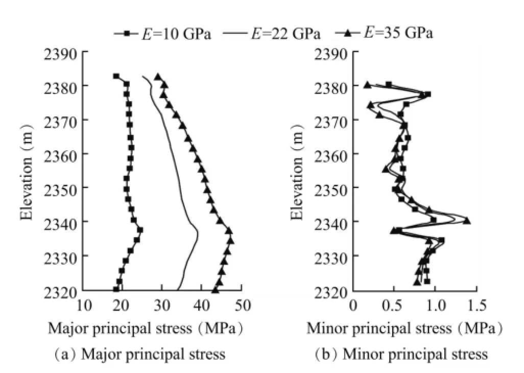
Fig.8.Distribution of major and minor principal stresses of cut-off wall with different elastic moduli along depth at completion of dam.
For common concrete,the strength increases with the elastic modulus.In this case,although the compressive stress of the cut-off wall decreases when concrete with a lower elastic modulus is used,the crushing of the cut-off wall may occur if the compressive stress exceeds the compressive strength of the cut-off wall.Therefore,selection of a reasonable plastic concrete,preferably with a lower modulus andrelatively higher compressive strength,is very important in the construction of cut-off walls.

Table 5Comparison of displacement at top of cut-off wall with different concrete elastic moduli.
3.5.Inf l uence of connection between cut-off wall and clay core on stress-strain behavior of cut-off wall
In addition to the interfacial friction,the weight of the dam body and the water pressure are also main loads acting on a cut-off wall.Thus,proper selection of the connection between the cut-off wall and the clay core is important to improving the stress states of the cut-off wall,especially near the connecting part.
In practice,there may be three different connections between a cut-off wall and a clay core:the gallery junction, hollow junction,and direct plug-in connection,which induce different stresses in the cut-off wall.The gallery junction means that the top of the cut-off wall is directly connected to the bottom of a gallery.The hollow junction is meant to leave a 0.5-m space between the top of the cut-off wall and the bottom of the gallery and set the elastic modulus of the elements in the space to be zero,as shown in Fig.2.The plug-in junction is meant to directly insert the cut-off wall 12 m into the clay core.
Fig.9 shows the distributions of the calculated principal stresses of the cut-off wall along the depth with these three connections.It can be seen that the compressive stresses are produced in the cut-off wall with these three connections,and they gradually increase with the depth.The major principal stress produced in the cut-off wall is lowest when the plug-in junction is used,and highest when the gallery junction is used. The minor principal stress produced in the cut-off wall is highest when the plug-in junction is used,and it is nearly the same when the other two junctions are used.Therefore,from the perspective of the stress of the cut-off wall,the plug-in junction is best for the connection between the cut-off wall and the clay core.However,in practical engineering,the gallery is necessary for arrangement of instrumental equipment and the foundation grouting.When the gallery is applied, the hollow junction can effectively reduce the compressive stress near the upper bottom side of the cut-off wall,but its detailed design may be very complex.Thus,selection of a proper connection is important in the real project.
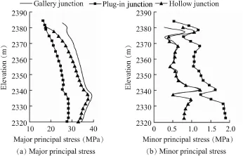
Fig.9.Distribution of principal stresses of cut-off wall along depth under different connections between cut-off wall and clay core.
4.Conclusions
In this paper,numerical analysis of a core rockfill dam built on a thick overburden deposit was conducted,and the effects of some factors on the stress-strain behavior of the cut-off wall were studied.The main conclusions are as follows:
(1)There is uneven settlement between the cut-off wall and the foundation,resulting in friction between the cut-off wall and the surrounding foundation.With the improvement of the overburden layer near the surface of the dam foundation,this uneven settlement and frictional force are effectively reduced, and the compressive stress of the cut-off wall along the depth is decreased by about 5—10 MPa.
(2)The frictional force between the cut-off wall and its surrounding soils should be considered in the simulation of the stress-strain behavior of the cut-off wall to ensure the accuracy of the stress in the cut-off wall,and both the Goodman element and mud-layer element are suitable for simulating the interfacial contact.
(3)With the decrease of the elastic modulus of concrete, the uneven settlement and f i ctional force between the cut-off wall and its surrounding soils decrease,resulting in the reduction of the compressive stress in the cut-off wall. Therefore,the low-modulus concrete whose stiffness is close to the foundation's stiffness is recommended for use in the construction of the cut-off wall,if the compressive strength of concrete is large enough to prevent crushing.
(4)The compressive stress of the cut-off wall changes signif i cantly when different connections between the cut-off wall and the clay core are used.Compared with the gallery junction,the plug-in junction can effectively reduce the compressive stress of the cut-off wall along the depth,and the hollow junction can reduce the compressive stress near the upper bottom side of the cut-off wall.
Acknowledgements
We would like to express our appreciation to Yue-min Zhang and Wen Long at Beijing Guardian Water Power Engineering Co.,Ltd.for giving some important suggestions for this paper.
Bao,C.G.,2007.Bao Chenggang Selected Papers on Study of Geotechnical Engineering.Changjiang Press,Wuhan(in Chinese).
Chen,G.,Ma,G.W.,Fu,X.Y.,Li,J.L.,Chen,J.Y.,2005.Research for the joint type by gallery between dam imperious wall and clay core of Pubugou Project.J.Sichuan Univ.37(5),32—36(in Chinese).
Cheng,Z.L.,2004.Strain status of vertical impervious wall in TGP stage-2 upstream cofferdam.J.Yangtze River Sci.Res.Inst.21(6),31—37(in Chinese).
Ding,Y.H.,Zhang,Q.G.,Zhang,B.Y.,2013.FEM analysis of stressdeformation characteristics of cut-off walls in high core rockfill dam.J. Hydroelectr.Eng.32(3),162—167(in Chinese).
Duncan,J.M.,Chang,C.Y.,1970.Non-linear analysis of stress and strain in soils.J.Soil Mech.Found.Div.96(5),1629—1653.
Gao,Z.P.,2000.Cutoff Wall of the Dam.China Electric Power Press,Beijing (in Chinese).
Goodman,R.E.,Taylor,R.L.,Brekke,T.L.,1968.A model for the mechanics of jointed rock.J.Soil Mech.Found.Div.94(3),637—659.
Jia,H.,He,S.B.,Wu,X.Y.,Zhu,J.G.,2008.Stress deformation analysis for the cutoff wall in foundation of Changheba core-rockfill dam.J.Water Resour.Water Eng.19(3),72—75(in Chinese).
Li,N.H.,Mi,Z.K.,Sun,D.W.,2007.Study on affecting factors of stressdeformation of diaphragm walls for concrete face rockfill dams built on thickalluviumdeposit.Chin.J.GeotechnicalEng.29(1),26—31(inChinese).
Li,Q.Y.,Cheng,Z.L.,2005.Analysis of the behaviour of stage II cofferdam of TGP.Chin.J.Geotechnical Eng.27(4),410—413(in Chinese).
Liu,S.H.,2008.Research on the Visible Finite Element Code for Rockfill Dam.Hohai University,Nanjing(in Chinese).
Lu,T.H.,Wang,R.D.,1998.Stress and deformation of concrete cut-off wall in Pubugou Earth-Rockfill Dam.J.Hohai Univ.(Nat.Sci.)26(2),41—44(in Chinese).
Pan,Y.,He,Y.L.,Zhou,X.X.,Cao,X.X.,2013.Analysis of effect of canyon terrain on stress and displacement of cutoff wall in dam foundation with deep overburden.Rock Soil Mech.34(7),2023—2030(in Chinese).
Wang,G.,Zhang,J.M.,Pu,J.L.,2006.An evaluation of the factors inf l uencing the stress and deformation of concrete diaphragm wall in dams.China Civ. Eng.J.39(4),73—77(in Chinese).
Xiang,D.R.,Shao,S.G.,Liu,S.H.,Zhu,J.G.,1991.3D Finite Element Code TDAD for Rockfill Dam.Beijing Science and Technology Press,Beijing (in Chinese).
Zhang,X.P.,Bao,C.G.,Zhang,J.S.,2000.The displacement and operation of impervious cores in phase-II cofferdam of Three Gorges Project.J.Hydraulic Eng.31(9),91—96(in Chinese).
Received 12 September 2015;accepted 16 January 2016
This work was supported by the National Natural Science Foundation of China(Grant No.51379066),the Fundamental Research Funds for the Central Universities(Grant No.2016B03514),the National Key Technology Support Program(Grant No.2015BAB07B05),and the Key Laboratory of Earth-Rock Dam Failure Mechanism and Safety Control Techniques(Grant No.YK913007).
*Corresponding author.
E-mail address:15850514642@163.com(Liu-jiang Wang).
Peer review under responsibility of Hohai University.
http://dx.doi.org/10.1016/j.wse.2016.11.002
1674-2370/©2016 Hohai University.Production and hosting by Elsevier B.V.This is an open access article under the CC BY-NC-ND license(http:// creativecommons.org/licenses/by-nc-nd/4.0/).
©2016 Hohai University.Production and hosting by Elsevier B.V.This is an open access article under the CC BY-NC-ND license(http:// creativecommons.org/licenses/by-nc-nd/4.0/).
杂志排行

Water Science and Engineering的其它文章
- Numerical analysis of rapid drawdown:Applications in real cases
- Stability analysis of unsaturated soil slope during rainfall inf i ltration using coupled liquid-gas-solid three-phase model
- Seismic responses of high concrete face rockfill dams:A case study
- Numerical simulation of seismic damage and cracking of concrete slabs of high concrete face rockfill dams
- Design considerations and behavior of reinforced concrete core dams during construction and impounding
- Calibration and performance of two different constitutive models for rockfill materials