Numerical analysis of rapid drawdown:Applications in real cases
2016-04-18NuriaPinyolb
*,Nu´ria M.Pinyolb
aDepartment of Civil and Environmental Engineering,Universitat Politˋecnica de Catalunya(UPC),Barcelona 08034,Spain
bCentre Internacional de Metodes Numerics en Enginyeria(CIMNE),Barcelona 08034,Spain
Numerical analysis of rapid drawdown:Applications in real cases
Eduardo E.Alonsoa,*,Nu´ria M.Pinyola,b
aDepartment of Civil and Environmental Engineering,Universitat Politˋecnica de Catalunya(UPC),Barcelona 08034,Spain
bCentre Internacional de Metodes Numerics en Enginyeria(CIMNE),Barcelona 08034,Spain
Available online 10 November 2016
In this study,rapid drawdown scenarios were analyzed by means of numerical examples as well as modeling of real cases with in situ measurements.The aim of the study was to evaluate different approaches available for calculating pore water pressure distributions during and after a drawdown.To do that,a single slope subjected to a drawdown was first analyzed under different calculation alternatives,and numerical results were discussed.Simple methods,such as undrained analysis and pure flow analysis,implicitly assuming a rigid soil skeleton,lead to signif i cant errors in pore water pressure distributions when compared with coupled flow-deformation analysis.A similar analysis was performed for the upstream slope of the Glen Shira Dam,Scotland,and numerical results were compared with field measurements during a controlled drawdown.Field records indicate that classical undrained calculations are conservative but unrealistic.Then,a recent case of a major landslide triggered by a rapid drawdown in a reservoir was interpreted.A key aspect of the case was the correct characterization of permeability of a representative soil prof i le.This was achieved by combining laboratory test results and a back analysis of pore water pressure time records during a period of reservoir water level f l uctuations.The results highlight the diff i culty of predicting whether the pore water pressure is overestimated or underestimated when using simplified approaches,and it is concluded that predicting the pore water pressure distribution in a slope after a rapid drawdown requires a coupled flow-deformation analysis in saturated and unsaturated porous media.
Hydro-mechanical coupling;Coupled flow-deformation analysis;Numerical analysis;Drawdown;Landslide;Pore water pressure
1.Introduction
Drawdown may be a critical factor in the stability of slopes that are initially partially or totally submerged.The reduction of water level has two effects:reduction of the stabilizing external hydrostatic pressure due to the unloading effect of removing water,and modif i cation of the internal pore water pressure.It is well known that if the drawdown velocity is too high,a delay is produced in the dissipation of pore water pressures inside the slope,and the remaining excess pore water pressures may induce a slope failure.The effects of water drawdown on the stability of slopes and dams have been reported from different perspectives based on laboratory tests (Yan et al.,2010;Wang et al.,2012),numerical analyses (Viratjandr and Michalowski,2006),and limit analyses(Gao et al.,2014).Previous research includes evaluation of the effect of the hydraulic properties through solution of the uncoupled-flow problem(Song et al.,2015),investigation of the inf l uence of drawdown on slope stability using a flow program for calculation of transient seepage and a coupled program for deformation and stability analysis(Berilgen, 2007),presentation of coupled flow-deformation analysis (Brinkgreve et al.,2015),and analysis of real cases(Zhang et al.,2010;Li et al.,2010).In addition,examples of drawdown-induced failures can be found in Sherard et al. (1963)and Lawrence Von Thun(1985).
The estimation of pore water pressure distributions due to a drawdown is therefore an important factor in analysis of the slope stability.Historically,two approaches to predicting the pore water pressure regime after a drawdown have beendeveloped:undrained analysis and the flow method.The first has been applied to the case of relatively impervious soil slopes,in which pore water pressures do not dissipate during drawdown events.Therefore,only the effect of the change in the total stress against the slopes is incorporated in the calculation.Early descriptions of this approach were published by Skempton(1954)and Morgenstern(1963),and more recent descriptions have been published by Lane and Griff i ths(2000) and Vandenberge(2014).The second approach involves the calculation of drawdown-induced pore water pressures by means of solving the flow problem caused by a change in hydraulic boundary conditions.This method implicitly assumes that the soil skeleton is rigid.Therefore,it does not consider any modif i cation of the initial pore water pressure induced by the change in the total boundary stress.In addition, as long as no mechanical equations are solved in this approach, no effects of soil deformation during drainage are included. Methods developed to handle this problem include flow net analysis(Reinius,1955;Cedergren,1967);methods based on an ad hoc hypothesis(typically Dupuit-type assumptions) (Brahma and Harr,1962;Stephenson,1978);finite element analysis of flow in saturated soil,which requires calculation of the position of the free surface(Desai,1977;Cividini and Gioda,1984);and finite element analysis of saturated and unsaturated flow(Neumann,1973;Pauls et al.,1999).
In practice,neither of these approaches can reliably approximate the situation in the field,because natural and compacted soils do not behave in a rigid or undrained manner. A coupled flow-deformation analysis should be used to obtain a drawdown-induced pore water pressure distribution.A generalformulation has been applied in thisanalysis, including equilibrium equations and balance equations of fluid and gas,to solve the drawdown problem in a coupled way. However,when only the flow problem is solved,but the mechanical equations are not considered,we refer to this case as uncoupled analysis,in which soil is assumed to be rigid.The undrained case is solved by means of the fully coupled formulation without allowing water flow.
The drawdown in a single slope is discussed first in this paper,to highlight the convenience of using a coupled flowdeformation approach.Then,a controlled drawdown event carried out at the Glen Shira Dam,Scotland,is presented.This case allows the validation of the computational results through comparison with field measurements.Finally,the paper also describes an incipient landslide located in the left margin of the Canelles Reservoir.The landslide was triggered by a reservoir drawdown.A hydro-mechanical analysis of a representative cross-section consistent with the available data is presented.
All the analyses presented were conducted with the finite element program Code_Bright.A theoretical description of this code is given in Olivella et al.(1996).The code was developed based on the finite element method for analysis of thermo-hydro-mechanical problems in geological media.The code deals with the deformable porous media as a mixture of three phases(solid,liquid,and gas).Solid corresponds to minerals,and liquid and gas correspond to water and dry air fi lling the pores,respectively.The theoretical approach consists of a set of governing equations,including a momentum balance equation,a mass balance equation,and constitutive laws.The latter describe thermal and hydraulic convective and advective flows,density changes of the components due to changes in stress and temperature,capillarity pressure evolution,and the constitutive mechanical response of the porous media.Several constitutive models are currently implemented. In this study,two models were used to simulate the soil response.A linear elastic model that requires two parameters (Young's modulus and Poisson's ratio)was selected as a simple model to analyze the effect of the mechanical response on the pore water pressure evolution in slopes subjected to a drawdown.A more complex constitutive model was used when evaluating the effect of the elastoplastic behavior observed in soils.The Barcelona basic model(BBM)presented by Alonso et al.(1990)was selected as a proper constitutive model for simulating the soil response in saturation and unsaturation conditions.It is a critical state model def i ned in terms of the net stress(the total stress in excess of the air pressure)and suction(the difference between the pore water pressure and air pressure),which can simulate the dependence of the stiffness and strength on suction and collapse(the soil deformation at a constant stress due to the reduction in suction).
2.Drawdown-induced pore water pressure in simple slope
Fig.1 shows the geometry of a single slope analyzed in this section.The slope,initially fully submerged,experiences a drawdown of the water level(50 m).The f i gure also indicates the positions of two singular points PAand PB,discussed below.
An elastic constitutive law was used to characterize the soil. Concerning the hydraulic description,the retention curve was def i ned by means of the Van Genuchten(1980)model.In the model,the parameters P0and Λ control the air entry value and the shape of the retention curve,respectively,and had assigned values of P0=0.30 MPa and Λ=0.33 in this study.The maximum and minimum degrees of saturation Srmaxand Srminwere assumed to be Srmax=1 and Srmin=0,respectively.The relative permeability(krel)varied with the degree of saturation (Sr),following a cubic law(krel=ksatS3r).A constant saturated permeability,ksat,with the value of 10-10m/s,was used in all the calculations.This is a low value,typical of an impervious material in engineering applications.
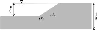
Fig.1.Geometry of slope.
The pore water pressure in the initial state was considered to be hydrostatic,determined by the maximum water level at the top of the slope.The case of an instantaneous drawdown wasconsidered first.If the soil is assumed to be rigid,the change in thetotalstressinducedbythedrawdownwillproducenochange inthevolumeofvoidsandsubsequentlyinporewaterpressures. In contrast,in a coupled analysis,the pore water pressure changes with the stress-strain behavior of the soil skeleton.In the present study,several elastic moduli of soil were considered (E=10000 MPa,1000 MPa,and 100 MPa).The first case correspondedtoastiffmaterial(asoftclayeyrock,forinstance). The second casewas an upper limit for a veryrigid,compacted, and low porosity material.The third case was a reasonable assumption for a well-compacted well-graded soil.
Fig.2 shows the calculated evolution of pore water pressures after the instantaneous drawdown at point PB.In the case of a rigid soil,no immediate effect of the drawdown occurs,as expected.In the coupled analysis,the instantaneous pore water pressure drops in relation to the compressibility of the soil skeleton.
The stiffer the soil is,the more limited the stress induced change in the pore water pressure will be.Immediately after the drawdown,a dissipation process begins.The rate of pore water pressure dissipation is controlled not only by the initial conditions after the drawdown,but also by the permeability and stiffness of the soil.In an uncoupled analysis,the calculated dissipation rates are higher,because of the implicit assumption of an infinitely rigid soil.Eventually,all cases result in the same long term solution.
The coupled analysis leads systematically to lower pore water pressures than the uncoupled(pure flow)analysis during the initial stage of dissipation.This is due to the effect of the initial state after the drawdown,controlled by the change in stress.However,since pore water pressures dissipate faster for a stiffer soil,this situation changes after some time,and pore water pressures recorded may also cross at some particular time,depending on the position of the point in the slope.Note also that a complete steady state is not reached at the end of the simulation period in this study.
A realisticcondition concerning thedrawdown rate (v=0.5 m/d)can be imposed.During the drawdown, boundary conditions of the upstream slope follow a seepage face condition:the boundary is assumed to be impervious unless the calculated pore water pressure at the boundary becomes positive.In this case water flows out of the slope under a seepage face condition.Three elastic moduli spanning the range of 100—10000 MPa were considered in this study.A low value for the saturated permeability was adopted so that the differences between coupled and uncoupled analyses could be highlighted.Of course,these differences decrease as the soil becomes more pervious.
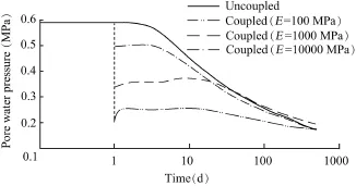
Fig.2.Pore water pressure evolution after instantaneous drawdown at point PB.
At point PA,all the coupled analyses led essentially to the same response.This is because variations in the instantaneous response were erased by the simultaneous dissipation of pore water pressures.For the stiffer materials with E=1000 MPa and 10000 MPa,pore water pressures remained slightly higher than the values of common soils that generally exhibit more compressibility.However,the pure flow analysis was far from the correct answer.
It may be argued that the pure flow analysis is a conservative approach in terms of slope safety against failure. However,this result depends on the particular case considered and cannot be generalized.It is important to note that the unrealistic uncoupled analysis leads to a lower pore pressure prediction in the long term.This is a result of the implicit assumption of infinite skeleton stiffness in the uncoupled calculation,leading to higher dissipation rates than the coupled analysis.
3.Glen Shira Dam
The Glen Shira Dam is a 16 m-high dam with a centered thin reinforced concrete wall.The embankment is mainly made of compacted well-graded non-plastic moraines.A rockfill shell covers the upstream slope of compacted moraines to increase the stability of the upstream shoulder.A detailed description of the dam and its materials is provided in Paton and Semple(1961).The maximum cross-section of the Glen Shira Dam is shown in Fig.3.
The dam was expected to experience fast drawdown rates because the reservoir operated following a pumping storage scheme.In order to evaluate the pore water pressure distribution inside the upstream shell,f i ve porous stone disks installed with piezometers were placed as shown in Fig.3.
Several calculations under saturation and unsaturation conditions were performed with the following hypotheses: Case 1,a pure flow analysis,in which the soils were considered rigid;Case 2,an instantaneous drawdown at the maximum intensity,followed by pore water pressure dissipation,with the soils simulated as elastic materials;Case 3,a coupled analysis,in which the soils were considered elastic; and Case 4,a coupled analysis,in which the soils were considered elastoplastic following the BBM model(Alonso et al.,1990).The parameters used for modeling were estimated according to Paton and Semple(1961),as shown in Table 1.
The Glen Shira Dam is especially interesting because the permeability of the compacted moraine(around 10-8m/s)is an intermediate value between those of the impervious clay and a free-draining material.One may wonder to what extent the classical hypothesis for drawdown analysis(undrained analysis or pure flow analysis)approximates the actual behavior.This will be discussed later.
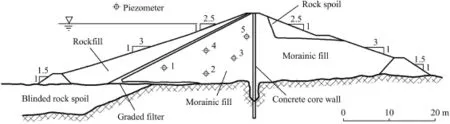
Fig.3.Maximum cross-section of Glen Shira Dam(Paton and Semple,1961).
The modeling of dam construction was conducted in simple steps.The initial conditions def i ned by the initial preconsolidation mean stressand initial suction(s0)are given in Table 1.
Fig.4 shows a comparison between the calculated evolution of pore water pressures and corresponding measurements of three piezometers,with the pore water pressure given in terms of the water head above the riverbed elevation.
Results of Case 3 show satisfactory agreement with measurements.The pattern of recorded pore water pressures and the smoothing effect induced by the soil stiffness and permeability are well captured by the model.Better agreement between measurements and calculations probably requires the consideration of certain field heterogeneity in permeability and/or soil stiffness.
We also compared the performance of the different analysis methods listed above.Considering first the hypothesis of an instantaneous drawdown in Case 2,the calculated pressure drop is indicated in Fig.4 by means of a vertical bar.A (coupled)dissipation process was calculated,and the progressive decay in pore water pressures was also plotted.If compared with the actual pore water pressures measured at the end of the real drawdown period,the hypothesis of an instantaneous drawdown leads to an extremely conservative and unrealistic situation in piezometer 2.
Considering now the opposite calculation method,the pure flow analysis in Case 1,Fig.4 indicates that the predicted pore pressures are lowest if compared with the remaining analysis methods.Calculated pore water pressures closely follow the variation of the reservoir water level.The damping effect associated with the soil compressibility is absent.When the water level increases at the end of the drawdown test,the pure flow analysis indicates,against the observed behavior,a fast recovery of pore water pressures within the embankment.
The elastoplastic effect can be evaluated through comparison of cases 3 and 4.The difference in terms of the pore water pressure evolution is not signif i cant.This result can be explained if the stress paths during construction,reservoir impoundment,and drawdown are analyzed.The loading applied during construction due to the weight of compacted layers determines the size of the yield surface.Once the dam construction is completed,reservoir impoundment leads to a reversal of the stress path,which enters the elastic zone.A drawdown leads to a new sharp reversal of the stress path and an increase of deviatoric stresses.However,at the end of the drawdown,the stress path may remain inside the elastic locus. The possibility of inducing additional plastic strain during the drawdown depends on the geometry of the dam cross-section and the constitutive behavior of the materials involved.The Glen Shira Dam has stable geometry because of the low upstream slope and relatively low shear stresses inside the dam. In addition,the granular shell material has a high friction angle of 35。and a relatively high elastic stiffness.These factors lead to insignif i cant plastic strains during the drawdown.However, under different circumstances,the plastic strain may develop during a drawdown,affecting the change of pore water pressures.
4.Canelles landslide
The Canelles landslide was described in more detail in Pinyol et al.(2012).During a long period of time(more than 10 years),the Canelles Reservoir(Spain)was maintained at a high water level.Fig.5 shows the time evolution of thereservoir water level.For the sake of reference,the maximum water level is 505 m.Due to a dry period,the reservoir water level decreased in 2005 and reached an absolute minimum value of 426 m in the summer of 2006.At that time a 2 kmlong tension crack was observed in the left margin of the reservoir.Subsequent geological and geotechnical investigation led to a conclusion that a preexisting landslide had been reactivated and a volume of mass around 40×106m3had been mobilized.

Table 1Model parameters used for analysis of Glen Shira Dam.

Fig.4.Comparison of measured pore water pressures obtained from different piezometers and calculated results in different cases.
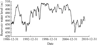
Fig.5.Water level variation in Canelles Reservoir.
A representative geological cross-section of the slope is shown in Fig.6.A siltstone and limestone stratum(40 m thick) and a limestone stratum(15—25 m thick)are above a thin Garumnian claystone stratum(1—2 m thick).Below this clayey stratum,a massive sandstone stratum(35—55 m thick) provides the lower limit for the slide.
The landslide occurred within a sequence of sedimentary rocks.The sliding surface was determined based on a detailed analysis of continuous cores recovered in deep borings and limited information provided by inclinometers installed at the beginning of 2007.The development of the sliding surface follows a large syncline structure inside the continuous and relatively thin and weak claystone layer.The position of the sliding surface is also indicated in Fig.6.
The properties of the clayey soil where the failure surface was located were investigated in the laboratory using natural and remoulded samples,of which the liquid limit wLranged from 54%to 57%,and the plasticity index PI ranged from 26% to 31%.Since the landslide was a reactivated slide,the residual strength was measured with the ring shear equipment.The residual friction angle at the sliding surface was determined to be 12。—13。for the normal effective stress of 100—250 kPa.The sliding surface was often located at depths of 50—100 m,and therefore,normal effective stresses prevailing in situ were substantially higher(800 kPa in average)than those in the testing range.In addition,previous normal stresses,both of lithostatic and tectonic origins,might have also reached higher valuesthanpresentvalues.Therefore,theinsitufrictionangleat the failure surface was probably smaller than the values measured in the laboratory,and thus,a likely in situ value was estimated to be 10。—12。(Stark and Eid,1997;Alonso,2005). The permeability of the clayey soil was also measured: k=4.2×10⁻¹⁰m/sand4.9×10-11m/sforthetwoundisturbed specimens.Thissetofresultsguidedtheselectionofparameters in the following analysis.
The causes of the landslide development were investigated. Vibrating wire piezometers used for measuring the pore water pressure were installed at the positions of borings in November 2007,indicated in Fig.6,with three or four sensors installed in each boring in the vicinity of the sliding surface.Three sensors of a piezometer were installed at the elevations of 410,420, and 430 m,respectively,in the boring SI 2-2;two of them were located in the lower sandstone stratum,and one in the clayey stratum.Fig.7 shows the piezometric measurements at the boring SI 2-2 and the reservoir water level.
The examination of all piezometric measurements leads to the following conclusions:(1)the hydraulic behavior of the Garumnian claystone stratum seems to be independent of the lower sandstone stratum;(2)the pore water pressure in the sandstone stratum,except for the upper part of the slide, immediately follows the water level variation in the reservoir, which is an indication of high permeability of sandstones;and (3)the pore water pressure remains essentially constant in the clayey stratum,independent of the water level variation duringthe first seven months of measurements when the reservoir water level is lower than 460 m,indicating the diff i culty of dissipating or increasing the pore water pressure within the clayey stratum where the sliding surface is located,which also demonstrates the low in situ permeability of the clayey stratum.

Fig.6.Geological cross-section of Canelles landslide.
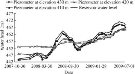
Fig.7.Piezometer records at boring SI 2-2 and reservoir water level.
The pore water pressure distribution in the slope was calculated by means of Code_Bright.The representative section shown in Fig.6 was reproduced.In order to simplify the model,the actual sequence of stratif i cation above the clayey stratum was not distinguished in detail.The mobilized zone was characterized as a unique material.
The constitutive behavior of the materials was characterized by means of a linear elastic law.This simplif i cation is assumed to be acceptable,when taking into account the limited elastoplastic effect on the drawdown-induced pore water pressure,as discussed above.
Table 2 indicates the parameters introduced for calculation. The compressibility and permeability of the clayey soil were def i ned according to the laboratory results.The rest of the parameters were estimated according to typical values due to the lack of data.
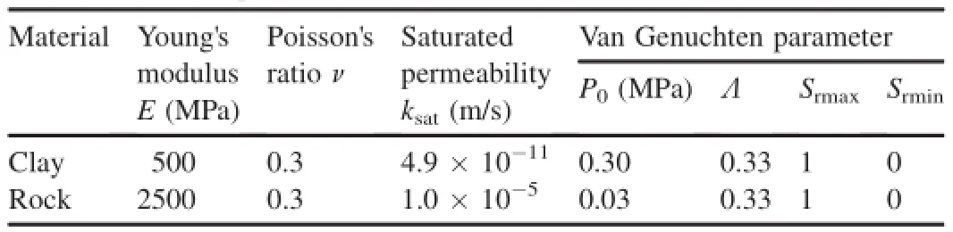
Table 2Parameters for coupled hydro-mechanical calculations.
The change of reservoir water level was simulated with the coupled hydro-mechanical model from September 2002 to January 2010.The effect of rainfall was incorporated into the model for simulating water inflow corresponding to the mean annual precipitation of 400 mm in the region.
Fig.8 shows the comparison between measurements of a piezometer in the boring SI 2-2 and simulated results.Pore water pressures measured within the lower sandstone stratum, which precisely follow the water level variation,are captured by the calculation.This is a consequence of correctly choosing the permeability of sandstones.Pressure measurements at the boring SI 2-2 within the impervious clayey stratum,which are especially important for the subsequent calculation of the safety factor,have been simulated quite satisfactorily.Pressures are lightly overestimated at the low reservoir water level.
The same model was used to calculate the pore water pressure distribution in 2006 when the reservoir water level reached a minimum value.The pore water pressure distribution was later used to calculate the safety factor by means of the limitequilibrium procedure (the Morgenstern-Price method).Two critical drawdown events on September 26, 2005 and August 21,2006 were analyzed.The safety factors obtained for a friction angle equal to 10。were very close to 1 (1.04 and 1.09,respectively).These values indicate that the two drawdown events were quite critical with regard to the stability of the slide.Although both safety factors were higher than 1,a failure was observed.This discrepancy can be explained when taking into account the fact that piezometricmeasurements(at the boring SI 2-3)indicated higher pore water pressure values in the upper part of the landslide,which could not be reproduced by the hydro-mechanical model. These higher values were probably a consequence of the groundwater inflow or runoff from the upslope,not included in the model.Despite this minor discrepancy,it is concluded that the failure was a result of the rapid drawdown and the low reservoir water level in the summer of 2006.
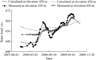
Fig.8.Comparison of calculated and measured pore water pressures by piezometer at two elevations in boring SI 2-2.
5.Conclusions
The stability of slopes and earth dams may be precarious when subjected to a drawdown.The assessment of slope stability under different initial conditions andwater level evolution in time requires predicting the pore water pressure evolution in the slope.The discussion presented in the paper,based on a homogeneous slope,demonstratesthatsimple analysis, assuming undrained behavior or pure flow(without taking into account soil deformation),leads to erroneous solutions in terms of the porewater pressure distribution.It is notpossible to know which one of the two simplified analyses is a conservative approach,in terms of slope stability against failure.
A coupled flow-deformation procedure is presented as an appropriate approach to handling the drawdown scenario in a consistent manner.Two real cases affected by a drawdown were analyzed in this study using a coupled hydro-mechanical fi nite element code.A signi fi cant case is the behavior of the Glen Shira Dam when subjected to a controlled drawdown. The agreement between measurements and numerical results is quite strong when coupled effects are included.
ThecasestudyoftheGlenShiraDamshowsthattheclassical analysis methods fall far short of explaining the recorded behavior.The method of instantaneous drawdown or undrained analysis is conservative,but very unrealistic.At the opposite extreme,the pure flow analysis leads to a systematic and unsafe underestimation of pore water pressures during the drawdown. Coupled analysis captures the actual measurements well.In the case of the Glen Shira Dam,plastic strain during the drawdown was probably non-existent,and the simpler elastic approach providedagoodapproximationofrecordedporewaterpressures.
Another case is a large slope failure observed in the left margin of a reservoir.The failure was detected after a drawdown.After a geological and geotechnical investigation,the slope was modeled.Then,the evolution of the reservoir water level was simulated,and the effect of rainfall was incorporated into the model.Pore water pressure measurements were unavailable previous to the failure.However,piezometers were installed later,and measurements were used to validate the model.The calculated pore water pressure distribution after the drawdown can explain the failure observed.
Alonso,E.E.,Gens,A.,Josa,A.,1990.A constitutive model for partially saturated soils.Gˊeotechnique 40(3),405—430.http://dx.doi.org/10.1680/ geot.1990.40.3.405.
Alonso,E.E.,2005.Parˊametros de Resistencia en cˊalculos de estabilidad.In: Proceedings of the VI Simposio Nacional sobre Taludes y Laderas Inestables.Universidad Politˊecnica de Valencia and Universitat Politˋecnica de Catalunya,Valencia,pp.1131—1195.
Berilgen,M.M.,2007.Investigation of stability of slopes under drawdown conditions.Comput.Geotechnics 34(2),81—91.http://dx.doi.org/10.1016/ j.compgeo.2006.10.004.
Brahma,S.P.,Harr,M.E.,1962.Transient development of the free surface in a homogeneous earth dam.Gˊeotechnique 12(4),283—302.http://dx.doi.org/ 10.1680/geot.1962.12.4.283.
Brinkgreve,R.B.J.,Kumarswamy,S.,Swolfs,W.M.,2015.Plaxis 2015, Reference Manual.Plaxis BV,Delft.
Cedergren,H.R.,1967.Seepage,Drainage and Flow Nets.John Wiley and Sons Ltd.,New York.
Cividini,A.,Gioda,G.,1984.Approximate F.E.analysis of seepage with a free surface.Int.J.Numer.Anal.Methods Geomechanics 8(6),549—566. http://dx.doi.org/10.1002/nag.1610080605.
Desai,C.S.,1977.Drawdown analysis of slopes by numerical method.J.Soil Mech.Found.Div.103(7),667—676.
Gao,Y.,Zhu,D.,Zhang,F.,Lei,G.H.,Qin,H.,2014.Stability analysis of threedimensional slopes under water drawdown conditions.Can.Geotechnical J. 51(11),1355—1364.http://dx.doi.org/10.1139/cgj-2013-0448.
Lane,P.A.,Griff i ths,D.V.,2000.Assessment of stability of slopes under drawdown conditions.J.Geotechnical Geoenvironmental Eng. 126(5),443—450.http://dx.doi.org/10.1061/(ASCE)1090-0241(2000) 126:5(443).
Lawrence Von Thun,J.,1985.San Luis dam upstream slide.In:Proceedings of the 11th International Conference on Soil Mechanics and Foundation Engineering,vol.5.CRC Press,San Francisco,pp.2593—2598.
Li,D.Y.,Yin,K.L.,Leo,C.,2010.Analysis of Baishuihe landslide inf l uenced by the effects of reservoir water and rainfall.Environ.Earth.Sci.60(4), 677—687.http://dx.doi.org/10.1007/s12665-009-0206-2.
Morgenstern,N.R.,1963.Stability charts for earth slopes during rapid drawdown.Gˊeotechnique 13(2),121—131.http://dx.doi.org/10.1680/ geot.1963.13.2.121.
Neumann,S.P.,1973.Saturated-unsaturated seepage by finite elements.J. Hydraulic Div.99(12),2233—2250.
Olivella,S.,Gens,A.,Carrera,J.,Alonso,E.E.,1996.Numerical formulation for a simulator(CODE BRIGHT)for the coupled analysis of saline media.Eng.Comput.13(7),87—112.http://dx.doi.org/10.1108/ 02644409610151575.
Paton,J.,Semple,N.G.,1961.Investigation of the stability of an earth dam subjected to rapid drawdown including details of pore pressure recorded during a controlled drawdown test.In:Pore Pressure and Suction in Soils. Butterworths,London,pp.85—90.
Pauls,G.J.,Karlsauer,E.,Christiansen,E.A.,Wigder,R.A.,1999.A transient analysis of slope stability following drawdown after f l ooding of highly plastic clay.Can.Geotechnical J.36(6),1151—1171.http://dx.doi.org/ 10.1139/t99-073.
Pinyol,N.M.,Alonso,E.E.,Corominas,J.,Moya,J.,2012.Canelles landslide: Modelling rapid drawdown and potential sliding.Landslides 9(1),33—51. http://dx.doi.org/10.1007/s10346-011-0264-x.
Reinius,E.,1955.The stability of the slopes of earth dams.Gˊeotechnique 5(2), 181—189.http://dx.doi.org/10.1680/geot.1955.5.2.181.
Sherard,J.L.,Woodward,R.J.,Gizienski,S.F.,Clevenger,W.A.,1963.Earth and Earth-rock Dams.John Wiley and Sons,New York.
Skempton,A.W.,1954.The pore pressure coeff i cients A and B.Gˊeotechnique 4(4),143—147.http://dx.doi.org/10.1680/geot.1954.4.4.143.
Song,K.,Yan,E.,Zhang,G.,Lu,S.,Yi,Q.,2015.Effect of hydraulic properties of soil and f l uctuation velocity of reservoir water on landslide stability.Environ.Earth Sci.74(6),5319—5329.http://dx.doi.org/10.1007/ s12665-015-4541-1.
Stark,T.D.,Eid,H.T.,1997.Slope stability analyses in stiff f i ssured clays.J. Geotechnical Geoenvironmental Eng.123(4),335—343.http://dx.doi.org/ 10.1061/(ASCE)1090-0241(1997)123:4(335).
Stephenson,D.,1978.Drawdown in embankments.Gˊeotechnique 28(3), 273—280.http://dx.doi.org/10.1680/geot.1978.28.3.273.
Van Genuchten,M.T.,1980.A closed-form equation for predicting the hydraulic conductivity of unsaturated soils.Soil Sci.Soc.Am.J.44(5), 892—898.http://dx.doi.org/10.2136/sssaj1980.03615995004400050002x.
Vandenberge,D.R.,2014.Total stress rapid drawdown analysis of the Pilarcitos Dam failure using the finite element method.Front.Struct.Civ.Eng. 8(2),115—123.http://dx.doi.org/10.1007/s11709-014-0249-7.
Viratjandr,C.,Michalowski,R.L.,2006.Limit analysis of submerged slopes subjected to water drawdown.Can.Geotechnical J.43(8),802—814.http:// dx.doi.org/10.1139/t06-042.
Wang,J.J.,Zhang,H.P.,Zhang,L.,Liang,Y.,2012.Experimental study on heterogeneous slope responses to drawdown.Eng.Geol.147—148,52—56. http://dx.doi.org/10.1016/j.enggeo.2012.07.020.
Yan,Z.L.,Wang,J.J.,Chai,H.J.,2010.Inf l uence of water level f l uctuation on phreatic line in silty soil model slope.Eng.Geol.113(1—4),90—98.http:// dx.doi.org/10.1016/j.enggeo.2010.02.004.
Zhang,T.,Yan,E.,Cheng,J.,Zheng,Y.,2010.Mechanism of reservoir water in the deformation of Hefeng landslide.J.Earth.Sci.21(6),870—875. http://dx.doi.org/10.1007/s12583-010-0139-4.
Received 2 September 2015;accepted 12 June 2016
*Corresponding author.
E-mail address:eduardo.alonso@upc.edu(Eduardo E.Alonso).
Peer review under responsibility of Hohai University.
http://dx.doi.org/10.1016/j.wse.2016.11.003
1674-2370/©2016 Hohai University.Production and hosting by Elsevier B.V.This is an open access article under the CC BY-NC-ND license(http:// creativecommons.org/licenses/by-nc-nd/4.0/).
©2016 Hohai University.Production and hosting by Elsevier B.V.This is an open access article under the CC BY-NC-ND license(http:// creativecommons.org/licenses/by-nc-nd/4.0/).
杂志排行

Water Science and Engineering的其它文章
- Stability analysis of unsaturated soil slope during rainfall inf i ltration using coupled liquid-gas-solid three-phase model
- Seismic responses of high concrete face rockfill dams:A case study
- Numerical simulation of seismic damage and cracking of concrete slabs of high concrete face rockfill dams
- Design considerations and behavior of reinforced concrete core dams during construction and impounding
- Numerical stress-deformation analysis of cut-off wall in clay-core rockfill dam on thick overburden
- Calibration and performance of two different constitutive models for rockfill materials