Seismic responses of high concrete face rockfill dams:A case study
2016-04-18KuangmingWeiHuaqiangHan
*,Kuang-ming Wei,Hua-qiang Han
aGeotechnical Engineering Department,Nanjing Hydraulic Research Institute,Nanjing 210024,China
bKey Laboratory of Failure Mechanism and Safety Control Techniques of Earth-rock Dam,Ministry of Water Resources,Nanjing 210029,China
Seismic responses of high concrete face rockfill dams:A case study
Sheng-shui Chena,b,Zhong-zhi Fua,b,*,Kuang-ming Weia,b,Hua-qiang Hana,b
aGeotechnical Engineering Department,Nanjing Hydraulic Research Institute,Nanjing 210024,China
bKey Laboratory of Failure Mechanism and Safety Control Techniques of Earth-rock Dam,Ministry of Water Resources,Nanjing 210029,China
Available online 3 October 2016
Seismic responses of the Zipingpu concrete face rockfill dam were analyzed using the finite element method.The dynamic behavior of rockfill materials was modeled with a viscoelastic model and an empirical permanent strain model.The relevant parameters were obtained either by back analysis using the field observations or by reference to parameters of similar rockfill materials.The acceleration responses of the dam, the distribution of earthquake-induced settlement,and the gap propagation under the concrete slabs caused by the settlement of the dam were analyzed and compared with site investigations or relevant studies.The mechanism of failure of horizontal construction joints was also analyzed based on numerical results and site observations.Numerical results show that the input accelerations were considerably amplified near the top of the dam,and the strong shaking resulted in considerable settlement of the rockfill materials,with a maximum value exceeding 90 cm at the crest. As a result of the settlement of rockfill materials,the third-stage concrete slabs were separated from the cushion layer.The rotation of the cantilever slabs about the contacting regions,under the combined action of gravity and seismic inertial forces,led to the failure of the construction joints and tensile cracks appeared above the construction joints.The effectiveness and limitations of the so-called equivalent linear method are also discussed.
Concrete face rockfill dam(CFRD);Seismic response;Zipingpu;Permanent strain;Construction joint;Viscoelastic model;Finite element method
1.Introduction
Aconcretefacerockfilldam(CFRD)isatype ofdamwidely used in hydropower projects all around the world.Concrete slabs,supported and stabilized by the underlying rockfill materials,areconnectedwiththetoeplinthbytheperipheraljoints, so as to form an impermeable system.Due to the excellent adaptability of CFRDs to topographical and geological conditions and the signif i cant economic advantage of using local materials,CFRDs have become quite a competitive alternative toconcretedams.Theinventionandapplicationofthevibratory compaction method have further and advantageously enhanced the density and moduli of compacted rockfill materials and therefore successfully reduced the unfavorable deformation encountered in early hydraulic fill dams.As a result,the height ofmodernCFRDshasgrowncontinuouslyfrom100mto200m over the past f i fty years(ICOLD,2010).The highest CFRD in the world to date is the 233-m Shuibuya Dam located in Hubei Province,China(Zhou et al.,2011).China is now planning to face the challenge of constructing CFRDs with a height near or over 300 m.
Unfortunately,China is located between the circum-Pacif i c seismic belt and the Mediterranean-Himalayan seismic belt, and it has been frequently struck by large earthquakes throughout history.Moreover,large amounts of high CFRDs built,under construction,and under design in China are located in regions of high seismic intensity(Chen,2015).On May 12, 2008,anearthquakewithaRichtermagnitudeof8.0hitSichuanProvinceinwesternChina,andthewell-knownZipingpuCFRD (156 m),which is located about 17 km away from the epicenter, was severely damaged by the earthquake.Post-quake investigations at the dam site show that the dam settled considerablyatthecrestandsomeoftheconcreteslabsweredislocated along the horizontal construction joints due to the seismic excitation(Chen,2015;KongandZou,2014).Examinationand measurement also indicate that the concrete slabs near the dam crest were separated from the cushion layer and the peripheral jointsunderwentanobviousdisplacement(SongandCai,2009). In addition,the strong earthquake resulted in many visible tensile cracks and compressive failure within the concrete slabs and the parapet walls(Chen,2015).
Although the damage to the Zipingpu CFRD caused by the earthquake was severe,the dam survived the extremely strong earthquake and its functions were recovered after several months of rehabilitation.This rare case redemonstrated the high resistance of this type of dam to earthquakes and the feasibility of building high CFRDs in regions of high seismic intensity.Since the dam's rehabilitation,substantial attention has been paid to the seismic behavior of high dams,not only in order to deepen the understanding of their seismic behavior but also to improve the design and construction levels (Dakoulas,2012;Feng et al.,2010;Kong et al.,2012a;Xiong et al.,2013;Zhong et al.,2013).
The objective of this study was to investigate the seismic behavior of the Zipingpu CFRD through numerical simulations on the basis of the equivalent linear method.Special emphasis was placed on the amplif i cation coeff i cient of the base acceleration and the earthquake-induced settlement of the dam,as well as the gap propagation under the concrete slabs.The mechanism of failure of construction joints was also studied based on numerical analysis and field observations.Although the conclusions obtained from a single case study may not be generally applicable,the results presented in this paper may offerusefulinsightintotheseismicbehaviorofsimilarprojects.
2.Relevant information regarding Zipingpu CFRD
2.1.Dam materials and construction stages
The Zipingpu CFRD is located in Dujiangyan City,in Sichuan Province,China.The maximum height of the dam is 156 m and the length and width of the crest are 663.77 m and 12 m,respectively.Both the upstream and downstream slope ratios below an elevation of 840 m are 1:1.4 and the downstream slope ratio above this elevation is 1:1.5.Fig.1 shows the material zones of the dam(separated by the solid lines)and the three stages of construction(separated by the dashed lines).Excluding the cushion layer(IIA)and the transition layer(IIIA),the dam can be partitioned mainly into three different zones:IIIB,IIIC,and IIID in Fig.1.The mineral contents of rockfill,cushion,and transition materials are all limestone,but with different grain size distributions.The main rockfill(IIIB)and the secondary rockfill(IIIC)have the same origin and grain size distribution.However,the designed densities of both zones are slightly different:the IIIB zone and the IIIC zone were compacted to densities of 2.16 g/cm3and 2.15 g/cm3,respectively.
As shown in Fig.1,the dam materials were filled to an elevation of 810 m during the first construction stage,850 m in the second stage,and 884 m in the third stage.In accordance with the construction processes of the dam,concrete slabs (C25)were also cast in three stages.After the filling of dam materials to the designed elevations for the first and second stages,the concrete slabs were cast to elevations several meters below the existing dam crest.After the completion of the third stage,they were cast to an elevation of 879.4 m in order to connect them to the parapet walls.Therefore,two layers of construction joints exist within the face slabs at elevations of 796 m and 845 m.These construction joints are horizontal, and they proved to be vulnerable to dislocation during the Wenchuan earthquake(Song and Cai,2009).
2.2.Deformation monitoring system
Due to the signif i cance of the Zipingpu CFRD,a total of 56monitoringgaugeswereinstalledalongfourmonitoringlines in the 0+251.00 m section and three monitoring lines in the 0+371.00 m section so as to track the deformation behavior of the dam.Fig.2 shows the locations of the 34 monitoring instruments in the major monitoring section of 0+251.00 m. During the main shock and aftershocks of the Wenchuan earthquake,most of these monitoring gauges functioned effectively,andprovidedvaluabledataforthesafetyevaluationofthe dam.Although the dam was designed to withstand an earthquake with a seismic intensity of 8.0,and the peak bedrock acceleration with an exceedance probability of 0.02 within100 years was 259.6 cm/s2,the dam sustained the Wenchuan earthquake,which had a seismic intensityhigher than 9.0,and a peakbedrockaccelerationhigherthan5m/s2.Boththeobserved and unobserved responses of the dam during the earthquakes inspired the numerical investigations in this study,as will be described in the following sections.
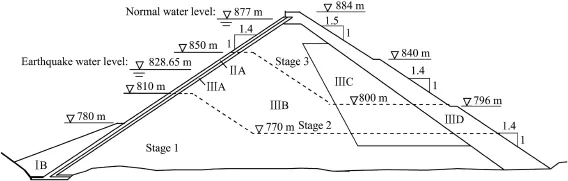
Fig.1.Typical cross-section of Zipingpu CFRD(0+321.00 m).

Fig.2.Settlement monitoring instruments in 0+251.00 m cross-section.
2.3.Finite element model of dam
The Zipingpu CFRD was discretized into 8601 solid elements,503 interface elements,and 531 joint elements.Fig.3 shows the three-dimensional mesh of the dam.The material zones and the construction processes were appropriately consideredinmeshing,andsuff i cientnodeswereassignedatthe locations of the monitoring gauges for the convenience of comparison.Inbothstaticanddynamicanalyses,thenodesatthe bottomboundaryofthedamwerefullyrestrictedfromdisplacing along three directions,and the nodes at the left and right abutments were only restricted from moving along the x axis.
3.Constitutive models and numerical issues
In this study,an equivalent linear dynamic analysis of the seismic response was performed.In particular,a viscoelastic model was used to model the energy dissipation behavior of the rockfill materials and an empirical residual strain model was employed to study the permanent deformation behavior. In this section,the relevant constitutive models and numerical issues are simply explained.

Fig.3.Three-dimensional finite element mesh of dam.
3.1.Viscoelastic model of rockfill materials
Based on large-scale dynamic triaxial experiments on rockfill materials,Shen(2000)suggested using the following equation to evaluate the equivalent shear modulus G:
where Gmaxis the maximum shear modulus at a very small normalized cyclic shear strain amplitudeand it can be calculated from

where p0and paare the mean effective stress prior to cyclic loading and the referential atmospheric pressure,respectively; k1,k2,and n1are three parameters;andis the normalized cyclic shear strain,which can be expressed as
The damping ratio λ is also a function of the magnitude of(Shen,2000),i.e.,

where λmaxis the maximum damping ratio that could be achieved while the cyclic shear strain approaches inf i nity→∞).
3.2.Permanent strain model of rockfill materials
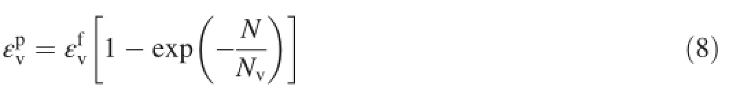
The permanent shear strain,γp,is a function of the cyclic shear strain amplitude and the number of the loading cycle,N, as follows(Chen,2015):

where

and
In Eqs.(6)and(7),γcis the cyclic shear strain amplitude, def i ned as the numerator of Eq.(3);cγ,αγ,dγ,and βγare four parameters for the permanent shear strain;and η0denotes the initial stress ratio def i ned aswhere q0is the generalized shear stress,and s0ij(i,j=1,2,3) is the deviator of the static(initial)stress tensor.
The evolution of permanent volumetric straincan be satisfactorily modeled with the following exponential function (Chen,2015):
where

and

In Eqs.(9)and(10),cv,αv,dv,and βvare four parameters for the permanent volumetric strain.
3.3.Equivalent loading cycles of an irregular process
The number of loading cycles N has been introduced as an independent variable in equations for permanent strains. However,the stress histories of rockfill materials(σc)within a dam are quite complex and absolutely irregular.Thus,a rule is required to translate an irregular process into a regular one. Based on an assumption that the energy dissipated during an irregular stress history is identical to that dissipated during the equivalent regular one,the following equation is suggested by the authors(Fu et al.,2015):

In this equation,εcis the cyclic strain tensor,and the numerator is the energy dissipated within a given element during the relevant stage.The denominator is the energy that will be dissipated by this element if it is subjected to a regular shear cycle with the equivalent average shear stain amplitude,which can be empirically evaluated as a fraction of the maximum shear strain,,as suggested by Idriss and Sun (1992)in the SHAKE91 program:

Generally,Rγis a constant that depends on the magnitude of the earthquake.Hereafter,it is assumed to be 0.65.
3.4.Plastic flow rule determining strain components
The empirical formulas established above for the permanent strains are of vital importance in predicting the permanent deformation of rockfill dams.However,translating the permanent strains(εp)to a deformation field is not straightforward.Within the framework of the finite element method,the easiest way is probably to translate the potential permanent strains into nodal forces,F,using the following equation:

where V is the elementary volume;the matrix B in the finite element method is used to translate a nodal displacement vector to a strain vector;σpis the relaxed stress tensor in the case that the boundary of elements is restricted so that permanent strains are not allowed to occur;and D0is the elastic or elastoplastic matrix,which can be established based on the static constitutive model and the corresponding parameters.
Use of Eq.(13)also requires the permanent strain components.This is in essence a problem of choosing a plastic flow rule.Considering the fact,evidenced from both site investigation and centrifuge model tests(Wang and Zhang, 2003),that the permanent deformation of CFRDs is strongly in fl uenced by the static stress state prior to earthquake shaking,we adopt the following flow rule:

A finite element procedure,the Dynamic Response Analysis Program for Earth and Rockfill Structures(DRAPERS), incorporating the models described above was developed and used in this study.DRAPERS has already been used in evaluating the seismic behavior of several high earth and rockfill dams,and it has been proven a convenient and reliable program(Fu et al.,2015).
4.Model parameters and base excitations
4.1.Static model parameters
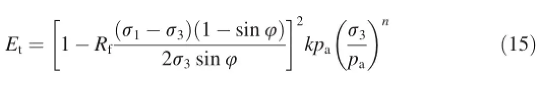
To launch the dynamic response analysis,the initial stress and strain states within the finite element model should be determined.Therefore,static analysis was conducted prior to the dynamic analysis.In this study,the double-yield-surface model proposed by Shen(2000)was employed.In this model,the tangential modulus(Et)and the elastic modulus (Ee)of elements are calculated with the following equations:
and

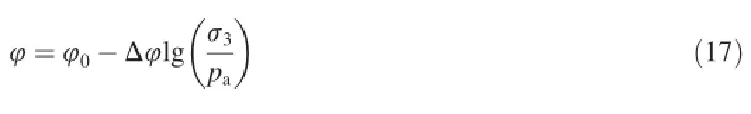
where σ1and σ3are the maximum and the minimum principal stresses,respectively.Rf,k,kur,and n are four parameters.The peak frictional angle(φ)depends on the minimum principal stress as follows:
The volumetric behavior in Shen's model was revised using the following stress-dilatancy equation(Fu et al.,2014):
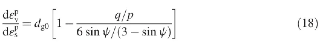
where ψ0and Δψ are two dilation parameters.
The model parameters were back-analyzed using the observed deformation data.Table 1 lists the calibrated parameters,where ν is the elastic Poisson's ratio.Note that a single group of parameters was used for IIIB,IIIC,and IIID zones since they have the same origin and grading,although slightly different compaction criteria.
For concrete slabs and toe plinth,the isotropic elastic model was used,i.e.,Ee=28 GPa and ν=0.167,throughout the static and dynamic analysis.The interface behavior between the concrete slabs and the cushion layer was modeled with a zero-thickness model proposed by Goodman et al. (1968),and the parameters used were Rf=0.86,k=5600, n=0.5,and φ=36.0。.The joint behavior between different slabs and the plinth was modeled using the parameters summarized by Gu et al.(2009).
Fig.4 compares the numerical and observed distributions of the settlement,after the cast of the third-stage concrete slabs, in the 0+251.00 m and 0+371.00 m sections.The magnitude of the settlement is indicated by the vertical distance between the initial horizontal lines and their displaced counterparts, represented by the solid and dashed curves.At all the monitored elevations,the numerical results agree with the observed data,which proves the credibility of the constitutive model weused and the relevant parameters.Since the deformation behavior prior to reservoir impounding is reliable,the initial stress and strain states before the earthquake obtained through fi nite element simulation can also represent the initial state of the dam satisfactorily.

Table 1Calibrated parameters of Shen's double-yield-surface model.

Fig.4.Comparison of calculated and observed settlements in two sections.
4.2.Dynamic model parameters
㉝爱新觉罗·弘历:《平湖秋月》,齐耀珊重修、吴庆坻重纂:《民国杭州府志》(一),《中国地方志集成·浙江府县志辑》第1册,第46页。
The model parameters used in the dynamic analysis were not calibrated based on experiments on rockfill materials used in the Zipingpu CFRD,since it is impossible to quarry the rockfill materials from the dam.However,we have conducted dynamic experiments on many kinds of rockfill materials used in more than 60 rockfill dams over the past decades.After a thorough review of the database,we found that the physical and mechanical behavior of the rockfill materials in the Zipingpu CFRD(IIIB and IIIC)is similar to what is observed in the weathered sandstone material used in the Cihaxia CFRD,located in Qinghai Province(Fu and Ling,2009),as listed in Table 2.Table 3 provides the dynamic model parameters of the tested materials,which were used in the seismic response analysis described in the following section.
4.3.Base excitation
There are in total six strong motion seismographs installed on the dam,three at the crest(at an elevation of 884 m)and three on the downstream slope(at elevations of 840 m,796 m, and 752 m).However,during the Wenchuan earthquake,some electric cables were severely damaged and only the acceleration at the crest was recorded.Therefore,base acceleration was unavailable.In this study,we used the acceleration (Fig.5)recorded by the seismographs installed at Maoxian,a station that is about 26 km away from the seismogenic fault. Kong et al.(2012b)also proved from the perspective of the response spectrum that it is suitable to use this acceleration group as the base excitation for the Zipingpu CFRD.These acceleration histories were prescribed for the boundary nodesaccording to the boundary conditions described previously. Radiation damping within the foundation and the hydrodynamic pressure exerted upon the concrete slabs were not considered in this study.
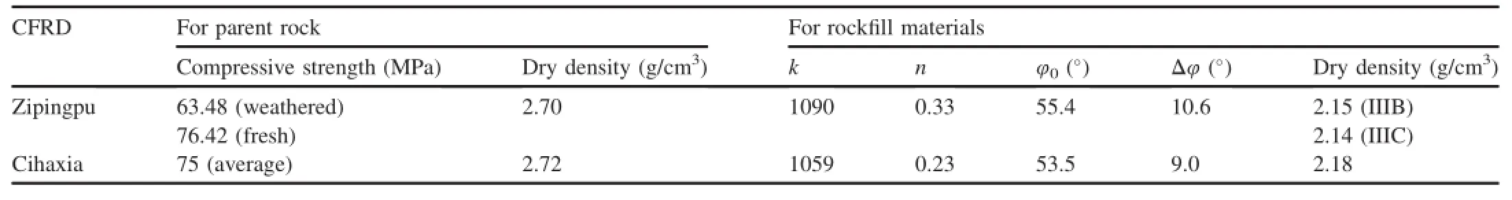
Table 2Physical and mechanical parameters of rockfill materials in Zipingpu and Cihaxia CFRDs.

Table 3Dynamic model parameters used in seismic response analysis.
5.Seismic responses of Zipingpu CFRD
5.1.Acceleration response
Fig.6 plots the contours of the amplif i cation coeff i cient of the base accelerations along the horizontal and vertical directions at the 0+251.00 m section.Two general trends can be observed along the horizontal direction.First,at the dam axis the amplif i cation coeff i cient is slightly less than 1.0 below an elevation of 850 m.However,it increases rapidly above this elevation to its maximum value(2.2)at the crest(Fig.6(a)). This is the well-known whipping effect in structural dynamics. Second,at the same elevation,the amplif i cation coeff i cient near the dam axis is lower than it is near the upstream and downstream slopes.This acceleration response is in good accordance with the experimental f i ndings of Wang and Zhang (2003)after centrifugal shaking table tests were conducted on a CFRD with a similar height(155 m).In their centrifuge model test,the input(peak)acceleration was 469.7 cm/s2, which is almost the same as that in Fig.5(b),and the amplifi cation coef fi cient at the crest was considered to be about 2.5. In the current case,the numerical simulation gives a maximum value of 2.2.After using the wavelet transform technique with the acceleration histories recorded by the seismographs installed at the crest,Kong and Zou(2014)suggested that the peak acceleration along the river was about 0.8g,where g is the gravitational acceleration,and therefore that the amplif ication coeff i cient was about 1.74,given a peak base acceleration of 0.46g.Our numerical results,shown in Fig.6(a),fall within the results given by Wang and Zhang(2003)and Kong and Zou(2014).
The distribution of the vertical amplif i cation coeff i cient follows a similar trend to the horizontal one,as shown in Fig.6(b).However,the maximum amplif i cation coeff i cient is about 2.4,slightly higher than the horizontal one.Kong and Zou(2014)used a peak acceleration of 1.2g along the vertical direction,which provided an approximate amplif i cation coeff i cient of 2.8,given a peak base acceleration of 0.43g. Since the Zipingpu dam is the first modern CFRD that has ever experienced such a strong earthquake,and unfortunately the base acceleration at the dam site was not recorded,it is still diff i cult to quantitatively evaluate the reliability of the numerical results given above.However,it is strong evidence that a modern CFRD designed and compacted according to the specif i cations will sustain an earthquake of such a magnitude without a slope failure.
5.2.Permanent deformation of dam

Fig.5.Base acceleration in different directions used in seismic responses analysis(provided by Professor Xiao-jun LI from China Earthquake Administration).
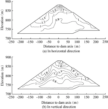
Fig.6.Amplif i cation coeff i cient of base accelerations in different directions in 0+251.00 m section.
One of the most remarkable phenomena caused by the Wenchuan earthquake was the evident settlement recorded by the deformation monitoring gauges at different elevations (Fig.2)and observed at the dam crest(Chen,2015;Kong and Zou,2014).Fig.7 is a plot of the contours of earthquakeinduced settlement in the 0+251.00 m section obtained through the finite element simulation.It is clear that the settlement increases as the elevation increases,and a maximum settlement of 92.4 cm accumulates at the crest.According to the measurements,the maximum settlement at an elevation of 850 m is about 81.0 cm in the 0+251.00 m section and 73.4 cm in the 0+371.00 m section.The observed settlement at the top of the parapet wall is about 74.4 cm after the earthquake.In addition,drill investigation at the crest shows that the pavement has separated from the settled rockfill materials during the earthquake and the gap in between is about 15—20 cm.Therefore,it can be inferred that the settlement at the crest may have a magnitude of 90—100 cm.This may be seen as evidence for the credibility of the numerical results.

Fig.7.Contours of earthquake-induced settlement in 0+251.00 m section(units:cm).

Fig.8.Comparison of calculated and observed earthquake-induced settlements in different sections.
Fig.8 compares the numerical and observed earthquakeinduced settlements at different elevations of the two monitoring sections.Once again,the numerical results agree with the observed data,both qualitatively and quantitatively.Using empirical formulas of permanent strains within the framework of the strain potential method seems to be an effective way of predicting the permanent deformation of CFRDs subjected to earthquakes.
5.3.Gap propagation under concrete slabs
Holes were drilled perpendicular to the concrete slabs to investigate the gap between the slabs and the cushion material, and it was found that a large area of third-stage concrete slabs (above an elevation of 845 m)had been separated from the settled cushion material(Song and Cai,2009).Fig.9 plots the gap propagation process under the concrete slabs through fi nite element analysis.Numerical results show that no obvious separation was observed before 32 s,and when the earthquake lasted 44 s,the first layer of slabs began to be separated from the rockfill layer.Afterward,the gap continued to propagate downward.Three layers of slabs were separated from the cushion at the instant of 68 s,and after the peak period of the main shock(80 s)the separated regions enlarged to include the top four layers of slabs,and the height of separated regions exceeded 30 m.
Fig.10 shows the contours of the gap width between the concrete slabs and the cushion layer.The gap width is in essence the normal differential displacement of the node pairs in the interface elements used for simulating the contact behavior between the concrete slabs and the cushion.The shaded area is the separated region revealed by drill investigation.It can be seen that the numerically predicted separated region coincides with the observed one,particularly under slabs 1—23.Under slabs 24—35,the numerical results slightly overestimate the separated region.However,the general trends are quite comparable to one another under all the concrete slabs.The finite element analysis gives a maximum gap width of 10.3 cm at the top of the concrete slabs near the 0+251.00 m section.Site investigations show that the maximum gap width under slabs 1—23 is about 7.0 cm and itis about 23.0 cm under slabs 36—39.These results indicate that the zero-thickness contact element(Goodman et al.,1968) that allows separation is effective for studying the gap propagation problem for CFRDs,at least in a qualitative manner.

Fig.9.Gap propagation process under concrete slabs during main shock in 0+251.00 m section.
5.4.Mechanism of failure of construction joints
The reservoir level was 828.65 m when the Wenchuan earthquake occurred,which was below the construction joints between the second-stage and third-stage concrete slabs.It was found during site inspection after the main shock that many of the construction joints at an elevation of 845 m experienced shear failure during the earthquake,as shown in Fig.11(a).For example,the relative displacement at the construction joints of slabs 5—12 was about 15—17 cm,and it was 12—15 cm at the construction joints of slabs 14—23 (Chen,2015;Kong and Zou,2014;Song and Cai,2009).After removal of the damaged concrete surface,it was further revealed that the steel rebar across the construction joints was also sheared to a zigzag shape,as shown in Fig.11(b).
Based on shaking table tests on a CFRD model,Kong et al. (2012a)inferred that the downward frictional force exerted upon the concrete slabs as a result of the settlement of the underlying rockfill materials and the outward normal force generated by the horizontal expansion of the rockfill materials were the main reasons for the failure of the construction joints in the Zipingpu CFRD.In addition,the seismic inertial force exerted upon the slabs was not the crucial factor causing the shear failure.

Fig.10.Comparison of calculated and measured separated regions under concrete slabs(units of gap width:cm).

Fig.11.Shear failure of construction joints at elevation of 845 m and zigzag rebar.
After analyzing the site observations,and with consideration of the numerical results,the authors believe that the frictional force was not the governing factor that initiated the shear failure of the construction joints.First,during the earthquake,the gap propagated downwards(Fig.9)and a frictional force could not generate along the separated interface.Second,the reservoir water level before the Wenchuan earthquake was below the construction joints between the second-stage and third-stage concrete slabs.Thus,the normal force on the contacting interface was quite small.It is well known that the shear force an interface can sustain is proportional to its normal force(Zhang and Zhang,2008). Therefore,it was impossible for a very large frictional force to accumulate along the contacting interface.Furthermore,the status of the interface between concrete slabs and rockfill materials rapidly shifted between contacting and being separated during the earthquake,and once the two neighboring materials were separated,the frictional force accumulated was bound to be released immediately.Field observations also show that the entire dam moved downstream during the earthquake,including the upstream rockfill materials.Therefore,the outward normal force is not responsible for the shear failure of construction joints at an elevation of 845 m.
In the authors'opinion,shear failure of the construction joints at an elevation of 845 m was an adverse consequence of the gap propagation under the concrete slabs.Numerical results show that the concrete slabs were separated from the cushion material gradually during the earthquake(Fig.9),and the interface in between had a special contacting status.That is,a certain region of the interface above the elevation of 845 m kept contact while the interfaces above this region were shaken open,as shown in Fig.12.Under such conditions,the concrete slabs served as cantilever plates,which had a tendency of rotation about the top of the contacting region under the combined action of gravity and seismic inertial forces (Fig.12).Such a rotation would result in a sharp decrease of the normal compressive stress or even a large magnitude of normal tensile stress at the horizontal joints,and therefore an evident decrease of the shear strength of the joints.It was also possible that tensile cracks appeared at the horizontal joints prior to the shear failure.That is to say,the rotation of the concrete slabs above an elevation of 845 m about the contacting region was the real reason for the failure of the horizontal construction joints.A strong piece of evidence that supported our conclusion was the presence of many tensile cracks above the failed joints(SIPZEMWR,2008),because a large magnitude of tensile stress was bound to occur near the fulcrum of the cantilever slabs,which were dragged by the gravity and seismic inertial forces.This particular observation could not be explained by the downward frictional forces suggested by Kong et al.(2012a).
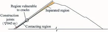
Fig.12.Mechanism of shear failure of horizontal construction joints.
6.Conclusions
TheZipingpuCFRDistheonlyhighdamofthistypethathas ever experienced a strong earthquake with a peak base acceleration of about 0.5g.This rare and valuable case provides us abundant data to investigate and validate the seismic responses of CFRDs,so as to guide the design and construction of high CFRDs in high-earthquake intensity regions.In this study,dynamic response analysis was conducted using the finite element method and an equivalent viscoelastic model for rockfill materials.Thepermanentdeformationofthedamwasalsostudiedby employing empirical formulas of accumulated strains established for rockfill materials.The following conclusions can be obtained based on the numerical results and field observations:
(1)An evident whipping effect was observed with numerical analysis,both along the river(horizontal)direction and along the vertical direction.The base excitation was not amplified within the lower half of the dam.However,the amplif i cation coeff i cients increased rapidly within the upper half of the dam and the horizontal and vertical amplif i cation coeff i cients reached 2.2 and 2.4 at the dam crest,respectively. Another f i nding was the larger acceleration response near the dam slopes than near the dam axis.These acceleration responses explain the loosening,rolling,and falling of the rockfill particles near the crest and along the downstream slope observed during field investigations after the Wenchuan earthquake.
(2)Earthquake shaking results in considerable settlement of the dam,which increases with the elevation signif i cantly.This is in accordance with the experimental f i nding that a rockfill sample generally undergoes a volume contraction during cyclic shearing.A detrimental consequence of the earthquakeinduced settlement is the separation of the pavement at the crest and the concrete slabs from the settled rockfill materials, as evidenced in the Zipingpu CFRD.In this case study,the permanent deformation of the dam and the relevant separated regions between concrete slabs and the cushion layer reproduced by finite element simulations agree with the field observations,which proves the effectiveness of the strain potential method and the corresponding model for permanent strains.
(3)Before the separation of concrete slabs from underlying rockfill materials,the slabs serve as plates on a rockfill foundation.However,gap propagation along the interface between concrete slabs and cushion material changes the working condition of the slabs into cantilever plates,which tend to rotate about the unseparated region under the combined action of gravity and seismic inertial forces.This effect results in a sharp decrease of the normal compressive stress or even considerable tensile stress along the horizontal plane of concrete slabs,and triggers the failure of the construction joints.
Since the damage to the concrete face slabs is a result of the settlement of the dam,it is clear that one of the most important aspects that should be taken into consideration in constructing a CFRD in high-seismic intensity regions may be the reduction of earthquake-induced permanent deformation.Increasing the density of rockfill materials by enhancing the compaction criteria,particularly for rockfill materials within the upper half of the dam,seems to be a rational choice.
In regard to the seismic response analysis method,the results obtained in this case study show that the equivalent linear method,incorporating a viscoelastic model for acceleration response as well as the strain potential method for permanent deformation analysis,is quite useful in studying the dynamic behavior of rockfill dams.However,it is important to note that an assumption implicated in such an analysis is the decomposition of the total strains of rockfill materials into a cyclic (viscoelastic)part and a permanent(plastic)part.Such a simplif i cation makes the prediction of stress within the concrete slabs unreliable,because the stress of concrete slabs is inf l uenced by the total displacement of the underlying rockfill materials.This is the reason that we cannot give a quantitative explanation for the failure of construction joints in this paper. In order to predict the stress history of concrete structures in CFRDs reliably,a constitutive model that can describe the hysteresis(energy dissipation)behavior and the permanent strain accumulation behavior in a unified manner is required. Unfortunately,such kinds of applicable models are not yet available,although signif i cant efforts have already been devoted to this area using different kinds of advanced constitutivemodeling frameworksin thepastdecades. Constitutive modeling of the dynamic behavior of rockfill materials is still a challenging task that needs further investigation.
Chen,S.S.,2015.Safety Problems of Earth and Rockfill Dams Subjected to Earthquakes.Science Press,Beijing(in Chinese).
Dakoulas,P.,2012.Nonlinear seismic response of tall concrete-face rockfill dams in narrow canyons.Soil Dyn.Earthq.Eng.34(1),11—24.http:// dx.doi.org/10.1016/j.soildyn.2011.09.004.
Feng,D.G.,Zhang,G.,Zhang,J.M.,2010.Three-dimensional seismic response analysis of a concrete-faced rockfill dam on overburden layers. Front.Archit.Civ.Eng.China 4(2),258—266.http://dx.doi.org/10.1007/ s11709-010-0031-4.
Fu,H.,Ling,H.,2009.Experimental Study on the Dam Materials Used in Cihaxia Concrete Face Rockfill Dam.Nanjing Hydraulic Research Institute,Nanjing(in Chinese).
Fu,Z.Z.,Chen,S.S.,Peng,C.,2014.Modeling cyclic behavior of rockfill materials ina framework of generalized plasticity.Int.J.Geomech 14(2), 191—204.http://dx.doi.org/10.1061/(ASCE)GM.1943-5622.0000302.
Fu,Z.Z.,Chen,S.S.,Wei,K.M.,2015.Dynamical Response Analysis Program for Earth and Rockfill Structures(DRAPERS),Theory and Manual. Nanjing Hydraulic Research Institute,Nanjing(in Chinese).
Goodman,R.E.,Taylor,R.L.,Brekke,T.L.,1968.A model for the mechanics of jointed rock.J.Soil Mech.Found.Div.94(3),637—660.
Gu,G.C.,Shen,C.S.,Cen,W.J.,2009.Earthquake Engineering for Earthrock Dams.China Waterpower Press,Beijing(in Chinese).
Idriss,I.M.,Sun,J.I.,1992.User's Manual for SHAKE91:A Computer Program for Conducting Equivalent Linear Seismic Response Analyses of Horizontally Layered Soil Deposits.University of California,Davis.
International Commission on Large Dams(ICOLD),2010.Concrete Face Rockfill Dams:Concepts for Design and Construction.China Waterpower Press,Beijing(in Chinese).
Kong,X.J.,Liu,F.H.,Liu,J.,2012a.Shaking table model tests on face-slab dislocation of concrete face rock-fill dams under earthquakes.Chin.J. Geotech.Eng.34(2),258—267(in Chinese).
Kong,X.J.,Zhou,Y.,Zou,D.G.,2012b.Study of seismic wave input of Zipingpu concrete face rockfill dam during Wenchuan earthquake.Rock Soil Mech.33(7),2110—2116(in Chinese).
Kong,X.J.,Zou,D.G.,2014.Zipingpu Concrete Face Rockfill Dam,Earthquake Damage Analysis and Numerical Simulations.Science Press,Beijing(in Chinese).
Shen,Z.J.,2000.Theoretical Soil Mechanics.China Waterpower Press,Beijing(in Chinese).
Site Inspection Panel of Zipingpu Engineering,Ministry of Water Resource (SIPZEMWR),2008.Safety Monitoring and Site Investigation Data of Zipingpu Concrete Face Rockfill Dam after“5.12”Wenchuan Earthquake. SIPZEMWR,Beijing(in Chinese).
Song,S.W.,Cai,D.W.,2009.Earthquake damage phenomena and deformation monitoring analysis for concrete faced rockfill dam at Zipingpu project during Wenchuan Earthquake.Chin.J.Rock Mech.Eng.28(4),840—849 (in Chinese).
Wang,N.X.,Zhang,W.M.,2003.Dynamical centrifuge model test for concrete face rockfill dam.Chin.J.Geotech.Eng.25(4),504—507(in Chinese).
Xiong,K.,Weng,Y.H.,He,Y.L.,2013.Seismic failure modes and seismic safety of Hardfill dam.Water Sci.Eng.6(1),199—214.http://dx.doi.org/ 10.3882/j.issn.1674-2370.2013.02.008.
Zhang,G.,Zhang,J.M.,2008.Unified modelling of monotonic and cyclic behavior of interface between structure and gravelly soil.Soils Found. 48(2),231—245.http://dx.doi.org/10.3208/sandf.48.231.
Zhong,H.,Wang,N.L.,Lin,G.,2013.Seismic response of concrete gravity dam reinforced with FRP sheets on dam surface.Water Sci.Eng.6(4), 409—422.http://dx.doi.org/10.3882/j.issn.1674-2370.2013.04.005.
Zhou,W.,Hua,J.J.,Chang,X.L.,2011.Settlement analysis of the Shuibuya concrete-face rockfill dam.Comput.Geotech.38(2),269—280.http:// dx.doi.org/10.1016/j.compgeo.2010.10.004.
Received 30 June 2015;accepted 18 September 2015
This work was supported by the National Natural Science Foundation of China(Grants No.91215301 and 51309161)and the Scientif i c Research Fund of the Nanjing Hydraulic Research Institute(Grants No.Y314011 and Y315005).
*Corresponding author.
E-mail address:fu_zhongzhi@yahoo.com(Zhong-zhi Fu).
Peer review under responsibility of Hohai University.
http://dx.doi.org/10.1016/j.wse.2016.09.002
1674-2370/©2016 Hohai University.Production and hosting by Elsevier B.V.This is an open access article under the CC BY-NC-ND license(http:// creativecommons.org/licenses/by-nc-nd/4.0/).
©2016 Hohai University.Production and hosting by Elsevier B.V.This is an open access article under the CC BY-NC-ND license(http:// creativecommons.org/licenses/by-nc-nd/4.0/).
猜你喜欢
杂志排行

Water Science and Engineering的其它文章
- Numerical analysis of rapid drawdown:Applications in real cases
- Stability analysis of unsaturated soil slope during rainfall inf i ltration using coupled liquid-gas-solid three-phase model
- Numerical simulation of seismic damage and cracking of concrete slabs of high concrete face rockfill dams
- Design considerations and behavior of reinforced concrete core dams during construction and impounding
- Numerical stress-deformation analysis of cut-off wall in clay-core rockfill dam on thick overburden
- Calibration and performance of two different constitutive models for rockfill materials