Implicit large eddy simulation of unsteady cloud cavitation around a planeconvex hydrofoil*
2015-12-01HIDALGOVictorLUOXianwu罗先武ESCALERXavierJIBin季斌AGUINAGAAlvaroBeijingKeyLaboratoryofCOUtilizationandReductionTechnologyTsinghuaUniversityBeijing0008ChinamailvictorhidalgoepneduecCDIFUniversitatPolitcnicadeCatalunyaBarcel
HIDALGO Victor, LUO Xian-wu (罗先武), ESCALER Xavier, JI Bin (季斌), AGUINAGA Alvaro. Beijing Key Laboratory of COUtilization and Reduction Technology, Tsinghua University, Beijing 0008,China, E-mail: victor.hidalgo@epn.edu.ec. CDIF, Universitat Politècnica de Catalunya, Barcelona, Spain. School of Power and Mechanical Engineering, Wuhan University, Wuhan 007, China. Mechanical Engineering Department, Escuela Politecnica Nacional University, Quito, Ecuador
Implicit large eddy simulation of unsteady cloud cavitation around a planeconvex hydrofoil*
HIDALGO Victor1, LUO Xian-wu (罗先武)1, ESCALER Xavier2, JI Bin (季斌)3, AGUINAGA Alvaro4
1. Beijing Key Laboratory of CO2Utilization and Reduction Technology, Tsinghua University, Beijing 100084,China, E-mail: victor.hidalgo@epn.edu.ec
2. CDIF, Universitat Politècnica de Catalunya, Barcelona, Spain
3. School of Power and Mechanical Engineering, Wuhan University, Wuhan 430072, China
4. Mechanical Engineering Department, Escuela Politecnica Nacional University, Quito, Ecuador
(Received March 10, 2015, Revised October 15, 2015)
The present paper focuses on the erosive cavitation behavior around a plane convex hydrofoil. The Zwart-Gerber-Belamri cavitation model is implemented in a library form to be used with the OpenFOAM. The implicit large eddy simulation (ILES) is applied to analyze the three dimensional unsteady cavitating flow around a plane convex hydrofoil. The numerical results in the cases under the hydrodynamic-conditions, which were experimentally tested at the high speed cavitation tunnel of the École Polytechnique Fédérale de Lausanne (EPFL), clearly show the sheet cavitation development, the shedding and the collapse of vapor clouds. It is noted that the cavitation evolutions including the maximum vapor length, the detachment and the oscillation frequency, are captured fairly well. Furthermore, the pressure pulses due to the cavitation development as well as the complex vortex structures are reasonably well predicted. Consequently, it may be concluded that the present numerical method can be used to investigate the unsteady cavitation around hydrofoils with a satisfactory accuracy.
implicit large eddy simulation (ILES), unsteady partial cavitation, Zwart-Gerber-Belamri cavitation model, OpenFOAM, Q -criterion
Introduction0F
Studies of unsteady cloud cavitations around hydrofoils are important to improve the design of the fluid machinery[1]and to understand the mechanisms around the cavitation dynamic behavior and the collapse of the cloud of bubbles. However, experiments are expensive and have limitations such as the accuracy of lab equipments. Therefore, the computational fluid mechanics (CFD) are a complementary option to understand the cavity shedding and collapse, the generated cyclic stresses and the resulting cavitation erosion.
In this way, Kunz et al.[2]proposed a cavitation model based on Merkle's ideas for the analysis of unsteady cavitating flow. The model considers the continuity of a mixture volume rather than a mixture mass equation. The transfer from liquid to vapor is modeled as being proportional to the liquid volume fraction and the pressure below the vapor pressure. For instance,Nouri et al.[3]studied unsteady cavitating flow over a disc using the OpenFOAM with the explicit LES based on this cavitation model. Their results show that the main aspects of the super cavitation could be captured. However, how to select a correct explicit subgrid model is shown to be a problem very much depending on different cases. Moreover, the shape of the cavity cluster can be improved with a cavitation model based on Rayleigh-Plesset's equation. Based on this premise, Roohi et al.[4]studied the cavitating flow over a Clark-Y hydrofoil and they compared the Kunz model with the Schnerr-Sauer cavitation model, which is based on the Rayleigh-Plesset's equation and is apart of the default OpenFOAM solver packages too. The corresponding results show that the Schnerr-Sauer model predicts a stronger re-entrant jet, which might be visible in experiment, and the shape of the obtained cavity is improved as well. However, it was found that the symmetrical consideration for condensation and vaporization processes may induce a great error of the force coefficients in the super cavitation regime.
Consequently, Zwart et al.[5]presented a two phase flow model for predicting cavitation dynamics which was implemented in CFX-5 based on the Rayleigh-Plesset's equation. The model works well for condensation, but is unstable for vaporization. Thus, an unsymmetrical consideration was taken into account with empirical constants for calibration. As a result, the model shows improvements for non-equilibrium effects, which were not included in previous models such as those of Schnerr-Sauer, Gerber[6]and Senocak and Shyy[7]. This model was used to capture the cavitation phenomenon with good results. That is the case of Ji et al.[8], who studied the horse-shoe cloud behavior over a twisted hydrofoil and predicted the performances of a marine propeller under the cavitation condition with different skew angles. Shi et al.[9]also made a remarkable use of the Zwart-Gerber-Belamri model for the study of cavitation in a WP7 automobile centrifugal pump. Zhang et al.[10]used this model to study the effects of the density ratio on the maximum length of the attached sheet cavity. Some studies were carried out to improve the model such as in the case of Morgut et al.[11], who determined the possible values of the calibration constants for numerical simulations. In this line, it was concluded that the evaporation coefficient controls the cavity length and the high vapor volume fraction, while the condensation vapor regulates the cavity length. Unfortunately, the cavitation model of Zwart-Gerber-Belamri is not a part of the OpenFOAM solvers and no references are available for its implementation. Therefore, its proper implementation and validation is desirable, which will be carried out in the current work.
Due to the high Reynolds numbers of cavitating flows in the hydro machinery, the traditional RANS and turbulence models must be adapted to predict the cavity sheet and the shedding process. Some examples are the cases of Huang and Wang[12]and Ji et al.[13],who used the partially-averaged Navier-Stokes (PANS)equations in the commercial code ANSYS-CFX for the cavitation simulation. The PANS is a hybrid turbulence model for the simulation from the RANS to the direct numerical simulation (DNS) based on the unresolved to total ratios of kinetic energy (fk)and dissipation (fε).Nevertheless, those ratios can only be obtained by a subgrid independence analysis and cannot be easily estimated according to Sharath and Girimaji. Another solution was proposed by Zuo et al.[14], who added a function to the k -ε turbulence model to consider the influence of variations of the density on the turbulence viscosity for the study of cavitation in a Francis turbine. For a better solution,Bensow and Bark[15]applied the OpenFOAM with the implicit large eddy simulation (ILES) instead of the RANS to simulate the formation of erosive cavitation. The ILES was selected to avoid the explicit coupling between the mass transfer modeling and the subgrid modeling. The ILES was validated by recent studies of aerospace and naval engineering for highly turbulent flows such as the flows over a fully three-dimensional swept-wing geometry and a marine propeller[16].
In summary, the main target of this paper is the implementation and validation of the Zwart-Gerber-Belamri cavitation model in the OpenFOAM using the ILES. Therefore, we intend to obtain accurate simulations of the shedding process of the partial cavitation,which is considered as the main mechanism of the material erosion. For validation purposes, the experimental results obtained by Escaler et al.[17]with a 2-D plane-convex hydrofoil at the École Polytechnique Fédérale de Lausanne (EPFL) high speed cavitation tunnel are used. Previous investigations with the OpenFOAM were focused on the NACA series or twisted geometries with unsteady cavitation[18,19]to compare the cavitation hydrodynamic behavior. In the present paper, the plane-convex hydrofoil is specifically investigated to reveal the unsteady cavitation dynamics.
1. Description of the numerical method
1.1 Implicit large eddy simulation
Continuity and Navier-Stokes equations are the basis of the LES, and they are as follows:

where u is the instant velocity,t is the time,i and j are the space coordinates.
In the ILES, Eqs.(1) and (2) are filtered for the use of approximation as


and some solutions are excluded[20].
Based on the following considerations:
(1) The product of filtered velocities is
(2) The subgrid stress tensor, which is the Reynolds stress tensor is
(3) The filtered strain tensor rate is
(4) The filtered viscous stress tensor is
Equation (4) is modified into the following form


1.2 Zwart-Gerber-Belamri cavitation model
In the cavitating flow, the medium is considered as a single fluid of two-phase homogeneous mixture with phase transformations between vapor and water. The vapor volume fractionα, the densityρ, and the dynamic viscosityµof the vapor-water mixture are as follows:
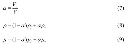
whereV is the total volume,landvare the subscripts for liquid and vapor, respectively. Thus, based on Eq.(3), to include the effect of the phase transformation, we have
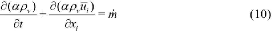
wherem˙is the inter-phase mass transfer rate per unit volume.
The Zwart-Gerber-Belamri model considers a variable bubble radius due to cavitation,R , which satisfies the following equation
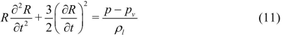
Based on Eq.(11), to neglect the second derivative term, we obtain a simplified expression as
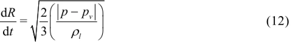
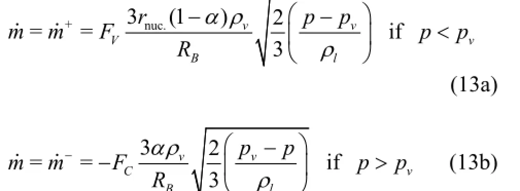
Thus the Zwart-Gerber-Belamri model is expressed by the following equations:
The Zwart-Gerber-Belamri model is implemented in the C++based OpenFOAM code. The code is saved on the new solver directory and compiled to become an implemented OpenFOAM's cavitation model for the present research.
1.3 OpenFOAM setup
The OpenFOAM version 2.2.x is used in the present research because it has eliminated the bugs of the previous version[18]. GNU/Linux Mint 6 Petra with kernel Linux 3.11.0-12-generic (x86 64) and XFCEdesktop are also applied. This version of the OpenFOAM is used especially in the CentOS GNU/ Linux distribution, which is based on the official GNU/Linux version of RedHAT. In fact, the following implementations are carried out:
(1) In the directory OpenFOAM/OpenFOAM-2.2.x/etc the text document bashrc is modified. The lines “foamCompiler=system” and “WMCOMPILER =Gcc” are added and the line “foamCompiler= Third-Party” is eliminated in the compiler location (#Compiler Location:). These are necessary to compile the implemented cavitation solver of Zwart-Gerber-Belamri[19].
(2) The library libmpi.so.1 is required in the GNU/Linux Mint Petra. Thus, a symbolic link (ln-s) with libmpi.so is implemented, which is a part of Message Passing Interface (MPI) GNU/Linux library.
2. Hydrofoil geometry, mesh generation and boundary conditions
2.1 Hydrofoil geometry and computation domain
Figure 1 shows a plane-convex hydrofoil used in Escaler's studies[17]. This hydrofoil has a plane upper surface and a convex lower surface, with a semicircular leading edge and a tip trailing edge. The chord lengthc of the hydrofoil is 0.0911 m, and the span is equal to0.3c.
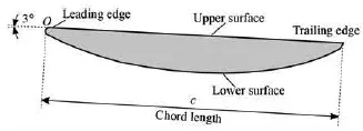
Fig.1 Plane-convex hydrofoil[17]
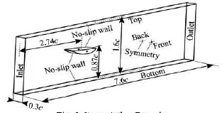
Fig.2 Computation domain
The hydrofoil is positioned in a computation domain with an angle of attackshown in Fig.2.
2.2 Mesh generation
Meshing is a challenge for this type of plane-convex hydrofoils due to the fact that the leading edge has an abrupt change from a convex shape to a plane shape with a semicircular leading edge.
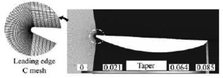
Fig.3 Structured and scale distributed mesh with taper analysis of the mesh around the plane-convex hydrofoil
Therefore, a structured C mesh is generated using Gmsh 2.8.5 and Salome 7.4.0 with a scale distribution and hexahedron elements. The resulting mesh has 393980 hexahedra. The quality of the mesh is guaranteed by the Salome taper analysis as indicated in Fig.3. This analysis shows proportional changes of elements such as 0.021, which is an acceptable value according to the previous studies[18].
The Yplus,y+, is calculated as
where uτis the friction velocity,yis the distance to the nearest hydrofoil wall andn is the kinematic viscosity[19].
The mean value for the hydrofoil wall is 9.2. This mean value is within the range from 1 to 15, which ensures that the mesh matches the conditions for the ILES based on Bensow et al.[15].
2.3 Boundary conditions
Under the cavitating conditions, the Reynolds number,Re , and the cavitation number,σ, are as follows:

where U∞is the free stream velocity,cis the chord length, and prand pvare the reference and saturation pressures, respectively.
Based on the experimental tests carried out by Escaler[17], five flow conditions combining the free stream velocity at the domain inlet, the angle of attack and the reference pressure at the domain outlet are selected as shown in Table 1. The uniform velocity andthe static pressure are assigned at the domain inlet and outlet.
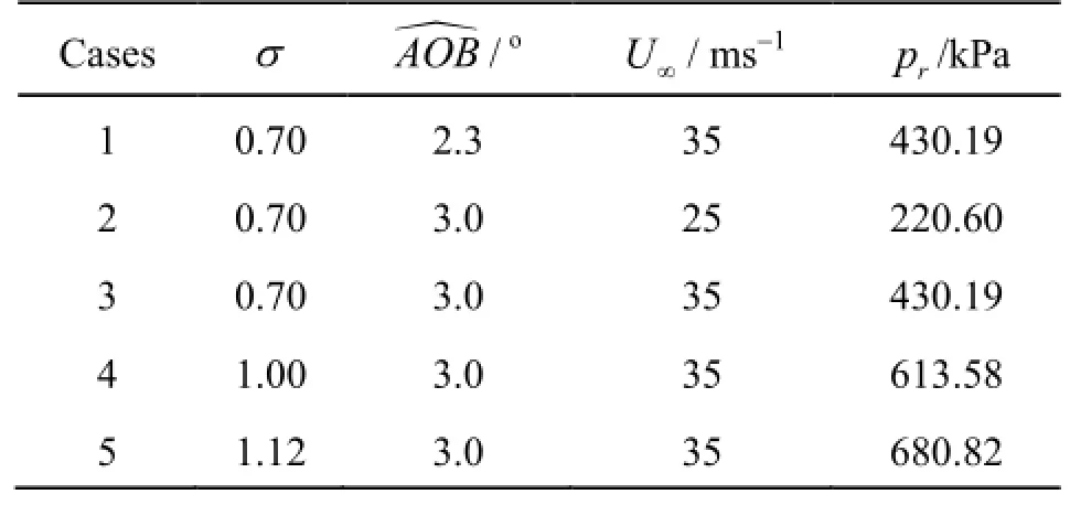
Table 1 Simulated flow conditions
The front and back planes of the domain are considered as the symmetry boundaries. Besides, the top and the bottom of the computation domain, and the hydrofoil surface are treated as no-slip walls.
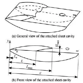
Fig.4 The characteristic parameters of a sheet cavity
3. Results and discussions
Figure 4 shows several characteristic parameters defined for the sheet cavity attached to the hydrofoil such as the cavity lengthL , the maximum cavity length Lmax, and the maximum cavity depth Hmax. The cavitating flow over the plane-convex hydrofoil sees a typical partial cavitation development consisting of an attached cavity from the leading edge. Under unsteady conditions, the re-entrant jet mechanism leads to the periodic shedding of bubble clouds[17].
Strouhal number,St , is a typical dimensionless parameter to show the feature of the cavity oscillation,as expressed as
where f is the cavity oscillation frequency.

Fig.5 Comparison of the leading edge cavity growth between the numerical simulation result and the experimental result for Case 1 in horizontal plane using iso-contour of
The transient numerical results are post-processed and analyzed along the time to identify a single period of the cavitation oscillation process. Particular attention is paid to the vapor volume fraction, the development of the reentrant jet, the shedding of a cloud cavity and its final collapse. The cloud cavity like the horse-shoe is visible and there is a good similarity between the experiment and simulation, as indicated in Fig.5.
For a better comparison, the dimensionless time is defined as
wheret is a time between the initial time,to, and the final time,tf, in one cycle. In particular, six time instants corresponding to 0, 1/6, 1/3, 1/2, 2/3 and 5/6 are selected, and the corresponding contours of the vapor volume fraction α=0.5are plotted in Fig.6, under all flow conditions.
Based on Fig.6, the following conclusions can be drawn:
(1) In all the cases, the growth and the detachment of the leading edge cavity, the break off and the collapse of the cavity cloud are shown.
(2) The maximum length of the leading edge attached cavity decreases with the increase of the cavitation number.
(3) When σ=0.7, the cavity cloud is observed more clearly in Cases 1 and 3 at U∞=35 m/sthan in Case 2 at U∞=25 m/s. Therefore, the larger velocity enhances the probabilities of the cloud cavity, which has a direct link with the erosive power of the cavitation.

Fig.6 Cavitation evolution in Cases 1 through 5 in 3-D using contour-surfaces of the vapor volume fraction (α=0.5)
(4) Cavities at the hydrofoil trailing edge are observed along the lower surface of the hydrofoil in three cases with σ=0.7. This kind of cavitation is due to the hydrofoil convex shape, and it is also observed in the experiments.
(5) It is noted that the present results obtained by the ILES method have as good accuracy as those of our previous studies[21]based on the explicit subgrid model of the LES.
In order to understand the effects of the cavitation evolution shown in Fig.6, the pressure coefficient, Cp, is expressed as

where psis the static pressure, and the vapor void fraction,α, are plotted in Fig.7 and Fig.8, respectively. Note that the two figures show the results at six points located along the upper surface at0.15c in the spanwise direction.
According to the definition ofσand Cp, the following relation holds true:

Due to the fact that psis always larger than or equal to pv,Cpmust be larger than or equal to -σ.
Because in those cases with σ=0.7, a large cavity length is involved, the flat Cplines, whose value corresponding to a negative value of the cavitation number can be observed at x/ c=0.2 and 0.4, compared with other cases. On the contrary, the cavity length in Case 5 is the shortest, and the static pressure oscillates violently even at x/ c =0.2. For x/ c=0.6 through 1.0,Cplines with strong pressure oscillations are observed in all cases. At the downstream of the hydrofoil (x/ c=1.2), the average static pressure is basically around the reference pressure level, and some pressure pulses are captured. Those pulses may be related with the collapse of small vapor clusters. Based on the vapor volume fraction oscillations shown in Fig.8, the vapor sizes are large in Cases 1 and 3, and is the smallest in Case 5 due to its highest reference pressure.
The comparison of the cavity length among those five cases is listed at Table 2, where both experimental and simulation data are included. To show the difference between the experiment and the calculation,we may define the relative error evaluation of the maximum cavity length as
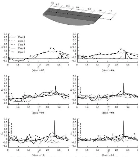
Fig.7 Local pressure coefficient,Cp, versus dimensionless time,ξ, in Cases 1 through 5 for different values of x/ c
The prediction accuracy is fairly good, though the largest error is near 20%. It must be noted that due to the transient nature of the shedding process and the high frequencies of the cavitation evolution during the tests[17], the maximum cavity length could not be determined with a sufficient accuracy from the experiments, and an error of about 5% might be reasonable. For a better understanding of the cavitation phenomenon, we define
whereΩis the vorticity rate, andSis the strain rate. The Q-criterion may be used to obtain the 3-D vorticity distribution.
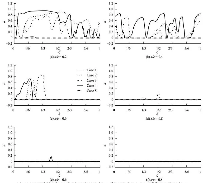
Fig.8 Vapor void fraction,α, versus dimensionless time,ξ, in Cases 1 through 5 at different values of x/ c

Table 2 Numerical and experimental results based on Lmax
The Q-criterion is plotted in Fig.9, where the contours of Q=2× 10⁵s-2show similarities with the vapor volume fraction contours (α=0.5). Results show that there is a strong interaction between the vorticity and the cavitation evolution.
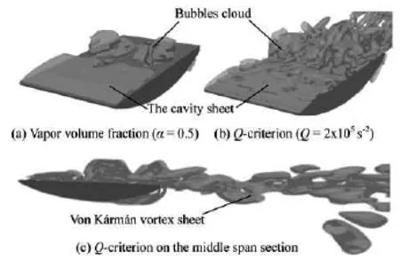
Fig.9 Vapor and vortex interaction
4. Conclusion
A numerical simulation of the unsteady cloud cavitation around a plane convex hydrofoil is carried out with a free OpenFOAM software package based on the ILES and a newly implemented Zwart-Gerber-Belamri cavitation model. The transient results under different operation conditions show the typical cavitation dynamic behaviors, including the growth of the leading edge cavity, the development of the reentrant jet, the shedding of the cavity cloud and its collapse. The comparison between the numerical and experimental results indicates that the cavitation evolution is simulated fairly well. Further, the pressure oscillation due to the cavitation dynamics as well as the complex vortex structures shown by the Q-criterion are reasonably well predicted. Therefore, the proposed numerical method and the implemented Zwart-Gerber-Belamri cavitation model in OpenFOAM are validated as reliable tools to investigate the unsteady cavitation around hydrofoils.
Acknowledgements
This work was supported by the Beijing Key Laboratory Development Project (Grant No. Z151100001615006), the State Key Laboratory of Hydroscience and Engineering, Tsinghua University(Grant Nos. 2014-KY-05, 2015-E-03).
[1] LUO Xian-wu, JI Bin and XU Hong-yuan. Design and optimization for fluid machinery[M]. Beijing, China:Tsinghua University Press, 2012, 24-26(in Chinese).
[2] KUNZ R., BOGER D. and STINEBRING D. et al. A preconditioned Navier Stokes method for two-phase flows with application to cavitation prediction[J]. Computers and Fluids, 2000, 29(8): 849-875.
[3] NOURI N., MOGHIMI M. and MIRSAEEDI S. Numerical simulation of unsteady cavitating flow over a disc[J]. Proceedings of the Institution of Mechanical Engineers, Part C: Journal of Mechanical Engineering Science, 2010, 224(6): 1245-1253.
[4] ROOHI E., ZAHIRI A. and ANDIDEH-FARD M. Numerical simulation of cavitation around a two-dimensional hydrofoil using VOF method and LES turbulence model[J]. Applied Mathematical Modelling, 2013,37(9): 6469-6488.
[5] ZWART P., GERBER A. and BELAMRI T. A twophase flow model for predicting cavitation dynamics[C]. Proceedings of International Conference on Multiphase Flow ICMF 2004. Yokohama, Japan, 2004.
[6] GERBER A. A CFD model for devices operating under extensive cavitation conditions[C]. Proceedings of IMECE. New Orleans, Louisina, 2002.
[7] SENOCAK I., SHYY W. Evaluation of cavitation models for Navier-Stokes computations[C]. Proceedings of FEDSM. Montreal, Quebec, Canada, 2002.
[8] JI B., LUO X. and WU Y. Unsteady cavitation characteristics and alleviation of pressure fluctuations around marine propellers with different skew angles[J]. Journal of Mechanical Science and Technology, 2014,28(4): 1339-1348.
[9] SHI W., WANG C. and WANG W. et al. Numerical calculation on cavitation pressure pulsation in centrifugal pump[J]. Advances in Mechanical Engineering,2014, 6(1): 3676311-3676318.
[10] ZHANG G., SHI W. and ZHOU L. et al. Effect of the maximum density ratio between liquid and vapor on cavitating simulation[J]. American Journal of Engineering and Applied Sciences, 2015, 9(1): 119-126.
[11] MORGUT M., NOBILE E. Influence of the mass transfer model on the numerical prediction of the cavitating flow around a marine propeller[C]. Proceeding of the Second International Symposium on Marine Propulsors. Hamburg, Germany, 2011.
[12] HUANG Biao, WANG Guo-yu. Partially averaged Navier-Stokes method for time-dependent turbulent cavitating flows[J]. Journal of Hydrodynamics, 2011,23(1): 26-33.
[13] JI B., LUO X. and WU Y. et al. Partially-averaged Navier Stokes method with modifiedk model for cavitating flow around a marine propeller in a non-uniform wake[J]. International Journal of Heat and Mass Transfer, 2012, 55(2324): 6582-6588.
[14] ZUO Z., LIU S. and LIU D. et al. Numerical predictions of the incipient and developed interblade vortex lines of a model Francis turbine by cavitation calculations[J]. Advances in Mechanical Engineering, 2013, 5(1):3975831-3975837.
[15] BENSOW R., BARK G. Simulating cavitating flows with LES in OpenFoam[C]. Proceeding of V European Conference on Computational Fluid Dynamics. Lisbon, Portugal, 2010.
[16] BENSOW R., LIEFVENDAHL M. Implicit and explicit subgrid modeling in LES applied to a marine propeller[C]. Proceeding of 38th Fluid Dynamics Conference and Exhibit. Seattle, Washington, 2008.
[17] ESCALER X., FARHAT M. and EGUSQUIZA E. et al. Dynamics and intensity of erosive partial cavitation[J]. Journal of Fluids Engineering, 2007, 129(7): 886-893.
[18] HIDALGO V., LUO Xian-wu and JI Bin et al. Numerical study of unsteady cavitation on 2D NACA0015 hydrofoil using free/open source software[J]. Chinese Science Bulletin, 2014, 59(26): 3276-3282.
[19] HIDALGO V., LUO X. and ESCALER X. et al. Numerical investigation of unsteady cavitation around a NACA 66 hydrofoil using OpenFOAM[J]. IOP Conference Series: Earth and Environmental Science,2014, 22(5): 0520131-0520138.
[20] ADAMS N., HICKEL S. and FRANZ S. Implicit subgrid-scale modeling by adaptive deconvolution[J]. Journal of Computational Physics, 2004, 200(2): 412-431.
[21] JI Bin, LUO Xian-wu and PENG Xiao-xing et al. Three-dimensional large eddy simulation and vorticity analysis of unsteady cavitating flow around a twisted hydrofoil[J]. Journal of Hydrodynamics, 2013, 25(4):510-519.
* Project supported by the National Natural Science Foundation of China (Grant Nos. 51306018, 51536008 and 51179091).
Biography: HIDALGO Victor (1985-), Male, Ph. D. Candidate(Tsinghua University), Associate Professor (EPN)
LUO Xian-wu,
E-mail:luoxw@mail.tsinghua.edu.cn
杂志排行

水动力学研究与进展 B辑的其它文章
- An effective method to predict oil recovery in high water cut stage*
- Experimental study of breach process of landslide dams by overtopping and its initiation mechanisms*
- Prediction of ship-ship interactions in ports by a non-hydrostatic model*
- Flow hydrodynamics in embankment breach*
- The variations of suspended sediment concentration in Yangtze River Estuary*
- Experimental investigation of motion responses of tunnel element immerging by moored barge*