High-precision method of detecting motion straightness based on plane mirror interference
2015-04-22DENGYongjun邓勇军ZHANGZhijing张之敬JINXin金鑫XUZhiyao许志尧SUNHongchang孙宏昌
DENG Yong-jun(邓勇军), ZHANG Zhi-jing(张之敬), JIN Xin(金鑫),XU Zhi-yao(许志尧), SUN Hong-chang(孙宏昌)
(School of Mechanical Engineering, Beijing Institute of Technology, Beijing 100081,China)
High-precision method of detecting motion straightness based on plane mirror interference
DENG Yong-jun(邓勇军), ZHANG Zhi-jing(张之敬), JIN Xin(金鑫),XU Zhi-yao(许志尧), SUN Hong-chang(孙宏昌)
(School of Mechanical Engineering, Beijing Institute of Technology, Beijing 100081,China)
A high-precision method of detecting motion straightness was proposed based on the principle of plane mirror interference after analyzing the motion straightness error of a linear stage. Detection experiments were carried out and the motion straightness errors were separated by the linear regression method. Finally, linear measurement uncertainty of the detection method was estimated. The results showed that this detection method was simple and accurate, and was especially suitable for precision detection of motion straightness error in the small travel movement of ultra-precision machining.
motion straightness; plane mirror interference; uncertainty; high-precision
Currently, laser interferometer straightness accessories (including Wollaston prism and dual plane mirror, etc.) are mainly adopted to detect the motion straightness error of machine tool guideways, and the measurement range can be up to 30 m. However, the straightness accessories are expensive and the measurement accuracy is low, typically about ±0.7 μm/m, so it can’t meet the high-precision measurement requirement, especially for sub-micron ultra-precision machine tools. Therefore, a high-precision method of detecting motion straightness based on plane mirror interference is proposed. Its linear measurement uncertainty can achieve 0.2 μm under normal conditions in small travel movement (0-50 mm). This method has broad applicability for precision miniature machining, in which requirement of measurement accuracy is always on submicron level.
1 Motion straightness error analysis
For moving parts of a machine tool, when the slide and guideway are assembled, the slide movement is not as ideal as translation along a given direction but in all directions with a slight translation and rotation, which is often referred to as motion error. The displacement deviation of slide motion trajectory from the ideal straight line is known as motion straightness error. The slide ups and downs in motion is controlled by the straightness in the vertical plane, which not only ensure the movement direction accuracy, but also ensure the slide have a good contact with the guideway. The straightness in the horizontal plane will directly affect the geometric accuracy of the machined parts, especially for cylindrical parts machined by lathes and other machine tools. The influence extent is far beyond the straightness in vertical plane. Therefore, the motion straightness in horizontal plane is taken as an example afterwards.
Assuming that the ideal motion axisxand the actual motion axisx′ of slide are both in the horizontal plane. There is an angle deviationαbetween the axisxandx′ as shown in Fig.1, which is caused by manufacturing errors and assembly errors etc., and it is the main component of slide motion error[1-2]. The linear motion error of the slide to any pointIin the horizontal plane is denoted bye(xi), which is the position deviation of the slide when the ideal motion axis as a reference.
e(xi) is composed of motion straightness errorδy(xi) and axial alignment errorr(xi).δy(xi) is displacement deviation in theY-axis direction due to the slide movement along the actual motion axis.r(xi) is caused byα,iis the sampling point along thex-axis,i=1,…,n.
The slide starting position is coordinate originOand end abscissa denoted byL. At any pointI, slide motion errore(xi) can be expressed as
e(xi)=δy(xi)+r(xi)
(1)
r(xi)=xiα
(2)
δy(xi)=e(xi)-xiα
(3)
To simplify the calculation, the errors of initial point are considered as 0, from the above equations, bothe(xi) andr(xi) need to be obtained in order to calculate the motion straightness error.
2 Detection principle
Laser interferometer is highly accurate for length measurement. Take Renishaw XL-80 as an example. Assuming measurement distance is 100 mm, the length measurement precision can reach ±0.05 μm, and the resolution can be 1nm when configuring the environment compensation unit in 0-40 ℃ environment. However, straightness measurement accuracy is only ±0.65 μm and the resolution is 10 nm by using straightness accessories. So it is difficult to meet the requirements for ultra-precision machining of submicron accuracy when using the straightness accessories of laser interferometer. The plane mirror interference method[3-5]takes advantages of length measurement with laser interferometer, and can measure errors perpendicular to the slide motion direction. The measuring principle is shown in Fig.2.
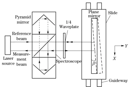
Fig.2 Detection schematics
The laser emitted by laser source is split into two beams by a spectroscope, one returns from a pyramid mirror as a reference beam, the other transmits as a measuring beam, and interferes with reference beam after through the quarter wave plate four times. The optical path length of measuring beam is twice of common length measuring by the laser interferometer , so the measurement resolution is also doubled.
Theoretically,e(xi) will be got by the method of plane mirror interference directly, andδy(xi) at any point can be obtained according to Eq.(1) by remove the linear component (i.e. axial alignment error) from the error curve with the least square method. However, due to the existence of a tiny deflectionβ(as shown in Fig.2) between plane mirror fixed position and ideal motion axis of slide inevitably, an additional displacements(xi) is produced.
s(xi)=xiβ
(4)
Actual measured values of the interferometer can be expressed as
eout(xi)=δ′y(xi)+r(xi)+s(xi)
(5)
The actual straightnessδ′y(xi) can be obtained by using the least square method[6-7]to remove the linear component according to
δ′y(xi)=eout(xi)-xi(α+β)
(6)
3 Experiments and data processing
3.1 Detection experiments
Experiments were carried out on a linear stage, which has linear slide structure that can travel 200 mm and has nominal straightness of ≤5 μm/100 mm. The environment temperature is 20±1 ℃, and automatic compensation unit was used for compensating temperature, humidity and thermal expansion. The plane mirror used in experiments is 80 mm length ×60 mm width with flatness ofλ/10(λ=633 nm). As the position of laser source was fixed and plane mirror accompanied with slide movement, the slide movement range must be less than the length of plane mirror. Set slide movement rangeLto be 50 mm, single-step to be 0.5 mm, and single-step interval to be 2 s to facilitate automatic data collection by laser interferometer. Take the measurements a total of five times, and collect 101 points each time. The actual measuring devices are shown in Fig.3.
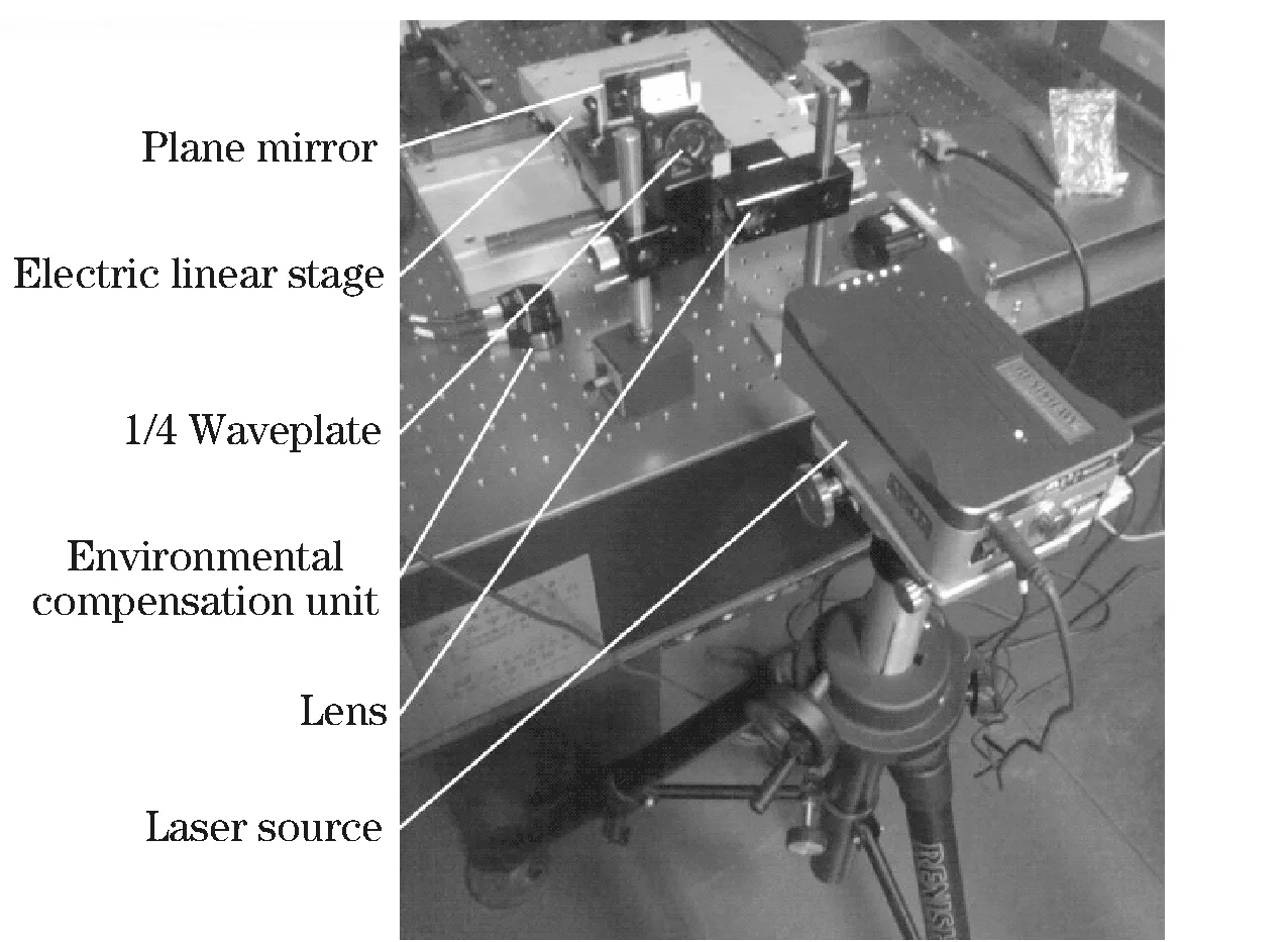
Fig.3 Experimental setup
The motion straightness errorsδ′y(xi) obtained after removing the linear components from experimental values by using least square method, as shown in Fig.4, and the abscissas represent the measured points.
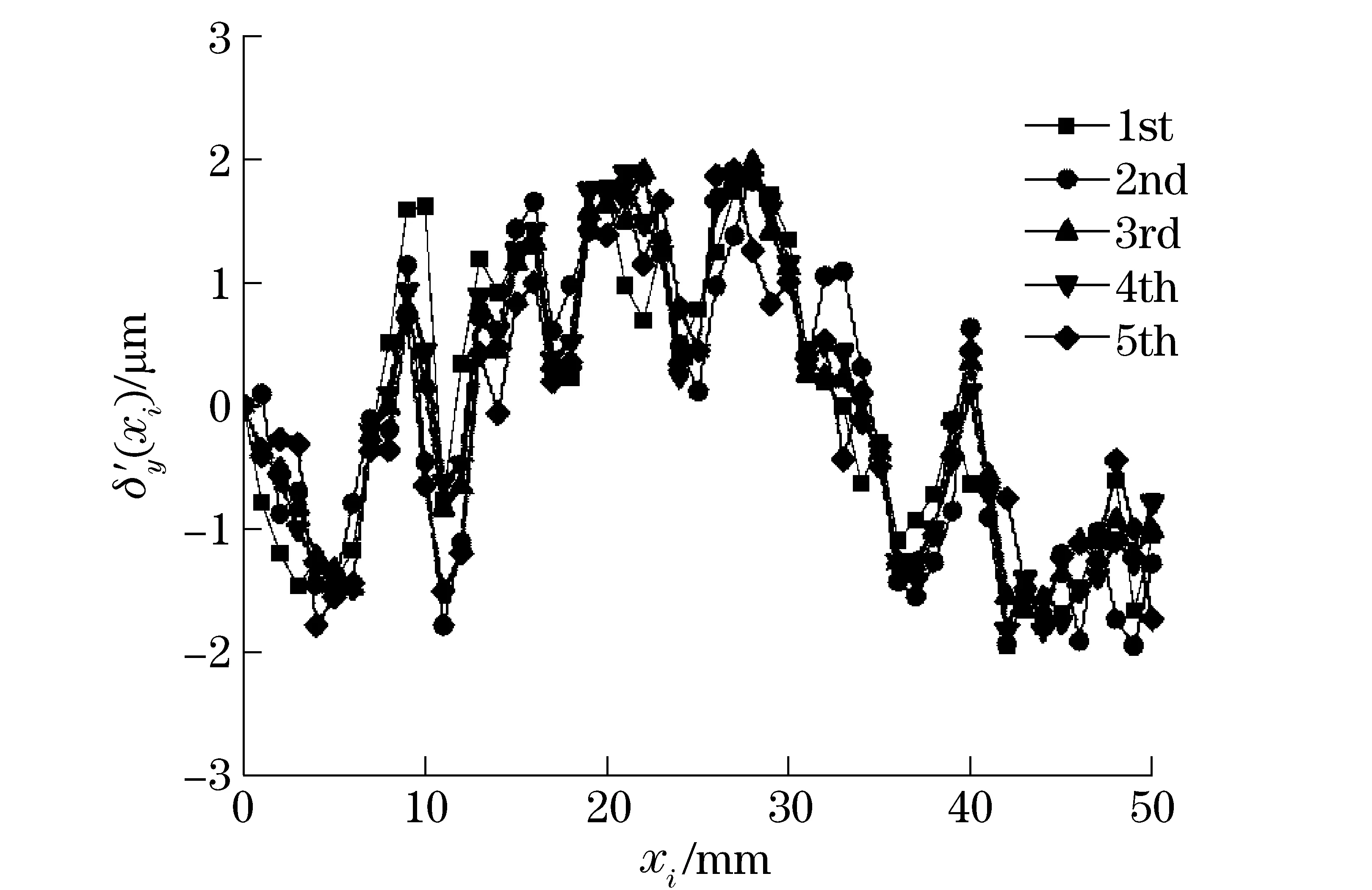
Fig.4 Experimental results
From the above experimental results, motion straightness error of the linear stage is less than ±2 μm in the travel range of 50 mm, and the results have a good repeatability in more times.
3.2 Uncertainty estimation
There were many primary factors affecting the measurement accuracy, such as the system error of laser interferometer, the flatness error of plane mirror, the dead zone error, cosine error, abbe error, and the material dead zone error, etc. Uncertainties caused by these factors were analyzed and the general linear measurement uncertainty was estimated[8-9].
① UncertaintyU1caused by the system error of laser interferometer
After automatic compensation for temperature and humidity, the system accuracy in linear measurement with Renishaw XL-80 can be up to ±0.5×10⁻⁶. It’s mainly related to the dead zoneL1and the measuring distanceL, as shown in Fig.5. In the measurement process,L1was about 100 mm andLwas 50 mm, so the uncertaintyU1caused by the system error of laser interferometer is
U1=(L+L1)×(±0.5×10⁻⁶)=(0.05+0.1)×(±0.5×10⁻⁶)m=±75 nm
(7)
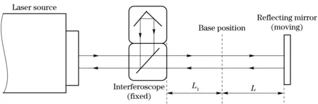
Fig.5 Dead zone error principle
② UncertaintyU2caused by the flatness error of plane mirror
The flatness error of plane mirror used in the measurement isλ/10(λ=633 nm), so uncertaintyU2caused by the flatness error of plane mirror is about 63.3 nm.
③ UncertaintyU3caused by the dead zone error
As shown in Fig.5, when the measurement conditions (including ambient temperature, atmospheric pressure and relative humidity) changed, the laser wavelength was also changed on the entire optical path (L1+L) at the same time. But onlyLwas compensated by environmental compensation unit in fact, so dead zone error was generated as it wasn’t compensated on optical pathL1.
When the dead zone exists, the measurement errors caused by the change of ambient temperature ΔT, the change of atmospheric pressure ΔPand the change of relative humidity ΔH, respectively are ±L1×10-6×ΔT/1, ±L1×10-6×ΔP/3.3 and ±L1×10-6×ΔH/50%.
In the experiments, the changes of the measurement conditions were ΔT=0.3 ℃, ΔH=6%, ΔP=0.3 MPa. The uncertaintyU3caused by the dead zone error is
(8)
④ UncertaintyU4caused by cosine error and abbe error
In the measurement, the plane mirror was fixed on the linear stage’s center and parallel to its motion direction. The laser was perpendicular to linear stage’s motion direction. So the uncertaintyU4caused by the cosine error and abbe error were negligible.
⑤ UncertaintyU5caused by the material dead zone error
In the linear positioning accuracy measurement, material expansion compensation is executed on the material length equal to the measuring distance. In this measurement, lens were fixed on the vibration isolation platform, and they were stationary, so the uncertaintyU5caused by the material dead zone of the measured object can be estimated through the change of the laser interferometer reading, which was about 50 nm.
⑥ UncertaintyU6caused by linear regression
The standard deviationSof the linear regression is expressed as
(9)
wherenis sampling number,Sis also called residual standard deviation, and it can estimate the impact of all the random factors ony. The smallerSis, the higher the accuracy of the linear regression is.Scan be seen as the linear regression uncertainty when the independent variablexis determined, namely
U6=S=13.89 nm
(10)
⑦ General linear measurement uncertaintyU
According to the root-sum-square principle, the linear measurement uncertaintyUcan be expressed as
(11)
Therefore, the linear measurement uncertainty of the motion straightness detection method based on plane mirror interference is about 115 nm and can meet the requirement of the submicron level precision measurement, which is much higher than the method by using straightness accessories of ±0.65 μm.
4 Conclusion
A high-precision detection method of motion straightness error based on a plane mirror interference was proposed in this paper. The detection method is simple, and especially suitable for precision detection of motion straightness error in the small travel movement of ultra-precision machining. The accuracy of this detection can be up to 100 nm if using a plane mirror with higher flatness accuracy. In addition, this method lays a foundation for the motion straightness error compensation.
[1] Gao W, Lee J C, Arai Y, et al. Measurement of slide error of an ultra-precision diamond turning machine by using a rotating cylinder workpiece[J]. International Journal of Machine Tools & Manufacture, 2010, 50(4):404-410.
[2] Ekinci T O, Mayer J R R. Relationships between straightness and angular kinematic errors in machines[J]. International Journal of Machine Tools and Manufacture, 2007, 47(12-13):1997-2004.
[3] Zhu Lingjian, Li Lin, Liu Junhua. A method for measuring the guideway straightness error based on polarized interference principle[J]. International Journal of Machine Tools & Manufacture, 2009, 49(3-4):285-290.
[4] Sun Changku, He Mingxia, Wang Peng. Laser measurement technology[M]. Tianjin:Tianjin University Press, 2008. (in Chinese)
[5] Zhu Jia, Li Xingfei, Tan Wenbin, et al. Method of geometric error detection for measuring machine based on laser interferometer[J]. Journal of Mechanical Engineering, 2010, 46(10): 25-30.
[6] Wu Shilin, Zhang Qi. Error analysis and data processing[M]. Beijing: Tsinghua University Press, 2010. (in Chinese)
[7] Dhanish P B, Mathew J. A fast and simple algorithm for evaluation of minimum zone straightness error from coordinate data[J]. The International Journal of Advanced Manufacturing Technology, 2007, 32(1-2): 92-98.
[8] Fang Xinxin, Wang Zigang. Uncertainty in measurement of positional deviation of coordinate measuring machine’s X-Direction[J]. Chinese Journal of Scientific Instrument, 2002, s3:171-173.(in Chinese)
[9] Liu Qing, Shao Zhixin. Discussion of linear fitting uncertainty of regress analysis[J].China Measurement & Test, 2009, 5(3): 41-44. (in Chinese)
(Edited by Cai Jianying)
10.15918/j.jbit1004-0579.201524.0406
TH 701 Document code: A Article ID: 1004- 0579(2015)04- 0466- 05
Received 2014- 02- 12
Supported by National Defense Basic Scientific Research Project(A222013); High Quality CNC Machine Tool and Basic Manufacturing Equipment Scientific Major Project (2012ZX04010-061)
E-mail: zhzhj@bit.edu.cn
猜你喜欢
——专访淮南寿阳眼镜总经理金鑫
杂志排行

Journal of Beijing Institute of Technology的其它文章
- Influence of shear sensitivities of steel projectiles on their ballistic performances
- Triaxial high-g accelerometer of microelectro mechanical systems
- Dynamic modeling and simulation for the rigid flexible coupling system with a non-tip mass
- Multi-constrained model predictive control for autonomous ground vehicle trajectory tracking
- Estimating the clutch transmitting torque during HEV mode-switch based on the Kalman filter
- Optimal tracking control for automatic transmission shift process