Measurement and analysis of Doppler shift for high-speed rail scenario①
2015-04-17DingJianwen丁建文
Ding Jianwen (丁建文)
(State Key Laboratory of Rail Traffic Control and Safety, Beijing Jiaotong University, Beijing 100044, P.R.China)
Measurement and analysis of Doppler shift for high-speed rail scenario①
Ding Jianwen (丁建文)②
(State Key Laboratory of Rail Traffic Control and Safety, Beijing Jiaotong University, Beijing 100044, P.R.China)
Based on the analysis of the impact of Doppler shift to the railway dedicated mobile communication quality under the condition of high-speed mobility, this paper presents a Doppler shift measurement approach based on the phase estimation of frequency correction channel (FCCH) which correctly reflects the time-varying characteristic of the channel with a testing system developed. The Doppler shift data under the high-speed condition is collected, processed, analyzed, and compared with the simulation results. The scientific laws of the Doppler shift distribution of radio channel under high-speed condition are obtained. These data and analysis are essential for the establishment of high-speed railway Doppler power spectrum model and the development of the key technology of anti-Doppler shift.
Doppler shift, high-speed railway (HSR), phase estimation, software radio
0 Introduction
A high-speed railway (HSR) propagation channel which belongs to wireless multipath fading channel has a significant impact on the design and performance analysis of wireless train control systems[1,2]. One of the main features of the HSR channel is time-varying characteristic[3]. It is required that it should be able to track the time-varying rate and remove or diminish the fading and Doppler shift of the received signal caused by the time-varying of the channel[4].
Compared with low-speed motion, the most obvious problem of the wireless channel under the HSR condition is the much higher Doppler shift, which will lead to signal distortion, and thus, result in the deterioration of communication quality. Doppler shift can also lead to obvious time-varying of the wireless multipath fading channel, deteriorating the performance of algorithms like channel estimation and equalization, etc.[5]. Therefore, the time-varying characteristic of the wireless multipath fading channel can be obtained by studying Doppler shift of the channel, and then its impact on the communication quality under the HSR condition can be analyzed. Correspondingly, the Doppler shift correction technology can be studied.
In Ref.[6], the tuned free-space path loss models in high speed railway considering Doppler effect and simulation results are proposed. Previous channel Doppler shift measurement campaigns investigate mainly the car-to-car (C2C) and car-to-infrastructure (C2I) cases[7-11]. In Refs[7,8], the radio channel is investigated at the frequency band of 2.4GHz. In Ref.[9], it presents a narrowband measurement campaign at 5.2GHz. Measured and simulated Doppler spectra for a frequency selective C2I channel are reported in Ref.[10]. For the C2C and C2I cases, Ref.[11] carries out a C2X radio channel measurement campaign in the 5GHz band to investigate and analyze the joint spatio-temporal Doppler spectra.
For the application of LTE in HSR, Ref.[12] adopts the Winner II model, the Doppler shift HSR channel model and the large-scale model based on field measurements to analyze the performance of LTE-R. In Ref.[13], the approximating function is used to estimate the Doppler frequency when the distance from the high-speed terminal to the base station is relatively close. In Ref.[14], the authors propose an algorithm of joint channel estimation and Doppler frequency offset estimation based on Ricean channel model. However, these works only conduct theoretical calculating and simulation for Doppler shift.
To the best of the authors’ knowledge, there is no publicly reported measurement data related to Doppler shift under the HSR condition. This paper presents a Doppler shift measurement method and based on that, measurement campaigns are performed at the frequency of 930 MHz of the GSM-R system in high-speed railway. Then, simulation and quantitative analyzing of dynamic characteristics of Doppler shift are conducted. Thus, the HSR Doppler shift model could be built.
1 Measurement campaign
1.1 Measurement method
Doppler shift measurement method presented by this paper realizes the measuring by using phase estimation of the FCCH.
Since the propagation delay from the transmitter to the receiver is generally unknown, carrier synchronization must be derived at the receiver. Taking GSM-R system as an example, The base station (BS) should send signals on the broadcast control channel (BCCH) to enable the mobile station (MS) to synchronize itself to BS[15]. The precondition of the synchronization is the capture of frequency correction bursts in FCCH which prepares MS for finding and demodulating the synchronous chanel (SCH) of the cell. The frequency shift of the signal can be estimated by capturing FCCH which corresponds to a pulse sequence of the frequency correction burst (FB). In each 51 multiframe of the GSM-R control channel, the FCCH burst is mapped into No. 0, 10, 20, 30 and 40 of multiframe, which transmit frequency information to MS. All the 148 bits of FB are 0 in binary, whose structure is shown in Fig.1[16]. FCCH after GMSK modulation is a pure sine wave, whose frequency is 67.5kHz higher than center frequency of the carrier.
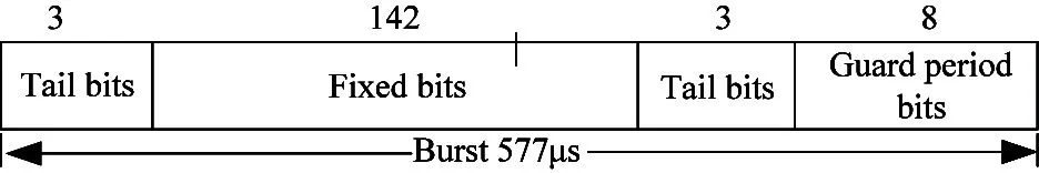
Fig.1 Frequency correction burst structure
Under the ideal condition, the phase of FCCH receiving signal is
(1)
where Ts=1/270.833=3.7μs,and it is a symbol period. But there is a phase error caused by background noise and frequency shift, then the phase of FCCH receiving signal is expressed as
(2)
where Δf is frequency shift, and εn(t) is phase error caused by background noise. Make t=iTs, then the discrete phase of FCCH is
i=0,1,…,141 (3)
i=1,2,…,141 (4)
According to the above two equations, the following equation can be deduced.
i=0,1,…,141 (5)
The phase difference between the two adjacent symbols is determined by the frequency shift and the phase error of the adjacent symbols caused by noise. Here, suppose that the phase error of two adjacent symbols caused by background noise are equal, the following equation can be obtained:
(6)
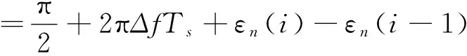
Under an ideal condition, the phase difference of the FCCH’s two adjacent bursts is π/2. In fact, due to the existence of Doppler shift under the condition of high-speed movement, the actually measured phase shift is Δφ(i,i-1). Therefore, the following can be obtained:
(7)
where Δφi,i-1can be obtained through calculation of the actually measured values output by the wireless signal collection equipment, and the calculating procedure is as follows:
According to the I/Q data sequence of the baseband signal output by the wireless signal collection equipment, the phase sequence of FCCH receiving symbols can be calculated:

According to the above phase sequence, the phase difference sequence could be calculated:
Δφ(i,i-1)={Δφ0,Δφ1,…,Δφi,}, where
Δφi,=φi,-φi-1(9)
Putting Δφi,i-1, into Eq.(7),Doppler shift could be calculated.
1.2 Field measurement system
The detailed descriptions of the measurement systems are as follows.
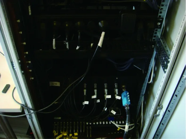
Transmitter: Existing GSM-R base stations (BSs) are utilized as transmitters. The carrier frequency of broadcast control channel of these BSs is in the range of 930.2MHz to 933.8MHz with a bandwidth of 200KHz. The transmitting power is 43dBm and the dual-polarization directional antennas, with 17dBi gain, 65°horizontal, and 6.8°vertical beamwidths are mounted on towers and connected to the signal transmitter with feeder cable. The power splitter with a 3dB loss is utilized to provide multichannel signals for BS to cover the cells on both sides, as shown in Fig.2(a). The transmitting power of BS during the measurement is fixed.
Receiving antenna: The receiving antenna used by the measurement system is an omnidirectional antenna, with 4dBi gain, 80° vertical beamwidth and located in the middle part of the train, on top of the carriage at a height of 30cm above the roof, shown in Fig.2(b). The receiving antenna above the train and the receiver inside the train are connected by a 20m feeder cable with a loss of 3dB.

Fig.2 (a) BS Transmitting antennas (b) Receiving antenna, installed on top of the carriage
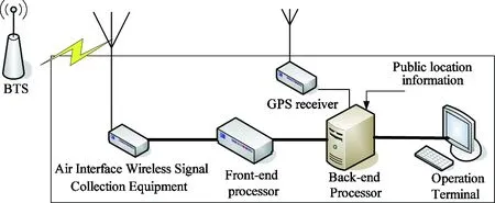
The receiver is the Doppler shift measurement system which can measure the receiving power of the BCCH carrier and gain the FCCH information through demodulation. It is composed of air interface wireless signal collection equipment, front end processor, back end processor, global positioning system (GPS) receiver, operation terminal, GSM-R antenna, GPS antenna and data cable, as shown in Fig.3. We set the BCCH frequency of BS along the railway in the measurement system, then collect wireless signal from these frequency and calculate the frequency shift.
(a)
(b)
The air interface wireless signal collection equipment used here is an 8-channels receiver, which is based on the universal software radio platform (USRP), and consists of the RF processor unit, analog to digital converter(ADC), intermediate frequency(IF) sampler, digital down converter, interface unit, and clock unit, shown in Fig.4. Four sets of the front end processor are installed in the system in order to meet the requirement of processing the signals of 8-channels simultaneously. The algorithm described in 1.1 is realized in the front end processor to analyze and process the data, as well as to obtain the coverage level distribution and the Doppler shift data. The back end processor receives these data from the front end processor, and associates them with the kilometer mark, latitude and longitude information and then stores them. The operation terminal is used for data inquiry and downloading, as well as testing configuration.

Fig.4 Air interface wireless signal collection equipment
1.3 Measurement environment
Extensive measurements were carried out along the section of Zaozhuang West station to Bengbu South station of Beijing-Shanghai high-speed railway in China. Viaduct, cutting and tunnel scenario are included in this section. The train used in the measurement is a high-speed comprehensive testing train, which is 3.8m high and 203m long.
The Doppler shift measurement system is installed in the carriage of the testing train and receives the wireless signal from BS along the track through the receiving antenna deployed on the roof of the train. Under the speed of 0~350km/h, we conducted wireless channel measurement and recorded the receiving power of the BCCH carrier and the FCCH burst in real time. Then the Doppler shift is calculated by demodulating the signal in the front end processor. Over 10 round-trip tests are carried out in this test section so as to collect Doppler shift data under different velocities and ensure the consistency and repeatability of the data.
2 Simulation analysis
Under the condition of HSR, supposing that the distance between BSs is 3000m, the distance between the base station and the railway track is 20m, and without consideration of fading, the Doppler shift can be given by the following equation[17]:
fs(t)=fdcosθ(t)
(10)

(11)
where Dsis half of BS to BS distance, and Ds/2 is the initial distance of the train from BS, and Dminis BS-Railway track distance, both in meters; v is the velocity of the train in m/s, t is time in seconds.
Doppler shift and cosine angle are given by Eqs(10) and (11) respectively, where the required input parameters listed in Table 1 and the simulation result of Doppler shift in different velocities are shown in Fig.5.
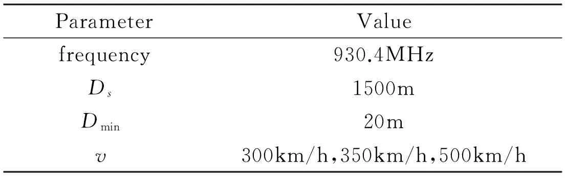
Table 1 Parameters for high speed train conditions
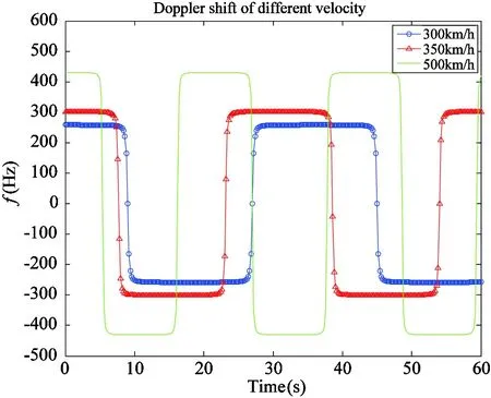
Fig.5 Doppler shift trajectory under different velocities
3 Data analysis
Based on the collected raw frequency shift data (0~350km/h), the distribution of instantaneous Doppler shift, velocity, kilometer mark and coverage level under different velocities are obtained, shown in Fig.6.
Fig.7 and Fig.8 show the distribution trajectory of Doppler shift and velocity in the measured results of 300km/h and 350km/h, respectively. The statistical properties of the absolute value of the instantaneous Doppler shift under speed of 300km/h and 350km/h are shown in Table 2, and the statistical distributions are shown in Fig.9(a) and (b).
Through analyzing the collected data, the Doppler shift distribution laws under the HSR condition can be drawn:
(1) With the increase of the train speed, there is a significant increase in the Doppler shift. When the train speed is below 80km/h, the Doppler shift is about 40Hz~80Hz. When the train speed is 300km/h, the Doppler shift is up to about 250Hz and when the train speed is 350km/h, the Doppler shift is up to 280Hz~300Hz. This is consistent with the theoretical calculation and simulation result in Chapter 2, which verifies the correctness of the Doppler shift measurement and estimation method put forward by this paper.

(a) Doppler shift

(b) Coverage level
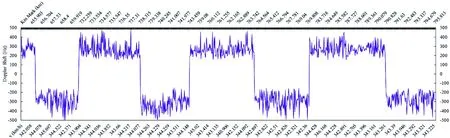
Fig.7 Field instantaneous Doppler shift and velocity distribution (350km/h)
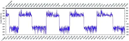
Fig.8 Field instantaneous Doppler shift and velocity distribution (300km/h)
(2) Since the railway mobile communication network is of linear coverage, when the train runs toward the BS direction, the Doppler shift value is positive. When the train-BS distance is much longer than that of the BS-railway track, the Doppler shift maintains the maximum. When the train reaches the BS, the incident wave of the train and the BS is a right angle, and the Doppler shift is 0. When the train passes and runs away from BS, the Doppler shift value is negative, and when the train-BS distance is much longer than that of the BS-railway track, the Doppler shift maintains the negative maximum. In fact, since the BS is very close to the railway track (about 20~40m), and this distance is much shorter than that of the train-BS in most time, the time that Doppler shift value gradually changes from the positive maximum to 0 then to the negative maximum under speed of 350km/h lasts only 2 seconds. It can be seen that this frequency shift changes very quickly, which is consistent to the simulation result.
(3) When inter-cell handover occurs to MS in the high speed train, the serving BS changes. Within the period of handover (around 200ms), the relationship of MS and serving BS changes from back to the incident wave to facing to the incident wave, and the Doppler shift value changes instantly from the negative maximum to positive maximum. That is, the Doppler shift doubles. It can be seen that under such condition, the Doppler shift changes fastest, which is consistent to the simulation result. The rapid change of the Doppler shift results in the increase of the bit error rate (BER) caused by the handover, which results in higher requirement for the frequency shift estimation and correction of the MS receiver.
(4) Due to the multipath effect in the field testing, each path has experienced an obvious Doppler shift process in the relative motion of MS and BS, which leads to fluctuation of the measured instantaneous value within a certain degree.
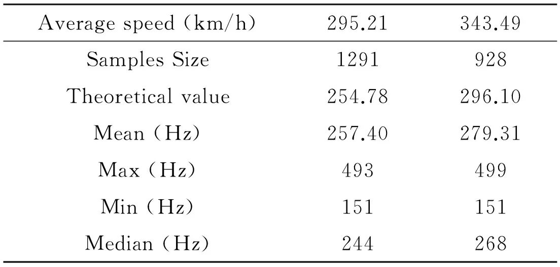
Table 2 Statistical properties of the absolute value of the instantaneous Doppler shift (300km/h and 350km/h)

(a) 300km/h
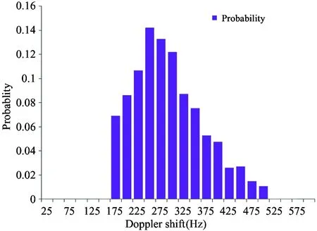
(b) 350km/h
4 Analysis of the impact of Doppler shift on different railway communication systems
For GSM-R system (uplink frequency 885MHz, downlink frequency 934MHz), when the train speed is 350km/h, the Doppler shift is 287Hz (uplink) and 301Hz (downlink), and the corresponding coherence time is Tc=0.423/f=1.47ms (uplink)/1.41ms (downlink)[5]which is far greater than the GSM-R signal’s symbol period (3.69s). That is, the impact of the Doppler shift on the receiver is limited under the speed of 350km/h theoretically. Practically, Doppler shift will bring certain impact on the demodulation performance of BS and MS. The simulation result in Fig.10 shows that the greater the Doppler shift is, the greater the performance loss is[18]. Moreover, under the high-speed condition, the angle of the train and BS is close to zero in the most of the time, the MS-BS distance changes rapidly, so does the frequency shift. Due to the rapid change of Doppler shift, MS may be unable to correctly receive signals from neighboring cells, which is one of the reasons for the handover failure and call dropping. To solve the above problems, it is necessary to adopt and improve the automatic frequency correction technology for BS and MS in HSR.
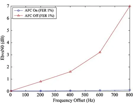
Fig.10 Performance loss caused by Doppler shift
The next generation communication system will adopt the orthogonal frequency division multiplexing (OFDM) technology, which is a high-speed data transmitting technology under the wireless condition[19]. It divides the high-speed data flow into several low-speed data flows to simultaneously transmit on the mutual orthogonal sub-carrier wave, which greatly expands the pulse width of the symbol, improves the anti-multipath fading performance and the anti-delay spread ability. However, due to widening of the symbol’s pulse width, it cannot meet the requirement that Tb is far less than coherence time Tc (Tc=0.423/f) under the high-speed condition. At this moment, the Doppler shift and Doppler spread will destroy the orthogonal characteristic between sub-carriers and bring serious inter-carrier interference (ICI) which decreases the performance of system greatly. Therefore, for the next generation railway mobile communication, further study on the broadband mobile communication system carrier frequency shift estimation and its impact on the system under HSR condition will be of great importance.
5 Conclusion
Doppler shift measurement and estimation are an important means to grasp the time-varying characteristic of the HSR wireless multipath fading channel. This paper presents the Doppler shift measurement based on the phase estimation of the frequency correction channel, which correctly reflects the time-varying characteristic of the channel. A group of 930 MHz Doppler shift measurements under the high-speed condition have been reported and presented for the first time. The consistency (with a difference within 15 Hz) among the actually measured, theoretically calculated and simulated Doppler shift proves the feasibility and accuracy of this method. For the measurement of the broadband wireless channel Doppler shift, this method still needs further improvement to contribute to the reasonable design for the communication system under the HSR wireless multipath fading channel.
In the meantime, based on extensive experimental results, Doppler shift characteristics have been measured, calculated and analyzed. The scientific laws of the Doppler shift distribution of radio channel under high-speed condition are obtained. Frequency shift estimation and correction are important for ensuring the high-speed handover, reducing error rate and signal distortion, which lays a foundation for the establishment of the HSR Doppler power spectrum model and the research and development of the key technology of anti-Doppler shift.
Reference
[ 1] He R S, Ai B, Zhong Z D, et al. Measurement-based stochastic model for high-speed railway channels. IEEE Intelligent Transportation Systems Magazine, 2014, PP (99):1-16
[ 2] Ai B, Cheng X, Kürner T, et al. Challenges toward wireless communications for high-speed railway. IEEE Transactions on Intelligent Transportation Systems, 2014, 15 (5): 2143-58
[ 3] Chen D H. Carrier frequency offset estimation for OFDM in highly mobile channels. Journal of Zhengzhou University of Light Industry (Natural Science Edition), 2012, 27(5): 99-102
[ 4] Liu L Z, Feng D S. Research on measure method of doppler shift. Radio Engineering,2009, 39(5): 51-53
[ 5] Rappaport T S. Wireless Communications Principles and Practice. Second Edition. Beijing: Publishing House of Electronics Industry, 2013. 178-179
[ 6] Bok J, Ryu H G. Path loss model considering Doppler shift for high speed railroad communication. In: Proceedings of the 16th International Conference on Advanced Communication Technology (ICACT), Pyeongchang, South Korea, 2014. 1-4
[ 7] Acosta G, Tokuda K, Ingram M A. Measured joint doppler-delay power profiles for vehicle-to-vehicle communications at 2.4GHz. In: Proceedings of the Global Telecommunications Conference, Dallas, USA, 2004. 3813-3817
[ 8] Acosta G, Ingram M A. Model development for the wideband expressway vehicle-to-vehicle 2.4GHz channel. In: Proceedings of the IEEE Wireless Communications and Networking Conference (WCNC), Las Vegas, USA, 2006. 1283-1288
[ 9] Maurer J, Fügen T, Wiesbeck W. Narrow-band measurement and analysis of the inter-vehicle transmission channel at 5.2GHz. In: Proceedings of the Vehicular Technology Conference (VTC), Birmingham, USA, 2002. 1274-1278
[10] Zhao X W, Kivinen J, Vainikainen P, et al. Characterization of Doppler spectra for mobile communications at 5.3GHz. IEEE Transaction on Vehicular Technology, 2003, 52(1): 14-23
[11] Paier A, Karedal J, Czink N, et al. First results from car-to-car and car-to-infrastructure radio channel measurements at 5.2GHz. In: Proceedings of the 18th Annual IEEE International Symposium on Personal, Indoor and Mobile Radio Communications (PIMRC’07), Athens, Greece, 2007. 1-5
[12] Guan K, Zhong Z D, Ai B. Assessment of LTE-R using high speed railway channel model. In: Proceedings of the 3rd International Conference on Communications and Mobile Computing, Qingdao, China, 2011. 461-464
[13] Li Z M, Xiong Z G, Wu J J, et al. Doppler frequency estimation method based on approximating function under the high-speed railway environment. Journal of Convergence Information Technology, 2012, 7(20):419-428
[14] Yang Y Q, Fan P Y, Huang Y M. Doppler frequency offsets estimation and diversity reception scheme of high speed railway with multiple antennas on separated carriages. In: Proceedings of the 2012 International Conference on Wireless Communications & Signal Processing (WCSP 2012), Huangshan, China, 2012. 1-6
[15] 3GPP TS 45.010 Technical Specification Group GSM/EDGE Radio Access Network, Radio subsystem synchronization (V11.0.0) http://www.3gpp.org:3GPP, 2012
[16] 3GPP TS 45.002 Technical Specification Group GSM/EDGE Radio Access Network, Multiplexing and multiple access on the radio path (V12.1.0) http://www.3gpp.org:3GPP, 2013
[17] 3GPP TS 36.104 Technical Specification Group Radio Access Network, Evolved Universal Terrestrial Radio Access (E-UTRA), Base Station (BS) radio transmission and reception (V12.4.0) http://www.3gpp .org:3GPP, 2014
[18] Huawei Technologies. Method and apparatus for signal processing based on automatic frequency control. China patent: CN101207437A, 2008-06-25
[19] Chen J W. Research on Doppler Shift Estimation Technology in OFDM System: [M.S. dissertation]. Chengdu: Southwest Jiaotong University, 2009. 1-5
Ding Jianwen, born in 1980. He received his M.S. degree from Beijing Jiaotong University in 2005.He also received his B.S. degree from North Jiaotong University in 2002.His research focuses on dedicated mobile communication system for railway, radio propagation and channel modelling, and safety communication technology for train control system.
10.3772/j.issn.1006-6748.2015.02.011
①Supported by the National Natural Science Foundation of China (No. U1334202; 61222105), the Key Grant Project of Chinese Ministry of Education (No. 313006), the Project of State Key Lab of Rail Traffic Control and Safety (No. RCS 2014ZT11).
②To whom correspondence should be addressed. E-mail: jwding@bjtu.edu.cn Received on Sep. 11, 2014, Jiang Wenyi, Zhong Zhangdui, Guan Ke, Ai Bo
猜你喜欢
杂志排行

High Technology Letters的其它文章
- MPLPK: A mobile path localization protocol based on key nodes①
- A method for retrieving soil moisture from GNSS-Rby using experiment data①
- Design and development of real-time query platform for big data based on hadoop①
- Research on suppress vibration of rotor misalignment with shear viscous damper①
- Security analysis of access control model in hybrid cloud based on security entropy①
- Improving wavelet reconstruction algorithm to achieve comprehensive application of thermal infrared remote sensing data from TM and MODIS①