SAR Imaging of Ground Moving Targets with Non-ideal Motion Error Compensation
2015-03-08ZhouHuiZhaoFengjunYuWeidongYangJian
Zhou HuiZhao Feng-junYu Wei-dongYang Jian
①(Space Microwave Remote Sensing System Department,Institute of Electronics,Chinese Academy of Sciences,Beijing100190,China)
②(University of Chinese Academy of Sciences,Beijing100049,China)
③(China Academy of Launch Vehicle Technology,Beijing100076,China)
SAR Imaging of Ground Moving Targets with Non-ideal Motion Error Compensation
Zhou Hui*①②Zhao Feng-jun①Yu Wei-dong①Yang Jian③
①(Space Microwave Remote Sensing System Department,Institute of Electronics,Chinese Academy of Sciences,Beijing100190,China)
②(University of Chinese Academy of Sciences,Beijing100049,China)
③(China Academy of Launch Vehicle Technology,Beijing100076,China)
Conventional ground moving target imaging algorithms mainly focus on the range cell migration correction and the motion parameter estimation of the moving target. However, in real Synthetic Aperture Radar (SAR) data processing, non-ideal motion error compensation is also a critical process, which focuses and has serious impacts on the imaging quality of moving targets. Non-ideal motion error can not be compensated by either the stationary SAR motion error compensation algorithms or the autofocus techniques. In this paper, two sorts of non-ideal motion errors that affect the Doppler centroid of the moving target is analyzed, and a novel non-ideal motion error compensation algorithm is proposed based on the Inertial Navigation System (INS) data and the range walk trajectory. Simulated and real data processing results are provided to demonstrate the effectiveness of the proposed algorithm.
Synthetic Aperture Radar (SAR); Ground Moving Target Imaging (GMTIm); Non-ideal motion error compensation; Doppler centroid
1 Introduction
Synthetic Aperture Radar (SAR) is an advanced imaging sensor, which provides high-resolution images of static scenes. With the increasing demands of both civilian and military industry, Ground Moving Target Imaging (GMTIm) is also becoming an important application to enhance the surveillance capability of modern SAR systems.
Moving targets are defocused and dislocated in SAR images due to their unknown motions. In most existing GMTIm algorithms, the radar platform velocity is assumed to be constant during the data acquisition, and the motion of the moving target is modeled by constant velocity and constant acceleration. In this condition, an algorithm to analyze the optimal and suboptimal schemes for detection and image of ground moving target is presented by Ref. [1]. Ref. [2]also an presented approach to focus moving targets by two-dimensional parameter searching. Ref. [3]has an advanced algorithm to focus the moving target through time-frequency analysis technique in range-Doppler domain. A new approach, to accomplish the azimuth compression of the moving target in range-frequency domain, is presented by Ref. [4]. However, these models above are still unsuitable for the real data processing due to the non-ideal motion errors. Therefore, the applications of these algorithms showed limitations in the real data processing.
In real situation, the non-ideal motion errors come from two sources: the platform and the moving target itself. Ref. [5]has proposed to utilize the Phase Gradient Autofocus (PGA) technique to compensate the residual phase error of the moving target regardless of the forms of the motion errors. However, the PGA technique was just employed to compensate the high-order phase error of the moving target, and it is insufficient in the real data processing since the Doppler centroid of the moving target is also affected by the motion errors.
In this paper, a practical model of the moving target is established concerning on the existence of non-ideal motion errors. Based on this model, the impacts of the platform velocity and the cross-track velocity error on the Doppler centroid of the moving target are analyzed, and a non-ideal motion error compensation algorithm based on the Inertial Navigation System (INS) data and the range walk trajectory is proposed. The energy of the moving target will spread on multiple Doppler centroids if these non-ideal motion errors are not accurately compensated, and they can not be corrected by the PGA technique. Simulated data is utilized to prove the rationality of the non-ideal motion error analysis and the effectiveness of the non-ideal motion error compensation algorithm.
This paper is organized as follows. In Section 2, the echo model of moving targets is described. In Section 3, we analyze the two non-ideal motion errors, which affect the Doppler centroid of the moving target in detail. In Section 4, the proposed non-ideal motion error compensation algorithm is introduced. In Section 5, the simulated data is utilized to illustrate the effectiveness of the proposed algorithm. Finally, some conclusions are given in Section 6.
2 Signal Model
The imaging geometry relationship between the platform and the moving target for broadside SAR is shown in Fig. 1, where the solid line indicates the actual flight path, and the dashed line is a virtual trajectory, conventionally nominated as“the ideal trajectory” or “the nominal path”. In ideal case, the Antenna Phase Center (APC) of the radar moves along the nominal path at a constant velocity[6–9].
Fig. 1 Broadside geometry of the moving target
During the azimuth time intervalTa, the platform flies along the actual flight path fromOtoO1, while the moving target moves fromPtoP1. In order to analyze the echo of the moving target with non-ideal motion errors, the velocities of the platform and the moving target vary with the discrete azimuth timetain our model.Va(ta) denotes the ideal platform velocity;Vx(ta) andVy(ta) denote the along- and cross-track velocities of the moving target, respectively.R0andR(ta) represent the nearest and instantaneous slant ranges between the platform and the moving target, respectively.
The actual and nominal APC position attais [X(ta),Y(ta),Z(ta)]and [Va(ta)ta, 0, 0], respectively. The motion error vector, defined as the displacement between the actual and nominal path, is [X(ta)–Va(ta)ta,Y(ta),Z(ta)], whereY(ta) andZ(ta) denote the motion displacement in the normal plane,i.e., cross-track motion error. Absence of any squint is assumed and the illuminated surface is supposed flat.
Considering a moving point targetP(x0,y0,z0) andP1(x0+Vx(ta)ta,y0+Vy(ta)ta,z0), the instantaneous slant range can be represented asR0is the distance of closest approach with respect to the nominal trajectory,i.e.R0=Letβdenote the off-nadir angle,i.e., the look angle associated with scatter. Then, we havey0=R0sinβ,z0=R0cosβ. Expand Eq. (1) into a Taylor series and keep it to the secondorder term ofta, then Eq. (1) can be approximated as follows
The instantaneous slant range has been separated into four terms in Eq. (2). The first term is the closest distance. The second and third terms indicate the along-track and cross-track motion error caused by the radar platform velocity, while the last term shows the error induced by the moving target velocity. where
After the range compression, the echoes of the moving target can be expressed as
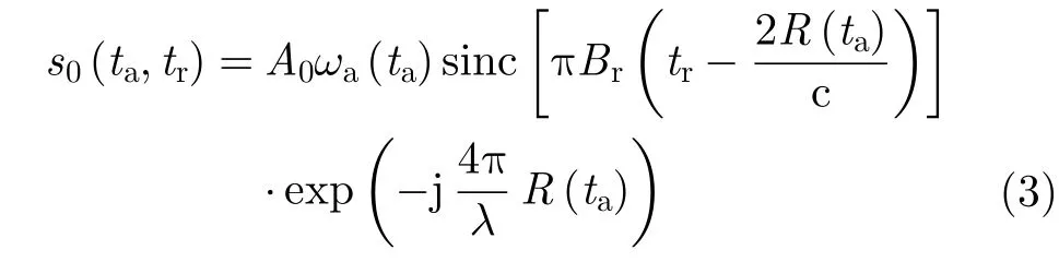
whereA0is the backscatter coefficient of the moving target,ωa(·) represents the azimuth window function,trdenotes the discrete range time,Brandλare the bandwidth and wavelength of the transmitted signal, respectively, and c is the speed of light. Substitute Eq. (2) into Eq. (3), it yields
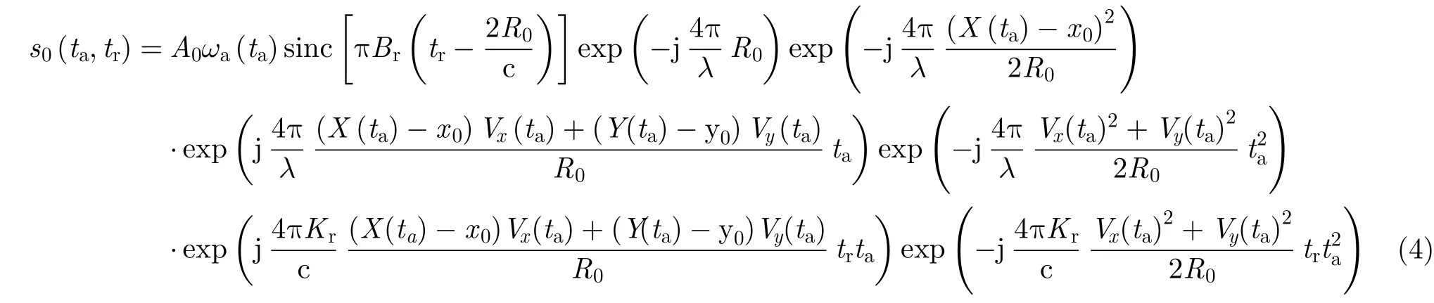
In Eq. (4), the second, third, and fourth exponential terms represent the Doppler centroid and the high-order Doppler phase of the moving target, respectively. The fifth exponential term represents the range walk, and the sixth exponential term represents the range curve. In conventional GMTIm algorithms, in whichVa(ta),Vx(ta), andVy(ta) are assumed to be independent ofta, the Doppler centroid and the high-order Doppler phase of the moving target is the first- and second-order term ofta, respectively. Therefore, after the range cell migration corrected, the moving target can be focused by the estimation values of the first- and second-order Doppler parameters.
SinceVa(ta),Vx(ta), andVy(ta) all vary withtain our model, however, the Doppler centroid might be inconstant, and higher order Doppler phase errors might appear in echo. The highorder phase errors can be compensated by using the PGA technique. As to the Doppler centroid, nevertheless, the PGA technique is ineffective.
If the Doppler centroid of the moving target is not constant duringTa, the energy of the moving target will spread on multiple Doppler centroid, which severely deteriorates the imaging resolution even though the high-order phase errors are accurately compensated. It is noted from the second exponential term of Eq. (4) that the Doppler centroid of the moving target is determined bytaandVx(ta).tais sampled by the Pulse Repetition Frequency (PRF) of the SAR platform, whereasVx(ta) denotes the actual crosstrack motion of the moving target. Therefore, we will analyze the relationship between the motion errors of the platform, the moving target and the Doppler centroid in the next section.
3 Non-ideal Motion Error Analysis
3.1 Platform velocity error
Compensation for the non-ideal motion error of the platform is important in the real SAR data imaging. Due to the air turbulence and the restriction of the platform control system, the platform’s velocity can not maintain constant on a linear course during the data acquisition in most practical situations. The non-ideal motion error of the platform can be classified into two sorts[10]: the non-ideal course that is not a straight line along the azimuth direction and the inconstant platform velocity during the data acquisition. The non-ideal course of the platform can be corrected by the INS data. In the case that INS data is not accurate enough, data-based techniques, such as the PGA, can be adopted to further correct this sort of motion error[11].
In stationary SAR imaging, the platform velocity error will lead to the inconstant Doppler modulation rate. To solve this problem, the SAR system is changed from a time-constant sampling system to a spatial-constant sampling one[12]. The PRF of the spatial-constant sampling system is adjusted to the platform velocity, so as to keep the PRF-to-velocity ratio constant. In such systems, the time-variant PRF can be defined as

whereKvis the PRF-to-velocity ratio. However, as analyzed in Section 2,taaffects the Doppler centroid of the moving target. Given that the azimuth sampling interval is the reciprocal of PRF(ta), the time-variant PRF will result in the errors of Doppler centroid of the moving target.
In the spatial-constant sampling system, the Doppler bandwidth of the clutter can be expressed as
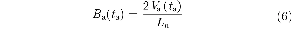
According to Eq. (5) and Eq. (6), bothBa(ta) and PRF(ta) are linear functions ofVa(ta). Therefore, the energy of the clutter in each azimuth sample can be coherently accumulated during the data acquisition. The Doppler centroid of the moving target, which can be expressed as

is independent ofVa(ta). IfVa(ta) is inconstant, the location offdcin each azimuth sample is different from one another, which will make the energy of the moving target spread on multiple Doppler centroids. The impact of the platform velocity error is illustrated in Fig. 2.
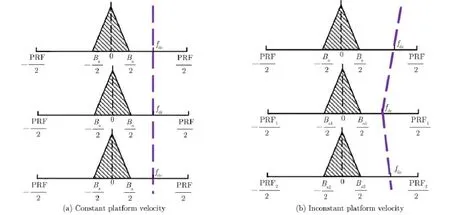
Fig. 2 Impact of the platform velocity error on the Doppler centroid of moving target
In Fig. 2, the purple breaking lines represent the Doppler histories of moving target. In Fig. 2(a), the Doppler history of the moving target is a rectilinear trajectory. On the contrary, the trajectory is not a straight line in Fig. 2(b) with the changes of PRF. In the case of Fig. 2(b), the energy of the moving target can not be compressed into one Doppler centroid. In practical airborne SAR applications, especially for unmanned missions, the platform velocity changes severely in the presence of the air turbulence. Therefore, the platform velocity error must be compensated for moving target focusing[13,14].
3.2 Cross-track velocity error of moving target
In most practical situations, the cross-track velocity of the moving target is not constant during entire data acquisition. According to Eq. (7), the Doppler centroid of the moving target varies with the value of the cross-track velocity. Therefore, if the cross-track velocity is inconstant, the energy of the moving target will spread on multiple Doppler centroids[15,16].
The cross-track velocity error has a significant impact on the Doppler centroid of the moving target. For example, considering a typical Kuband SAR system,λis 0.0194 m,R0is 19000 m, andVais 100 m/s. The Doppler centroid of the moving target can be calculated as

SupposeVxis 10 m/s, thenfdcis 1031 Hz. However, ifVx(ta) varies from 9 to 11 m/s,fdcchanges between 927.9 and 1134.1 Hz. In other words, in the presence of the cross-track velocity error, the moving target can not be focused on a point, even though the high-order phase errors are compensated. Therefore, the cross-velocity error of the moving target must be compensated for real data processing.
4 Algorithm Description
4.1 Platform velocity error compensation
The INS data can be utilized for the platform velocity error compensation. In modern airborne SAR systems, the platform velocity history is recorded by the INS system. With the actual platform velocityVa(ta), the actual PRF history PRF(ta) can be calculated according to Eq. (5).
As to the single moving target imaging, the compensation of the platform velocity error can be considered as a scaling transformation problem. Up to now, we can take compensation under the conditions of non-uniform PRF as a conventional algorithm, especially the GMTIm. PRF might appear uniform in spaceborne SAR system, but impossible in the airborne system. Therefore, in the airborne SAR system, the existing methods are mainly aimed at compensation for forward speed and Line Of Sight (LOS) acceleration and kinds of methods can be used on the basis of different speed of target.
The aim of the correction is to adjust the PRF in each azimuth sample to the same scale. The correction filter in 2-D time domain can be expressed as
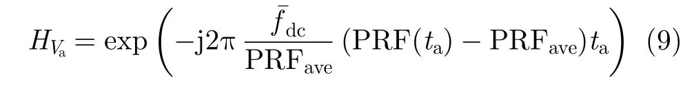
where PRFaverepresents the average PRF, andis the average Doppler centroid of the moving target.can be estimated by the energy balancing method[17].
After the platform velocity error compensated, the platform velocity and the PRF of the system are considered constant, and the residual Doppler centroid error is regarded as the result of the cross-track velocity error.
4.2 Cross-track velocity error compensation
Since the motion of the moving target is not recorded by the system, the actual motion of the moving target should be estimated from the echo. According to the fourth exponential term of Eq. (4), the range walk trajectory of the moving target is affected by the cross-track velocity error. Based on existing processing results of simulations and real data, the range walk trajectory of the moving target with a constant cross-track velocity is a smooth rectilinear figure, whereas the range walk trajectory of the moving target with cross-track velocity error is an irregular curve. Therefore, we estimate the cross-track velocity error from the errors of the range walk trajectory. The principle of our cross-track velocity error estimation algorithm is shown in Fig. 3.
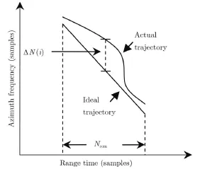
Fig. 3 Principle of proposed motion error estimation algorithm
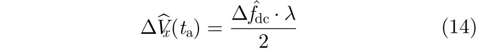
According to the estimation ofthe average cross-track velocitycan be calculated as
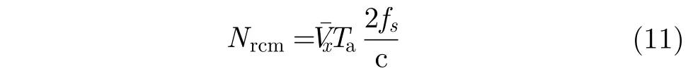
wherefsis the range sampling rate. In Fig. 3, ΔN(i) represents the azimuth shift in thei-th range cell, andi=1, 2,…,Nrcm. By using ΔN, the Doppler centroid error can be estimated as
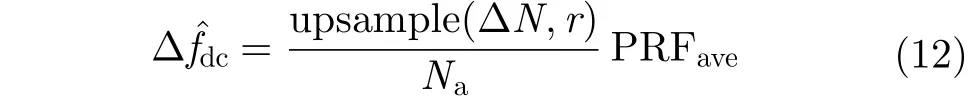
where upsample(x,n) increases the sampling rate ofxby insertingn–1 zero between samples,Nais the azimuth sample number, andris the upsampling rate, which is defined as

With Eq. (12), the cross-track velocity error can be obtained as
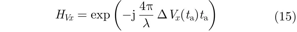
The correction filter of the cross-track velocity error can be expressed as
4.3 Moving target imaging algorithm with nonideal motion error compensation
In this section, the whole moving target imaging strategy with the proposed algorithm is introduced. Based on the proposed non-ideal motion error compensation algorithm above, the imaging resolution of the moving target in real data condition can be significantly improved. The specific processing steps are as follows.
Step 1Correct the non-ideal course of the platform with the INS data.
Step 2Process the range compression and azimuth Fourier transform on the data, and indicate the moving targets in range-Doppler domain. In a single-antenna SAR system, the moving target can be indicated by the clutter filtering algorithm.
Step 3Compensate for the platform velocity error with the INS data.
Step 4Estimate and compensate for the cross-track velocity error of the moving target. With Eq. (14), the actual cross-track velocity of the moving target can be expressed as

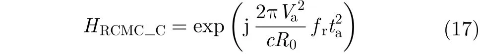
Step 5Correct the range walk of the moving target with Eq. (16). Before the range walk correction, the range curve of the moving target[18–20]can be corrected by using
Step 6Estimate the Doppler modulation rate of the moving target. The moving target can be focused by the Doppler modulation rate estimation.
Step 7Utilize the PGA technique to further compensate for the residual high-order phase error.
Step 8Relocate the focused image of the moving target to its actual location in the stationary SAR image.
5 Experimental Results
In this section, we simulate a typical airborne SAR system with following parameters (see Tab. 1) to validate the algorithm advanced above. A moving target, with the average cross-track velocity of 10 m/s, is located in the center of the scene, and the average velocity on the platform is 100 m/s. Three experiments are performed to validate the two sorts of motion errors, respectively.
Firstly, we simulate the echo data with the platform velocity error. Assuming the platform velocity around 100 m/s, as shown in Fig. 4(a), the imaging results of the moving target without and with the proposed motion error compensation algorithm are shown in Fig. 4(b) and Fig. 4(c), respectively. It notices that, the moving target seriously smear without the compensation,which proves that the platform velocity error deteriorates the focusing results of the moving target as analyzed in Section 3. The azimuth compression results are compared in Fig. 4(d). The broken line represents the azimuth compression result without the proposed algorithm, we find that the energy of the target is compressed into three peaks, corresponding to the platform velocity 95 m/s, 100 m/s, and 105 m/s. On the contrary, with the proposed algorithm, the moving target is focused into its ideal Doppler centroid, as represented by the solid line.
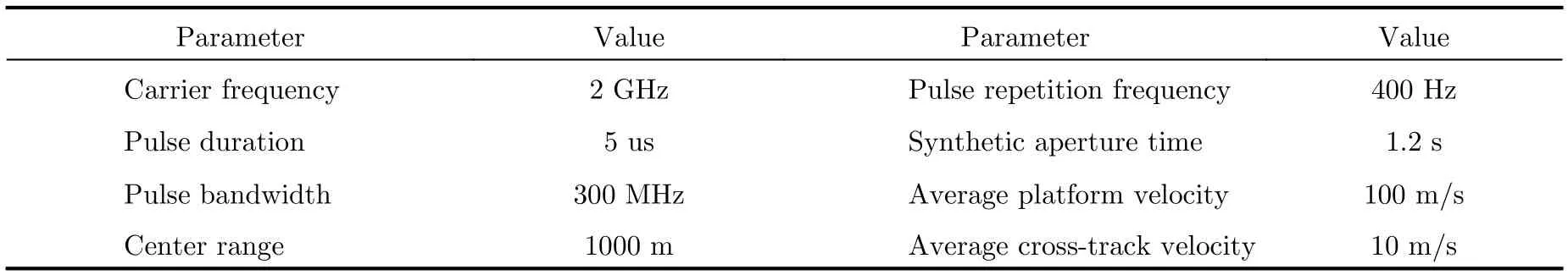
Tab. 1 Simulation parameters
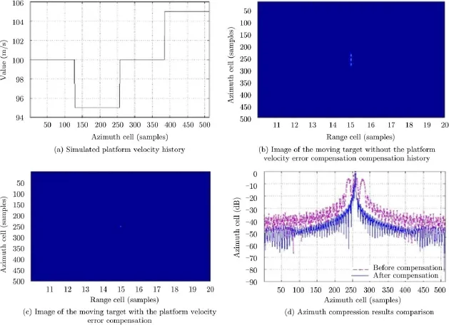
Fig. 4 Simulation of the platform velocity error
Secondly, the moving target with the crosstrack velocity error is simulated. As shown in Fig. 5(a), the cross-track velocity of the moving target is set to change from 9 m/s to 10 m/s. Fig. 5(b) shows the actual and ideal range walk trajectories of the moving target, and it is validated that the range walk trajectory has a corresponding relationship with the cross-track velocity error. The cross-track velocity error estimated by the proposed algorithm is shown in Fig. 5(c). After compensation, the cross-track velocity of the moving target is about 10 m/s, therefore the estimation accuracy of the proposed algorithm is confirmed. Fig. 5(d) compares the azimuth compression results of the moving target with and without the proposed algorithm. According to the broken line, the energy of the moving target is spread on two Doppler centroids as a result of the cross-track velocity error, and the solid line shows that the Doppler centroid error is compensated through the proposed algorithm.
At last, the real X-band airborne SAR data is used to testify the effectiveness of motion error compensation in real applications. One moving target with complicated motions is found in the scene. The real data contains motion error while the data is acquired. Therefore, the imaging of moving target will be smeared without motion error compensation[21,22].
The trajectory of the moving target in range-Doppler domain is shown in Fig. 6(a). It can be seen that the trajectory is not smooth. According to the analysis in Section 3, the imperfect curve results from the inconstant cross-track velocity of the moving target. The platform velocity history obtained from the INS data is shown in Fig. 6(b).The cross-track velocity error estimated by the proposed algorithm is shown in Fig. 6(c). According to Fig. 6(d), the azimuth imaging resolution of the moving target is significantly improved after the motion error compensation with the proposed algorithm, compared with without compensation and compensation with the existing methods (see Subsection 4.1).
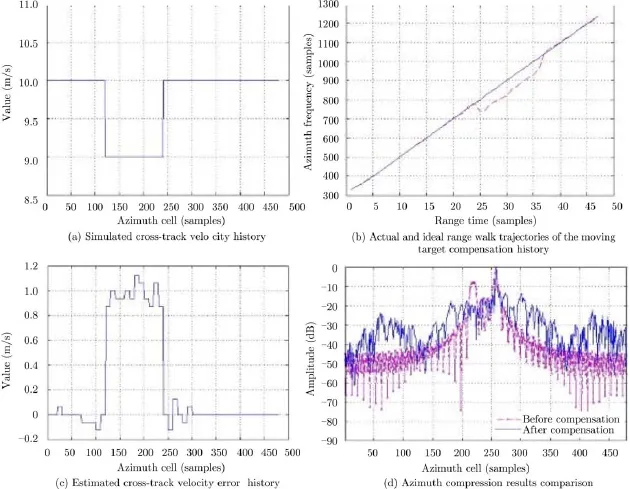
Fig. 5 Simulation of the cross-track velocity error
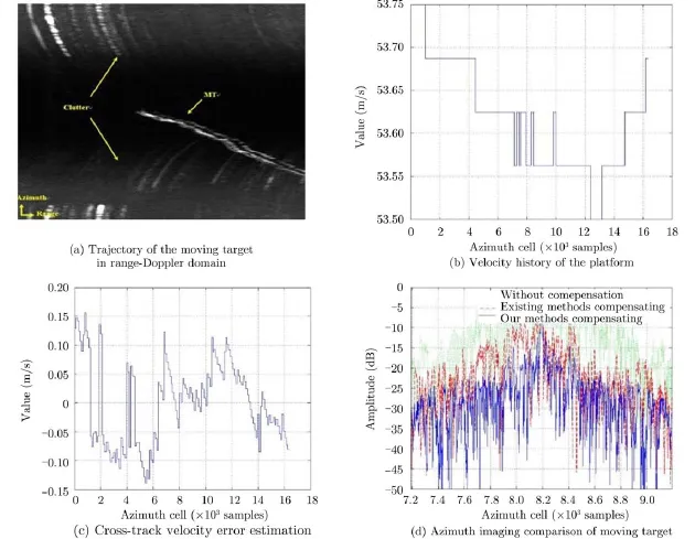
Fig. 6 Imaging of moving target real data with motion error compensation
From the simulations and real data processing results, the validity of the proposed algorithm is finally confirmed.
6 Conclusion
In this paper, we establish a practical model of moving target with considering non-ideal motion errors. Based on this model, the impacts of two sorts of motion errors, the platform velocity error and the cross-track velocity error of the moving target, are analyzed, and a novel motion error compensation algorithm is proposed. Moreover, a moving target imaging strategy with the proposed algorithm is illustrated and the imaging resolution of the moving target in practical applications can be improved. Results of simulation and real data experiments have been employed to verify the effectiveness of the proposed algorithm.
[1]Barbarossa S. Detection and imaging of moving objects with synthetic aperture radar Part 1: Optimal detection and parameter estimation theory[J].IEEE Proceedings-F Radar and Signal Processing, 1992, 139(1): 79–88.
[2]Jao J K. Theory of synthetic aperture radar imaging of a moving target[J].IEEE Transactions on Geoscience and Remote Sensing, 2001, 39(9): 1984–1992.
[3]Tang L, Li D, Wu Y,et al.. Imaging of ground moving targets based on airborne SAR[J].Journal of Systems Engineering and Electronics, 2005, 27(1): 1681–1684.
[4]Zhu S, Liao G, Qu Y,et al.. Ground moving targets imaging algorithm for synthetic aperture radar[J].IEEE Transactions on Geoscience and Remote Sensing, 2011, 49(1): 462–477.
[5]Li Y, Wang Y, and Liu C. Detect and autofocus the moving target by its range walk in time domain[C]. 2011 International Conference on Wireless Communications and Signal Processing (WCSP), Nanjing, China, 2011: 1–5.
[6]Xing M, Jiang X, Wu R,et al.. Motion compensation for UAV SAR based on raw radar data[J].IEEE Transactions on Geoscience and Remote Sensing, 2009, 47(8): 2870–2883.
[7]Wang R, Luo Yun-hua, Deng Yun-kai,et al.. Motion compensation for high resolution automobile FMCW SAR[J].IEEE Geoscience and Remote Sensing Letters, 2013, 10(5): 1157–1161.
[8]Sun G C, Xing M D, Xia X G,et al.. Robust ground moving target imaging using Deramp-keystone processing[J].IEEE Transactions on Geoscience and Remote Sensing, 2013, 51(2): 966–982.
[9]Zhang S X, Xing M D, Xia X G,et al.. A novel moving target imaging algorithm for HRWS SAR based on local maximum-likelihood minimum entropy[J].IEEE Transactions on Geoscience and Remote Sensing, 2014, 52(9): 5333–5348.
[10]Soumekh M. Synthetic Aperture Radar Signal Processing with MATLAB Algorithms[M]. New York, USA: Wiley-Hall, Inc., 1999: 186–230.
[11]Li Y, Liu C, Wang Y,et al.. A robust motion error estimation method based on raw SAR data[J].IEEE Transactions on Geoscience and Remote Sensing, 2012, 50(7): 2780–2790.
[12]Zhang Z. Introduction of Airborne and Spaceborne Synthetic Aperture Radar[M]. Beijing: Publishing House of Electronics Industry, 2004: 27–28.
[13]Yang J, Liu C, and Wang Y F. Detection and imaging of ground moving targets with real SAR data[J].IEEE Transactions on Geoscience and Remote Sensing, 2015, 53(2): 920–923.
[14]Yang J, Liu C, and Wang Y F. Imaging and parameter estimation of fast-moving targets with single-antenna SAR[J].IEEE Geoscience and Remote Sensing Letters, 2014, 11(2): 529–533.
[15]Luo Y H, Song H J, Robert Wang,et al.. An accurate and efficient extended scene simulator for FMCW SAR with static and moving targets[J].IEEE Geoscience and Remote Sensing Letters, 2014, 11(10): 1672–1676.
[16]Lü G H, Wang J F, and Liu X Z. Ground moving target indication in SAR images by symmetric defocusing[J].IEEE Geoscience and Remote Sensing Letters, 2013, 10(2): 241–245.
[17]Li F K, Held D N,et al.. Doppler parameter estimation for spaceborne synthetic-aperture radars[J].IEEE Transactions on Geoscience and Remote Sensing, 1985, 23(1): 47–56.
[18]Yang J G, Huang X T, Jin T,et al.. New approach for SAR imaging of ground moving targets based on a keystone transform[J].IEEE Geoscience and Remote Sensing Letters, 2011, 8(4): 829–833.
[19]Liu B, Yin K, Li Y,et al.. An improvement in multichannel SAR-GMTI detection in heterogeneous environments[J].
IEEE Transactions on Geoscience and Remote Sensing, 2015, 53(2): 810–827.
[20]Li Y K, Wang T , Liu B C,et al.. High-resolution SAR imaging of ground moving targets based on the equivalent range equation[J].IEEE Geoscience and Remote Sensing Letters, 2015, 12(2): 324–328.
[21]Cho B L, Kong Y K, Park H G,et al.. Automobile-based SAR/InSAR system for ground experiments[J].IEEE Geoscience and Remote Sensing Letters, 2006, 3(3): 401–405.
[22]Fornaro G, Franceschetti G, and Perna S. Trajectory deviations in airborne SAR: Analysis and compensation[J].IEEE Transactions on Aerospace and Electronic Systems, 1999, 35(7): 997–1009.

Zhou Hui(1983–) was born in Henan, China. He is currently working toward the Ph.D. degree in the Institute of Electronics, Chinese Academy of Sciences, Beijing, China. His current research interests are in SAR/ISAR signal processing, include ground moving target indication, ground moving target imaging, time-frequency analysis, micro-Doppler effect.
E-mail: zhouhui-lg@163.com
Zhao Feng-jun(1963–) received the M.S. degree from the Graduate University of Chinese Academy of Sciences, Beijing, China, in 1995. Then, he joined the Institute of Electronics, Chinese Academy of Sciences (IECAS), Beijing, China, where he worked on spaceborne/airborne Synthetic Aperture Radar (SAR) system design. He has been the leader of some spaceborne/airborne SAR programs. Currently, he is the Director of the Spaceborne Microwave Remote Sensing System Department, IECAS. His current research interests include spaceborne/airborne SAR system design, ground moving target identification, multichannel SAR signal processing, and circuit design.

Yu Wei-dong(1969–) was born in Henan, China. He received the M.S. and Ph.D. degrees in electrical engineering from the Nanjing University of Aeronautics and Aerospace, Nanjing, China, in 1994 and 1997, respectively. He has been with the Institute of Electronics, Chinese Academy of Science (IECAS) since 1997 and became a Professor of communication and information system in 2000. He has been the Chief Designer for several SAR systems and is currently the Deputy Director of the Department of Space Microwave Remote Sensing System, IECAS. His research interests are airborne and spaceborne Synthetic Aperture Radar (SAR) system design and their signal processing.
Yang Jian(1986–) was born in Liaoning, China. He received the B.S. degree in communication engineering from Harbin Engineering University, and the Ph.D. degree from the Institute of Electronics, Chinese Academy of Sciences, Beijing, China, in 2013. He is currently an assistant researcher with China Academy of Launch Vehicle Technology, Beijing, China. His current research interests include ground moving target indication, ground moving target imaging, frequency-modulated continuous wave synthetic aperture radar signal processing, and motion compensation.
周辉, 赵凤军, 禹卫东, 等. 基于非理想运动误差补偿的SAR地面运动目标成像[J]. 雷达学报, 2015, 4(3): 265–275.
基于非理想运动误差补偿的SAR地面运动目标成像
周 辉①②赵凤军①禹卫东①杨 健③
①(中国科学院电子学研究所航天微波遥感系统部 北京 100190)
②(中国科学院大学 北京 100049)
③(中国运载火箭技术研究院 北京 100076)
传统的SAR地面运动目标成像算法主要集中在距离徙动校正和目标的运动参数估计上。但在SAR实测数据处理中,非理想运动误差补偿对动目标聚焦成像质量至关重要,而且该误差既不能通过固定的SAR运动误差补偿算法来补偿,也无法通过采用自聚焦技术解决。该文根据含有非理想运动误差的SAR运动目标回波信号模型,对影响动目标多普勒中心的两类非理想运动误差进行深入分析,提出一种将INS惯导数据与距离走动轨迹相结合的非理想运动误差补偿算法,并通过实际数据和计算机仿真数据验证了该算法的有效性。
合成孔径雷达(SAR);地面运动目标成像(GMTIm);非理想运动误差补偿;多普勒中心
TN958
A
2095-283X(2015)03-0265-11
10.12000/JR15024
Manuscript received February 11, 2015; revised April 16, 2015. Published online June 15, 2015.
Supported by the National Ministries Foundation.
*Communication author: Zhou Hui.
E-mail: zhouhui-lg@163.com.
10.12000/JR15024.
CLC index:TN958
Reference format:Zhou Hui, Zhao Feng-jun, Yu Wei-dong,et al.. SAR imaging of ground moving targets with non-ideal motion error compensation[J].Journal of Radars, 2015, 4(3): 265–275. DOI: 10.12000/JR15024.