Optimal design and security verification of flying cutterbased on finite element analysis
2014-09-05BoYANJiaLI
Bo YAN,Jia LI
1Shanxi Institute of Mechanical &Electrical Engineering,Changzhi 046011,China;2School of Mechanical Engineering,Tianjin University,Tianjin 300072,China
Optimaldesignandsecurityverificationofflyingcutterbasedonfiniteelementanalysis
Bo YAN†1,Jia LI2
1ShanxiInstituteofMechanical&ElectricalEngineering,Changzhi046011,China;2SchoolofMechanicalEngineering,TianjinUniversity,Tianjin300072,China
The gear sleeve of automotive synchronizer is difficult to process.In this paper,the processing technologies of gear sleeve in the world were introduced as well as the machining principle.The gear sleeve flying cutter cutting mathematical model was established.By means of strength and stiffness analysis,the stiffness is the most important checking target.Special constant stiffness cutting tool of the gear sleeve was designed for numerical control machine,and it is proved that the cutting tool is suitable for cutting.
Flying cutter cutting mathematical model,Structure design,Finite element analysis
Slider groove is the important processing parts in the gear sleeve of automotive synchronizer.Its processing quality directly determines the synchronizer gear sets and even the overall safety performance.However,the surface of the slider groove and the inverted cone are inner,and are in close proximity in processing and there exist a certain manufacturing difficulties.
1.The current situation of the processing technologies for slider groove
At present,the slider groove of auto synchronizer gear sleeve is mostly made by intermittent indexing cutting of form milling cutters in China,with the appearance of new products,the size and specification of slider groove are constantly changing,more form cutters are needed,so that the tool customization,maintenance,and use become a greater burden.And because the form cutter is made of high-speed steel,the cutting speed cannot be too high,the production efficiency will be affected,the grinding and correction of the form cutter are also complicated enough to have a direct impact on the product costs.
In Japan,the United States and other developed countries in the automotive industry,the processing equipment is relatively advanced.Germany is at a leading position.SYNCHROFORM manufactured by PRANEMA can achieve continuous cutting of the slide groove,thus it will greatly improve the processing efficiency and precision[1].
SYNCHROFORM uses a spin processing method on the principle of cycloid,which ensures the continuity of the processing course,and its efficiency is higher than milling under the same process conditions[2].
Nowadays,only two companies in Shanghai and Chongqing use German made equipments to process some parts,the high cost prevents the wide promotion,the technical limitation requires imported tools and programs.Nanjing No.2 Machine Tool Plant has already applied a patent for their imported technology from WERA in Germany[3].
In 2007,Tianjin University and a synchronizer plant co-developed a special CNC machine based on cycloid with independent intellectual property rights[4].The machine can process most slider groove and inverted cone of the auto synchronizer,with the use of locus method,by using a common tool to upgrade,self-programming,it could greatly expand the processing scope and the machining can be promoted to a great degree.
The mathematical model of the flying cutter was discussed in this paper and it also analyzed the finite element structure and safety check of the cutting tool.
2.Flying cutter cutting mathematical model
As shown in Figure 1,the slider groove is a trapezoidal shape,the processing plan is to use a cutter to pass along the slider groove track,while rotating the gear sleeve and the cutter,according to the processing principle of cycloid,their angular velocity ratio is 1∶3.
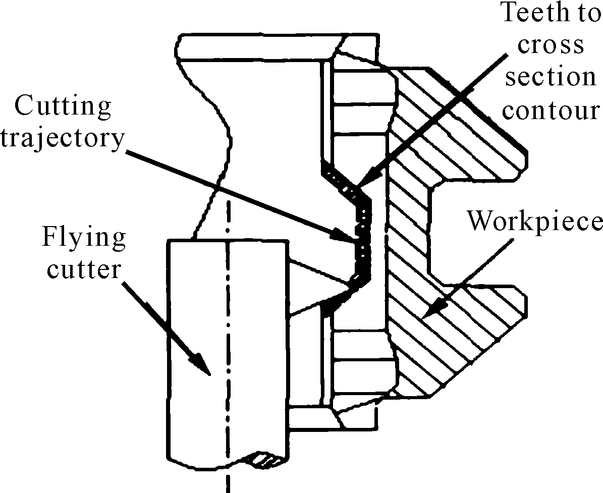
Figure 1.The shape of the slider groove and the cutting track
The flying cutter in this processing is a small interrupted-cutting lathe tool.According to the cutting theory,the main cutting force could be obtained as follows:
(1)
After the experimental design,in which cutting force is measured,and the results were analyzed through multiple linear regression,the slider groove mathematical model could be obtained[5]:
(2)
3.The structural design of flying cutter
The structural design of a flying cutter is composed of the blade shape,the cutting angle,the combination of body and blade,the connection of cutter system and main shaft.
Nowadays,in China the gear sleeve material is mostly 20CrMnTi,this material is typical case-hardened steel with high hardenability,it has a hard and wear-resistant surface and a tough core after carburizing and quenching,it has highly low temperature impact toughness,and the weldability is in medium,the machinability is good after normalization.The processing solution,the cutting speed of the slider groove could be evaluated as follows[6]:
vc=πdn1-πDn2=πn1(3d-D)
The size and structure of gear sleeve parts and structure determine that the cutting speed is at 100 m/min or above,therefore,this flying cutter uses cemented carbide[7].
In order to save time and cost,we chose the indexable turning tool with stable quality,which is common in the market,and then fixed it in a self-designed arbor.
Combining the cutter design and the structure of the slider groove,the Figure 2 could be obtained:
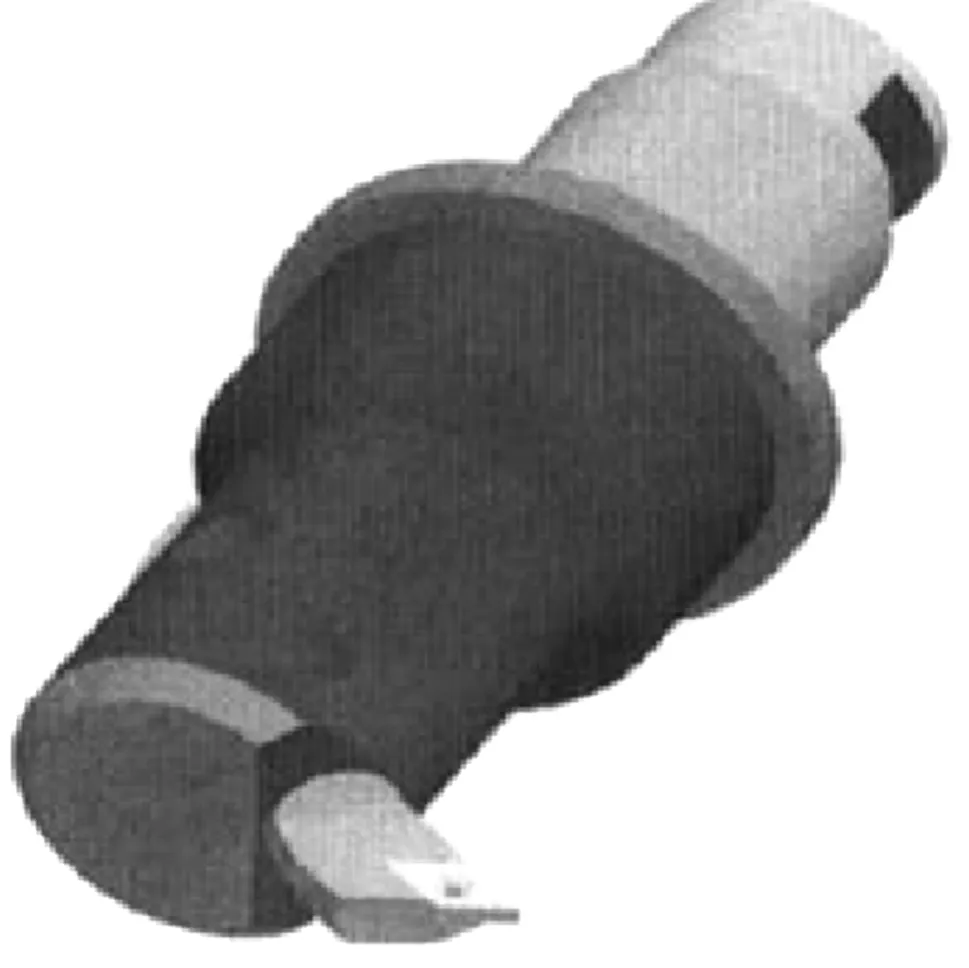
Figure 2.The structure of the flying
1) The choice of blade shape
Since the machining path is a trapezoid line (the angle between the hypotenuse and the bottom is 45°,the wedge angle of the cutter can not exceed 90°,and since the sub- rear corner cannot be too small in order not to increase the friction of the flank surface,the wedge angle of the cutter should not be close to 90°.Since too small wedge angle will cause insufficient rigidity,the wedge angle of the cutter should not be less than 50°.Take the above aspects into consideration,with standard blade sizes for reference,the wedge angle should be 55° or 60°,in other words,the blade should be diamond whose angle is 55° or regular triangle.
2) The determination of the cutter bar diameter
Since there is a wide range of synchronizers and the gear sleeve diameter varies greatly,the shank diameter of the cutter used for process the slider groove varies largely too.As a result,a series of shanks are required to adapt to different diameters.The diameter of the shank in this experiment is Φ32 mm,the inner diameter of the synchronizer gear sleeve is Φ80 mm.
3) A combination of blades and cutter bars
Since the processing of the slide groove is one kind of inner bore processing,which is similar to the boring cutter,the blade could be fixed on the self-made arbor.
4) The location and connection of the cutter bar in the machine tool
As shown in Figure 3,in order to make the location of the cutter bar accurate,a slot was made at the end of the bar in order to use pins through the hole in the cutter shaft to fix it.The bottom section of the slot is a thread connected to the shaft.
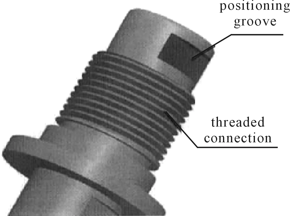
Figure 3.The connected structure of the end
4.The security correction of the flying cutter
The security correction of the flying cutter is necessary,by analyzing such problems as the strength,stiffness and stability of the flying cutter,we were able to understand which element is the weakest link in order to give clear direction to the subsequent optimization.
For the cutter,the cutter shaft was seen as an optical axis in order to simplify the operation.
4.1.Thestrengthcheckofthecuttershaft
The torsional strength condition of the shaft is as follows[8]:
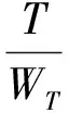
Where,τT(MPa) is the torsional shear stress,T(N· mm) is the maximum torque suffered by the shaft,WT(mm3) is the torsional section modulus of the shaft,d(mm) is the turning diameter at the cutter tip during cutting process,D(mm) is the sectional diameter,[τ]T(MPa) is the allowable torsional shear stress of the cutter shaft material,which should be 35 MPa since the cutter bar is made of 45 steel.Take the relevant data into the above equation,one could obtain:
As we can see,the allowable safe stress of the cutter shaft is much greater than the actual stress,so the strength of the cutter shaft is not the main optimization objective.
4.2.Thestiffnesscheckofthecuttershaft
This shaft can be seen as the optical axis,so the check of torsional stiffness could directly use the formula of mechanics of materials to calculate the deflection or deflection angle:
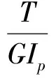
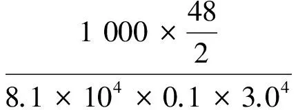
Where,T(N·mm) is the torque suffered by the shaft,Gis the shearing modulus of elasticity of the shaft materials (MPa,for steel,the 8.1×10⁴MPa),Ip is the polar moment of inertia of the shaft section (mm4for round shaft),Lis the shaft length suffering torsion (mm).
The condition of the shaft torsional stiffness is as follows:
φ≤[φ](°/m)
Where,[φ] is the allowable torsion angle of the shaft per meter,related to where the shaft is used.For this shaft (without high accuracy requirement),[φ] can be 1 (° / m).
Take the torque suffered by the cutter into the above equation,one could obtain:
Since the shaft stiffness is also within the allowed range,and they have the same order of magnitude,stiffness could become a more appropriate optimization objective.
It is well known that the nose of the cutter has the maximum deformation and displacement,the displacement of this point will be checked in this paper.Figure 4 is a diagram of the cutter shaft torsion,surfaceAis its fixed end,the cutter is loaded on surfaceBwhose torsional deformation will occur,as shown in Figure 5,from pointBtwist to pointB′.
The displacement of any point on the shaft surface could be calculated as follows:
The surface displacement is used to compare with the result of the cutter optimization design.
The maximum linear displacement of the outer shaft surface is:

This displacement could be used as optimization constraints (linear displacement is allowed).
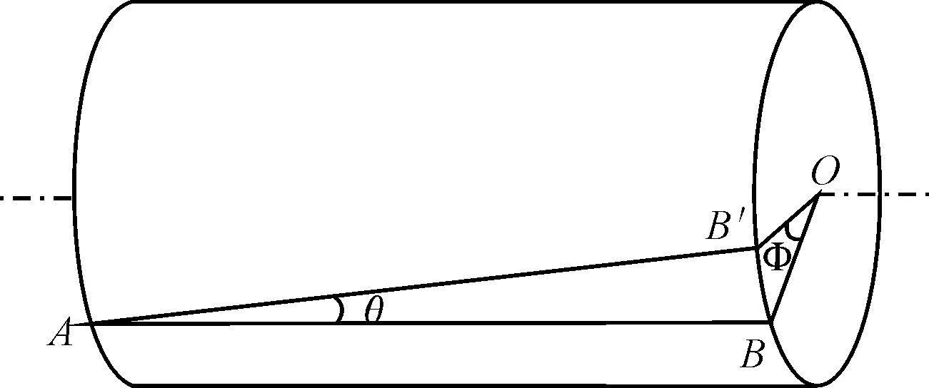
Figure 4.Diagram of the cutter shaft torsion
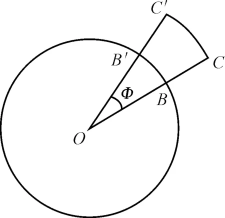
Figure 5.The displacement of any point on the shaft surface
5.The optimization design of the flying cutter
Based on the above obtained results,when the slide groove was cutting,the strength of the flying cutter is sufficient and its stiffness is also in the permissible range,however the security of the stiffness is more prominent.To make the shaft stiffness better,we make optimization design on the shaft structure.
Optimization design is a technology which looks for the optimum design.The so-called “optimum design” refers to a program designed to meet all requirements and whose expenses (such as weight,area,volume,stress and fees) are minimum.In other words,the optimum design is the most efficient one.Any aspect of the designs could be optimized,including the dimensions (such as thickness),the shape (such as the size of the knuckle),supporting position,manufacturing costs,natural frequency,material characteristics and so on.
The optimum structure of the cutter can guarantee the cutting quality and the proper size.The structural optimization design is conducted on the whole cutter.The goal is to optimize the strength and stiffness.
The part analysis in the actual project needs to simplify its structure,and it is very difficult or even impossible for some traditional techniques to deal with some parts with complex shapes.The shaft here can be seen as an optical axis,but the analysis with such a mechanical model will be in a great distance from the actual results,so we use the finite element analysis to achieve the optimization design of the cutter structure.
Finite element analysis can be various,including static analysis,modal analysis,structural vibration analysis (response spectrum analysis,time history analysis).The results could provide all kinds of time curve,data and contour pictures for the engineering design and optimization[9].
The finite element analysis module Pro/mechanica of PRO/E is adopted in this optimization analysis,which could analyze the static and dynamic modal problems in most projects.
After a series of operations such as the properties analysis of the shaft and the cutter material,the constraint conditions,the meshing dividing and some other columns,one could carry out the finite element analysis.It is worth noting that it is necessary to refine the mesh sometimes in order to improve the operational precision.However,Pro/mechanica can not refine the mesh,so simulation accuracy could be improved by increasing the order of the post-processing calculation.
During the cutting process,except for the cutting force,the cutter is affected by its own weight and the inertia force.By the static analysis with Pro/mechanica,one could have a comprehensive and accurate understanding for the tool strength,stiffness and stability under the action of the load determined by each working condition[10].
Based on the results of the displacement and the stress distribution of the tool and the corresponding standards or specifications,the reliability of the tool could be judged.And then it is possible to improve or optimize the design to avoid the damage of some structures or components due to excessive stress and control the overall structure and the stiffness of their components.In this paper,the primary objective is to optimize the cutting degrees of the cutter bar,i.e.,the deformation of the cutter bar.
The static analysis of the flying cutter should include the stress state of all parts,the deformation displacement situation of all parts under the stress.In this optimization,the diameter and length of the front end were treated as the design parameters,the displacement and deformation of the bar surface were treated as the optimization objective,and the restrictions were the strength and stiffness of the bar.The result analysis of the strength and stiffness of the new tool were shown in Figure 6 and Figure 7.

Figure 6.The strength analysis of the tool parts
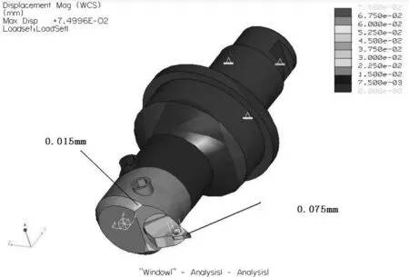
Figure 7.The stiffness analysis of the tool parts
When the static analysis of the tool strength and stiffness meet the requirements,it is also needed to make further analysis of the dynamic characteristics of the tool.Its purpose is to prevent resonance when the tool is cutting.
The flying cutter bears certain dynamic excitation loads during the cutting process.We can use the transient (time history) analysis of Pro / mechanica to determine quantitatively whether the structure can bear these loads and how much the bearing life is.Meanwhile,the dynamic analysis of Pro / mechanica,such as harmonic response analysis,single-point and multi-point response spectrum analysis and random vibration analysis,could calculate the responses of all the components of the tool system in a very easy way.During the cutting process of the flying cutter,the vibration frequency and amplitude should be controlled in a certain range in order not to affect the cutting efficiency.The dynamic analysis of Pro / mechanica can analyze quantitatively the frequency and the amplitude response so that we can determine whether the dynamic structure design of the tool is reasonable.
Affected by many factors,the flying cutter will produce large vibration during the working process.If this excitation frequency is close to the natural frequency of the tool itself,there appears relatively large resonance phenomenon which has a great impact on the cutting quality.So it is necessary to analyze and calculate the natural frequency of the tool.Figure 8 showed the top ten order vibration frequency data and the vibration of the top ten bands chart of the cutting tool through the analysis of PRO/MECHANICA.
Figure 8 showed the first order natural frequency of vibration of the cutting tool with the slide groove is about 2 065 Hz,which differs greatly from the vibration frequency during in the cutting process (in the actual cutting process,the maximum speed of the shaft is 3 000 r/min,the frequency is 25 Hz).Therefore,the possibility of resonance could be ruled out.

Figure 8.The top ten order vibration frequency table
6.Conclusion
This article is intended to design the flying cutter with a slider groove of auto synchronizer gear sleeve,and the processing technologies were comprehensively analyzed.By analyzing the cutting material,calculating the processing conditions and combining the machine structure,a commonly-used cutting tool is designed,and after checking the safety of its strength and stiffness,the weak point has been found.A new flying cutter is obtained through the optimization analysis of the stiffness.Practical tests have confirmed that the strength,stiffness and modal of this tool are all within the safe limit and this optimized cutter has high cutting efficiency and good processing quality[11].
[1]The German Vera Machine Tool Co.Ltd.Machine divided Germany Vera rotation[J].Metal processing world,2006(6).
[2]The Germany SA Ma Ge machine limited company.Rotary splitting machine[J].Automobile Industrie,2004(5):78.
[3]Zhao xiaoming.A synchronizer gear extrusion processing method and tool[S].Chinese patent,200410065486,2005-05-18.
[4]Lijia Yuhuili.One New Machining Method for Gear Sleeve Slots of Automotive Synchronizers[S].Chinese patent,200810056451,2008-05-08.
[5]Zhang yajun,Yanbo.The Mathematical Model of Flying Cutter Cutting of Automobile Transmission Synchronizer Gear Sleeve Slider Groove[J].Machine tool &hydraulics,2008(10).
[6]Yanbo,Zhang guangwei,Cao kewei.Study on Optimization of automobile synchronizer gear sleeve slider groovecutting tools and cutting parameters[J].Journal of Shanghai Univer,2004(8):290-293.
[7]Taiyuan metal cutting tool association.The utility tool technology of metal cutting[Z].2001.
[8]Liu hongwen.Mechanics of materials[Z].1995.
[9]Wang liping,Ye peiqing,Zhanghui,et al.Finite element analysis of deep-hole drill structure based on ANSYS[J].Tool technology,2001(2).
[10]Zhou guofa,Yuujikai,Liuceng.Mass Optimal Design of Autoclave Hoop[J].Pressure vessel,2010(10).
[11]Yanbo,LIjia.Study on Cutting Stability during Flying Cutter Machining the Gear Sleeve of Automotive Synchronizer[J].Machine tool &hydraulics,2011(19).
基于有限元分析的飞刀优化设计及安全校核
闫 波†1,李 佳2
1山西机电职业技术学院,山西 长治 046011;2天津大学 机械学院,天津 300072
汽车同步器齿套的滑块槽属难加工内表面。介绍了滑块槽加工工艺的国内外现状和加工原理,建立了切削滑块槽飞刀的数学模型,设计了加工齿套滑块槽部位的刀具。经过强度和刚度分析,证明刚度问题为首要校核目标。通过优化设计得到基于等刚度原理的飞刀结构,实践检验证明该刀具是适用的。
飞刀数学模型;结构设计;有限元分析
TG721
2013-10-15
† Bo YAN,Associate professor.E-mail:yanbo3610@126.com
10.3969/j.issn.1001-3881.2014.06.020
猜你喜欢
杂志排行

机床与液压的其它文章
- A Sort of fusion control strategy for uncertaintycomplex process with large time lag*
- Design and implementation of a wireless electronic inverterwelding machine*
- Design and characteristic research of double-acting aircraftdeicing fluid pump*
- Preliminary research on the design of flexible barriersfor debris flow
- Numerical simulation of the double suction balance type screw compressor working process*
- Control of EPS with regulating factor