Numerical simulation of the double suction balance type screw compressor working process*
2014-09-05XiaomingWANGQingqingTIANZhongyuHESixiaoLUOGuoliangXIONGChangbiaoWAN
Xiao-ming WANG,Qing-qing TIAN,Zhong-yu HE,Si-xiao LUO,Guo-liang XIONG,Chang-biao WAN
1Mechanical and Electrical Engineering College,East China Jiaotong University,Nanchang 330013,China;2Shenyang RailWay Bureau,Shenyang 110000,China
Numericalsimulationofthedoublesuctionbalancetypescrewcompressorworkingprocess*
Xiao-ming WANG†1,Qing-qing TIAN1,Zhong-yu HE2,Si-xiao LUO1,Guo-liang XIONG1,Chang-biao WAN1
1MechanicalandElectricalEngineeringCollege,EastChinaJiaotongUniversity,Nanchang330013,China;2ShenyangRailWayBureau,Shenyang110000,China
Based on the standardκ-εturbulence model,SIMPLEC was used to solve the N-S equations in this paper,and CFD sliding mesh method was applied to conduct the unsteady numerical simulation on the whole process of double suction balance type screw compressor.The pressure,temperature,velocity,suction and exhaust backflow and eddy distribution of the whole working process,which consist of suction,compress and exhaust,were analyzed.The simulation results provide favorable basis for the screw compressor suction,exhaust design and the optimization of double suction balance type screw compressor.
Double suction balance type;Screw compressor,Unsteady,Sliding meshing,Numerical simulation
1.Introduction
Double-suction balance type of twin screw compressor has two parallel arrangement working chambers,each of them possesses a pair of Yin-screw rotor and Yang- screw rotor,the shape of helical tooth on the same axis is the same,however,the rotation direction is opposite.Between the two working chambers,there is a medium septal part,which plays a role of allowing the above part suction,and then averagely allocate to the two working chambers;in theses two working chambers,compression and exhaust from both sides exhaust ports complete simultaneously[1].Based on the structural characteristics,problem of large axial force caused by structural defects which was faced by traditional screw compressor can be well solved.As the same as traditional screw compressor,double-suction balance type of twin screw compressor is also a kind of displacement compressor whose working volume is in gyroscopic motion,the gas compression depends on the change of volume,while the change of volume depends on the gyroscopic motion of Yin and Yang rotors.So,reasonable disposition of suction inlet and exhaust port will improve the whole working processes including suction,compression and exhaustion.
As the screw compressor working process influenced by many factors,description by using simple equation will lead to big error,so many scholars have done a lot of research in this area.For example,reference[2] introduced some energy analysis results,and established numerical simulation basic equations for this working process.But these mathematical models were limited to their basic assumptions,so it is hard to real numerically simulate the screw compressor during the whole working process.In this paper,CFD sliding mesh technology was applied to the numerical simulation of screw compressor with internal flow field in the working process,this could provide data and example for exhaust optimization design and engineering application,and possesses important practical application value.
2.Governing equation
2.1.Basicgoverningequationsoffluidmotionandheattransfer
The essence of gas flow in screw compressor is the problem of fluid flow and heat transfer,fluid flow is one of the most complicated physical behaviors,as compared with stress analysis in structural design field,the processes of model establishment and numerical simulation are more difficult.However,for any complicated turbulent flow,the N-S equation is proper[3].The governing equations of fluid flow and heat transfer were given in Equations 1~3:
Continuity equation:

(1)
Where,ρis the fluid density;uiis component of fluid velocity along theidirection.
Momentum conservation equation

(2)
Where,pis static pressure;τijis stress vector;ρgiis weight component alongidirection;Fiis other energy item caused by resistance and energy.
Energy conservation equation
(3)
Where,his entropy;kis molecular conductivity;ktis conductivity caused by turbulent transfer;Shis the defined volume source.
2.2.Standardκ-εmodelequation
Standardκ-εmodel is a semi-empirical formula,it is based on turbulent kinetic energy and diffusion rate.The basic equations are shown in Eq.(4) and Eq.(5),respectively[4]:
Turbulent kinetic energyκequation
(4)
Turbulent kinetic energy dissipation rateεequation:

(5)
Where,μlis the laminar viscous coefficient;μtis the turbulent flow viscous coefficient;Gkis turbulent kinetic energy caused by laminar flow velocity gradient;Gbis turbulent flow energy caused by buoyancy force;C1ε、C2ε、C3ε、σkandσεare empirical constants,respectively.
3.Three-dimensional modeling and meshing
In order to simulate backflow and eddy situation in compressor exhaust port,model is divided into five parts,i.e.medium septal part,Yin and Yang rotors,block,exhaust port and gas storage tank.Since the profile of screw compressor is very complex,it is not convenient to model in ANSYS WORKBENCH software.In this paper,PRO/E is used to make three-dimensional modeling,then the well-established model will be imported to ANSYS WORKBENCH through seamless connection.Then contact surface in the MESH wizard will be set up and the type of grid for the tetrahedron unit and the minimum mesh size of 2 mm will be defined.Once the meshing process was completed,the meshed model is shown in Figure1.The total element number is 245 076,and the pitch point number is 1 231 727.
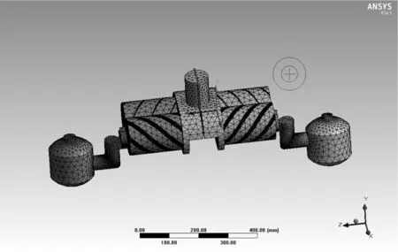
Figure 1.Meshing of the whole screw compressor
4.Boundary condition,Solution control and Compution method
4.1.Boundarycondition
The inlet boundary condition provided by Fluent mainly include velocity inlet,mass flow rate inlet and pressure inlet;and the outlet boundary condition include pressure outlet,outflow,air outlet,ventilator and far field pressure[5].In this paper,the inlet and outlet are pressure inlet and outlet,respectively,and the related pressure and backflow temperature are set up.
Wall surface is used to separate solid region and fluid region,the Yin and Yang rotor wall surfaces were set as moving surfaces,the rotation origin is defined,so does the axis direction and Yin and Yang rotors rotate speeds.The Yin and Yang rotors rotate speeds are 4000 r/min and 6000 r/min,respectively.Apart from,other wall surfaces were set as static wall.
4.2.Equationsolverselection
In this paper,segregated solver is adopted,the discretization schemes of basic equations were all adopted second-order upwind scheme.The solve method was adopted as SIMPLEC algorithm,besides,for the sake of ensuring the coordination among different discrete equations,in this paper by adjusting the relaxation factor to ease the in-coordination of convergence[6].
4.3.Unsteadycomputationmethod
The unsteady computation of screw compressor was accomplished by using the relative sliding mesh between motion region and static region.It is a kind of fully unsteady solution method.Its basic thought is at any time step,the calculation of moving region and static region will be conducted,respectively,and the parameter were passed by interface.With the beginning of the next time step,grid in motion region begins to move,while grid in static region state still.In this time,the grid in both interfaces begins to relative slip[7].
5.Results analysis
Through the numerical simulation on the whole working process of double-suction balance type screw compressor,the pressure contour,temperature contour,velocity contour andXYcontour could be obtained.Analyze these results,the inner pressure,temperature and velocity distribution of compressor could be obviously known.Besides,by the separation analysis of exhaust seat,it could be confirmed whether backflow and eddy appear in exhaust port[8-9].
5.1.Pressuredistribution
In order to understand the whole pressure distribution within the compressor,pressure contour and XY chart could be analyzed.Figure 2 and Figure 3 represented the three dimensional pressure contour andXYchart,respectively.
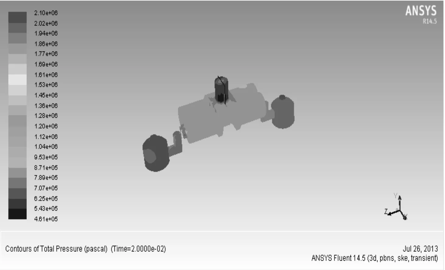
Figure 2.Three dimensional pressure atlas
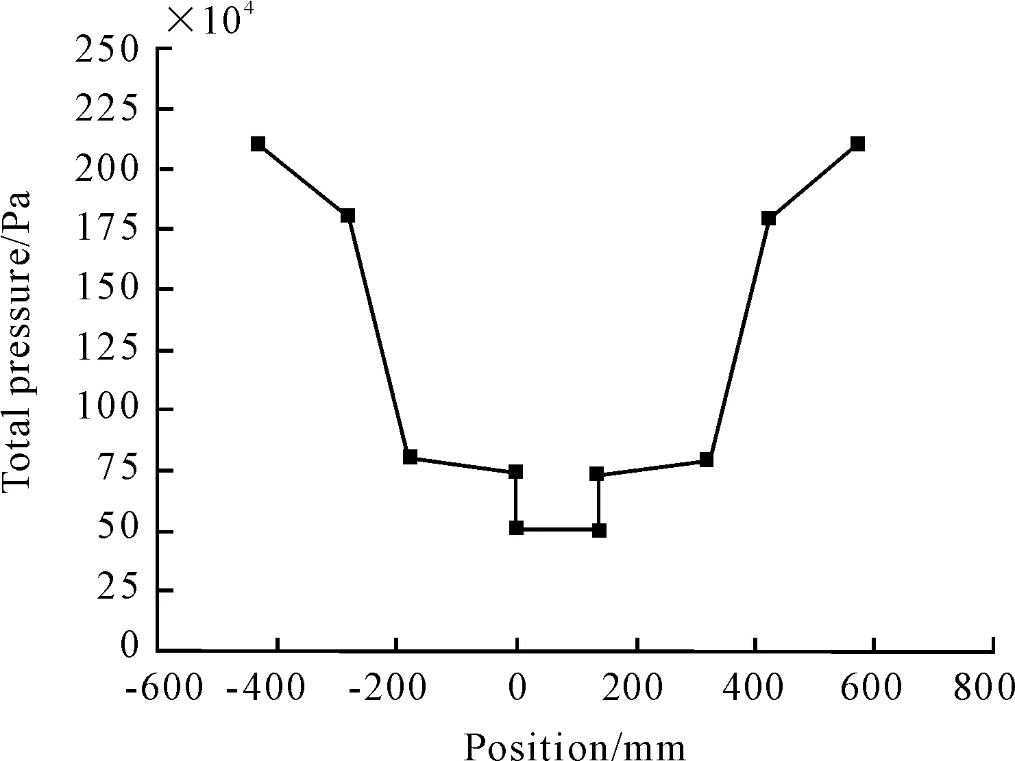
Figure 3.Z=1,pressure distribution XY chart
According to Figure 2,inner pressure was gradually increased from air inlet port to the export of air storage tank.The pressure in air inlet port is 0.5 MPa;inner pressure is about 0.9 MPa,the highest pressure at export of air storage bank could reach up to 2.1 MPa.
According to Figure 3,x-coordinate stands for axial position of every part,y-coordinate stands for total pressure of every part.Figure 3 shows that the inner pressure of suction port to both side air storage export is symmetrically distributed,which coincides with physical truth.The pressure of medium septal part nearly constant,but the pressure of exhaust seat changes greatly,while the pressure of block and air storage bank change slowly.
5.2.Temperaturedistribution
If the temperature of exhaust is too high,the inner lubrication oil might be carbonized,this may lead to compressor poor lubrication and then born out,so it is necessary to analyze the inner temperature of compressor.Figure 4 and Figure 5 show the three dimensional temperature distribution andXYchart,respectively.
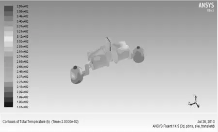
Figure 4.Three dimensional temperature atlas
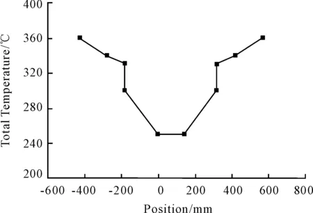
Figure 5.Z=1,temperature distribution XY chart
According to Figure 4,the inner temperature of suction seat to air storage bank export gets increased gradually.When the pressure of exhaust port reach up to 2.1 MPa,the temperature could be greatly improved,the highest temperature could be up to 360 K,the lowest temperature,about 250 K,appears in suction port.
In Figure 3,x-coordinate stands for axial position of every part,y-coordinate stands for total temperature distribution of every part.According to Figure 5,the temperatures of medium septal part are nearly constant,the block temperature change greatly,the change rate of exhaust seat is the biggest.
5.3.Velocityandexhaustportbackflowandeddydistribution
In order to obtain the inner velocity distribution and suction exhaust port backflow and eddy distribution[10],an analysis of total velocity vector diagram and exhaust seat velocity vector diagram were conducted,as shown in Figure 6 and Figure 7.
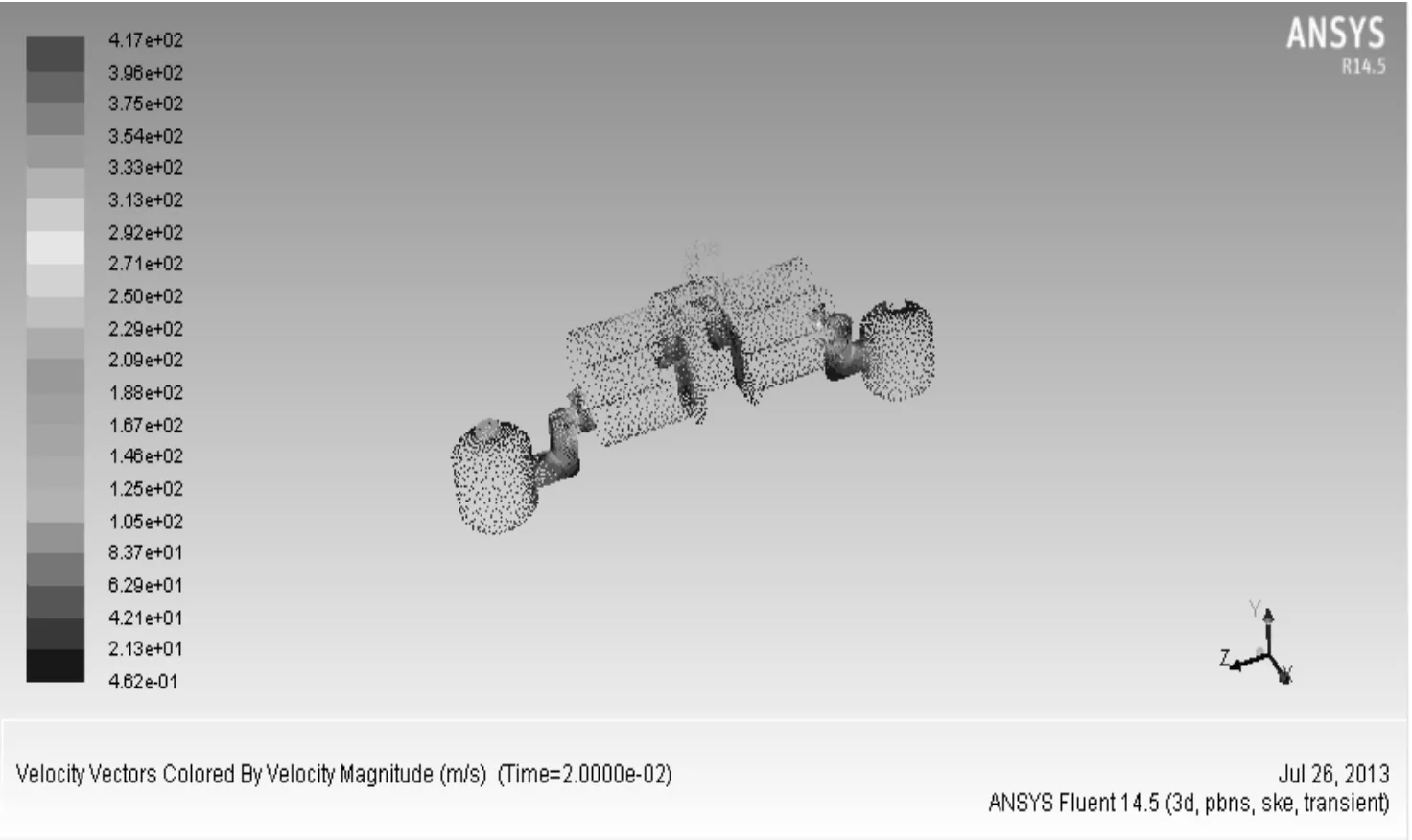
Figure 6.Total velocity vector diagram
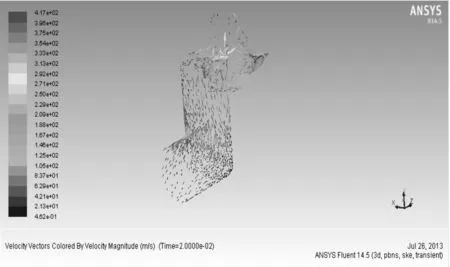
Figure 7.Exhaust seat velocity vector diagram
Figure 6 showed that the distribution of velocity in double suction balance type screw compressor is symmetrical.Air entered from suction port,then flew to Yin and Yang rotors and lastly exhausted port,the biggest velocity could reach up to 417 m-1s,the region with big velocity is near exhaust seat and air storage bank export,this is due to the big compress before entry them,which leads to big velocity.
According to Figure 7,when the pressure of air storage bank reach up to 2.1 MPa,it wil generate big backflow in exhaust seat.Besides,at the corner of exhaust seat,it is easy to form eddy,the reason is that a part of gas outflow from the outlet of compressor,and a part of gas flow from gas storage bank back to exhaust seat,and then eddy could be easily formed.
6.Conclusion
Numerical simulation of double suction balance type screw compressor could really reflect the pressure field,temperature field and velocity field distribution situations of the whole working process of balance type screw compressor.In addition,the analysis of backflow and eddy situations can provide useful data for compressor suction,exhaust design and optimization,and play an important role in promoting the screw compressor numerical design.
[1]Xiao-Ming Wang,Zhi Yang,et al.Design of a new twin-screw compressor based on load balanced configuration[J].Machine Tool &Hydraulics,2012,40(11):81-83.
[2]Si Huang,Guo-mang Yang,et al.Numerical Simulation for Transient Flow in a Rotary Compressor Using Dynamic Mesh Technique[J].Fluid Machinery,2010,38(1):12-15.
[3]Ming-gao Li,Ming Li.Flow Field analysis Technology and Application examples of ANSYS 13.0[M].Beijing: China Machine Press,2012.
[4]Yan-cheng Chen,Zong-huan Guo,et al.Simulation of Flow Field in the Abrasive Water Jet Nozzle[J].Hydraulics and Pneumatics,2012(10):67-69.
[5]Fan Jiang,Wei-ping Chen,et al.Dynamic simulation of flow field inside of lubricate gear pimp[J].Modern Manufacturing Engineering,2007(6):116-118.
[6]Zhan-zhong Han.Fluid simulation calculation example and analysis[M].Beijing: Beijing institute of Technology Press,2009.
[7]Le Hu,Shu-jia Zhang,et al.A numerical study of centrifugal pump using unsteady method compared with steady multi-phase position method[J].Journal of Zhejiang university of Technology,2009,37(6):643-652.
[8]An-na Diao,Ming-zhao Xu,et al.Numerical simulation of Gas in Discharge Chanmber of Screw Compressor[J].Fluid Machinery,2009,37(8):29-33.
[9]Shuo-yuan Wang,Bo Gu,et al.The effect of two-exhaust structure on the efficiency of rotary compressor[J].2007,7(3):77-79.
[10]Ya-guo LYU,Zhen-xia Liu,et al.Numerical simulation of the two-phase flow in external gear pump[J].Lubrication Engineering,2012,37(1):18-21.
摘要:在轴流式血泵的研发过程中,动脉局部流场中可能产生流动剪切率非常低的区域,因此有必要考虑血液的非牛顿特性。建立了轴流式血泵模型,通过CFD仿真分析得到血泵转速和流量的变化对血泵出入口压力分布和速度分布的影响,并采用水和甘油(2∶1)的混合流体替代血液,对设计的血泵进行驱动实验,测量了轴流式血泵输出流量和压力参数。结果表明:所设计的血泵在规律上和仿真是相符的。
关键词:轴流式血泵;非牛顿流体;流场分布;CFD仿真
中图分类号:R318.11
双吸平衡式螺杆压缩机工作过程的数值模拟*
王小明†1,田青青1,贺忠宇2,罗嗣骁1,熊国良1,万长标1
1华东交通大学 机电工程学院,南昌 330013;2沈阳铁路局,沈阳 110000
通过基于标准的κ-ε方程湍流模型,采用SIMPLEC算法求解N-S方程,利用CFD嵌入式滑移网格技术对双吸平衡式螺杆压缩机整机工作过程进行非定常数值模拟。对螺杆压缩机从吸气、压缩到排气整个工作过程的压力分布、温度分布、速度分布以及排气座回流、涡流分布情况进行了分析,从而为双吸平衡式螺杆压缩机排气口设计以及优化提供有利的依据。
双吸平衡式;螺杆压缩机;非定常;滑移网格;数值模拟
TH45
轴流式血泵流场CFD仿真*
谢 雄1,2,谭建平†1,2
1中南大学 高性能复杂制造国家重点实验室,长沙 410083;2中南大学 机电工程学院,长沙 410083
2013-11-06
*Project supported by Technical Personnel Service Firm Action Program of National Science and Technology (SQ2009GJC5005668),Science and Technology Support Program of Jiangxi Province ( 2010BGB00601),University-industry Cooperation Support Program of Jiangxi education department (GJJ10005).
† Xing-ming WANG,Senior engineer.E-mail: wxm2003@163.com
10.3969/j.issn.1001-3881.2014.06.004
杂志排行

机床与液压的其它文章
- A Sort of fusion control strategy for uncertaintycomplex process with large time lag*
- Design and implementation of a wireless electronic inverterwelding machine*
- Design and characteristic research of double-acting aircraftdeicing fluid pump*
- Preliminary research on the design of flexible barriersfor debris flow
- Parameter optimization of electro-hydraulic proportionalsystem of PID based on the improved ant colony algorithm
- Control of EPS with regulating factor