Design and characteristic research of double-acting aircraftdeicing fluid pump*
2014-09-05MiaoGONGZhiweiXINGLiwenWANG
Miao GONG,Zhi-wei XING,Li-wen WANG
1Department of Aeronautical Automation,Civil Aviation University of China,Tianjin 300300,China;2Aviation Ground Special Equipment Research Base,CAAC,Tianjin 300300,China
Designandcharacteristicresearchofdouble-actingaircraftdeicingfluidpump*
Miao GONG†1,2,Zhi-wei XING1,2,Li-wen WANG1,2
1DepartmentofAeronauticalAutomation,CivilAviationUniversityofChina,Tianjin300300,China;2AviationGroundSpecialEquipmentResearchBase,CAAC,Tianjin300300,China
Filling speed of deicing fluid is an important factor that affects the efficiency of airport deicing operation.In this paper,we design a double-acting large flow reciprocating pump for aircraft deicing equipment.We demonstrate the principle,the design drawing and the design calculation of key components.The pressure-flow characteristics of double-acting pump are analyzed through modeling and simulation methods;the optimal program of system damping and flow output are obtained by the simulation experiment of changing piston clearance.We implement a practical experimental analysis,which is based on the optimal parameters obtained from the simulation,to test the rationality of the simulation experiment.The result is shown that,according to the viscosity of the deicing fluid,the system damping,flow and pulsation are optimal relevance and the flow steady output when the piston clearance is 3mm.This verifies the rationality and feasibility of the design.Within the operating pressure range of the pump,the output flow and ripple suppression achieve the desired effect,and the performance is better than the existing similar deicing equipments.This design provides a reference for the related equipment design and industrial applications.
Double-acting pump,AMESIM,Piston clearance,Pressure-flow characteristic,Deicer equipment
1.Introduction
In the process of aircraft deicing operation,filling speed of deicing fluid is the principal element,which directly affects the efficiency of deicing operations.Currently,several major north airports have built a kind of large deicing fluid filling system that consist of a stationary fluid filling and ratable matching station and mobile high flow fluid filling station[1].In deicing fluid filling system,the efficiency of the whole system is directly affected by the speed of filling pumps.The system need several large flow pumps working together,and the physical characteristics of deicing fluid require that the pumps would not generate shear force to deicing fluid during the operation because it can cause some loss of fluid viscosity.Furthermore,using bottom filling hole for filling the large mobile deicing fluid station requires the pumps having definite pressure resistance.Moreover,the filling pump is expected to lower the pulsation of outputting flow to enhance the real time mixing ratio accuracy of deicing fluid and water.The lower output pulsation can also reduce the resonance between the mobile fluid filling station and the pipeline to keep stability of system[2].
To achieve these requirements,we designed a large flow and high performance double-acting deicing fluid filling pump.Through modeling and simulation,we verified the feasibility of design and analyzed the performance parameter of the pump,and then we found out the optimal configuration among damping clearance and output ripple,which was tested by experiment.This paper can provide the basis for high-performance deicer equipment design and manufacturing.
2.Design principles of double-acting aircraft’s deicing fluid pump
2.1.Designgoals
The main component of the deicing fluid is propylene glycol or ethylene glycol,together with a small amount of anti-corrosion agents,antifoam agents,antioxidants,flame retardants,stabilizers and the like[3].The fluid can be achieved with a different freezing point and refractive index by mixing different proportions of water.It’s required filling to deicing vehicles or mobile fluid stations rapidly.According to above requirements,the design goals are stated as follows:
① The pump should not produce shear stress on the fluid molecules in the filling process which affects the physical and chemical characteristics of deicing fluid;
② Pump cavity is made of stainless steel;
③ Maximum flow of pump>30 m3/h;
④ Maximum bear pressure>0.5 MPa.
2.2.Designprinciples
According to these requirements,we designed a double-acting piston-type deicing fluid pump.The cavity is made of 304 stainless steel.The structure principle diagram is shown as Figure 1.
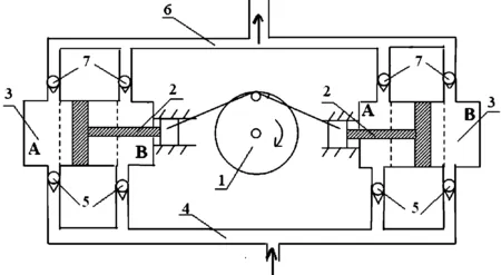
Figure 1.Double-acting deicing fluid pump structure principle diagram
Two same built plunger pump cylinders(3) are linked by a crank connecting rod (1) via piston(2),the fluid inlet pipeline (4) connects with fluid inlet check valve(5) on each plunger pump cylinder,the fluid drain pipeline (6) connects with drain check valve(7) on each plunger pump cylinder.The plunger pump cylinder is divided into two zones (A and B).Each zone has two check valves.Considering the corrosion caused by the deicing fluid,the plunger pump cylinder (3),the fluid inlet pipeline (4) and the fluid drain pipeline (6) is made of stainless steel materials.
The working process is introduced as follows.First,start the power source (after turning on the power),crank link mechanism drive two cylinder pistons reaching the limit position of the right side (dashed line) then move to the left,the piston moves to the left so that the deicing fluid in zone A is pushed,meanwhile,the inlet check valve of zone A is closed and the drain check value of zone A is opened,the pressure pushes the fluid out of the drain check.At the moment the cylinders in zone B become vacuum,the pressure of the inlet pipeline is greater than the cylinders inside,pushing the fluid through inlet check valve into zone B,meanwhile,the drain check valve in zone B is closed.When the pistons reaches the limit position of the left side (dashed line) then move to the right,the working principle is exactly the same.When the drain check valve of both zones is opened,the deicing fluid will be pushed out quickly at a certain pressure.Crank link mechanism drives the piston for reciprocating linear motion in this way.The processes of suction and drainage are continuous.The two cylinders at left and right sides suck up and drain deicing fluid twice respectively in a working cycle.This working form can effectively ensure the continuity and stability of filling.
3.Design and calculations of key components
3.1.Powerconversion
The maximum working pressure:
p=0.5 MPa=0.5×10⁶N/m2
Volume flow (single cylinder flow):
Q0=20 m3/h=20×0.000 277 m3/s
Pressure unit dimension:L-1MT-2
volume flow unit dimension:L3T-1
Power unit dimension:L2MT-3
Calculation according to the dimension as follows:
(L-1MT-2)×(L3T-1)=L2MT-3
The result of the calculation above is same as the power unit dimension,so the effective power output for unilateral pump is:
P1=p·Q=2.777 kW
The effective power output for bilateral pump is:
P2=2P1=5.554 kW
When the motor output power is 11 kW and the output flow remains the same,the instantaneous maximum output pressure can be up to 1MPa[4].
3.2.Calculationsofthetransmissionratio
We set piston diameter asD,the piston radius asR,the schedule of length asL,the pump flow asQ,the reciprocating frequency of the pump asf.Then we choose double-acting plunger pump piston diameterD=150 mm,the linear motion of the piston strokeL=120 mm,motor speedn=1 400 r/min.The calculation is as follows.
The design volume flow (unilateral pump flow):
Q0=20 m3/h which can be converted to 0.333 3 m3/min
The flow of a double-acting plunger pump piston once reciprocating is:
Q1=2πR·2L=0.075×0.075×3.1415×0.12×2=0.004 24 m3
So the flow of a double-acting plunger pump piston once reciprocatingQ1is 0.004 24 m3.
The pump reciprocating frequency of one minute is:
f=Q0÷Q1=0.333 3÷0.004 24=78.6
The transmission ratio between the motor and the pistons is:
i=n/f=1 400÷78.6=17.81
3.3.Designcalculationsofkeyparts
The static bearing capacity under rated pressure and flow is known that the rated pressure is 0.5 MPa and unilateral pump design flow is 20 m3/h.We set the axial force in piston cylinder asF,the radius of the bolt asR1,the piston rod radius asR2,the tensile strength as t,the crank pin radius asR3.
We choose bolt radiusR1=9 mm,the piston rod radiusR2=12 mm,crank pin radiusR3=15 mm.
Maximum axial force of piston in cylinder is:
F=0.075×0.075×3.141 5×0.5×1 000 000=8 835.729 N
Maximum piston cylinder axial force is approximately equal to 883.572 9 kg.
We choose the materials of the piston rod and bolts are both of 304stainless steel,which has 150 MPa tensile strength;the material of crank pin is 40Cr which has 800 MPa tensile strength and 500 MPa shearing strength.The axial tensile strengthFin piston cylinder is decided by cylinder head tightens bolts cross-sectional area and the piston rod minimal cross section.The verifying calculation is as follows:
The maximum tension of a single bolt (total four) can withstand is:
F0=R12×π×t
So:F0=0.009×0.009×π×150×1 000 000=38 170 N
The maximum tension of the bolt group is:
F1= 4F0=152 680 N
The maximum tension of the bolt rod is:
F2=R22×π×t
That is:F2=0.012×0.012×π×150×1 000 000=67 858 N
The maximum shear-force of turn pin:
F3=R32×π×t
So:F3=0.015×0.015×π×500×1 000 000=353 429 N
It is known thatF1,F2,F3are all greater than the maximum axial bearing capacity of the cylinderF.Therefore,axial tensile forceFin the piston cylinder which is 8 835.729 N is under safe limits,even if the axial force in the movement increases seven times.
The power transmission is designed by a belt speed shift and a gear speed shift.Then it drives the eccentric sheave to rotate.The power transmits through crank pin of the eccentric sheave,then transfer to piston rod for reciprocating motion.The first stage belt speed shift is consisted of a large belt wheel on axle-1 and a small belt wheel on motor.Diameter of small wheel is designed to be 100 mm,and 410 mm for the diameter of large wheel.So the first transmission ratio is 4.1.The second gear shift stage is consisted of a small gear on axle-1 and a large gear on axle-2.Teeth number of small one is designed as 18,and 74 for big wheel,so the second transmission ratio is also 4.1.
The two stage gear ratio is first stage ratio multiplied by the second ratio which is 16.81.Motor speed is 1 400 r/min,the transmission ratio is 16.81,the reciprocating piston frequencyf1=83.28,f1>f.Therefore,the output flow will be greater than the theoretical side 20 m3/h,the bilateral will be greater than 40 m3/h.
3.4.Generallayoutschemeofdouble-actingdeicingfluidpump
We demonstrate the general layout scheme of double-acting deicing fluid pump base on the above design and calculations,as shown in Figure 2.
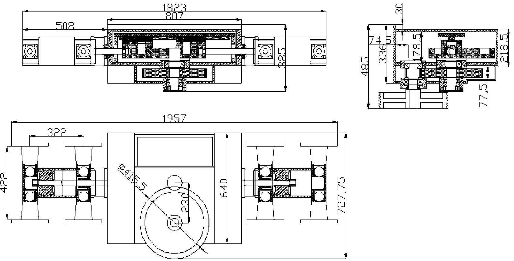
Figure 2.General layout scheme of double-acting deicing fluid pump
4.Modeling and simulation
4.1.Modelconstruction
The deicing operation requires that the double-acting deicing fluid pump can output huge flow in specific pressure range.At present,typeⅠaircraft deicing fluid is frequency-used which is mainly consisted of propylene glycol.Its viscosity coefficient is higher so the output flow of reciprocating pump will produce larger pulsation.We adopted the software AMESIM[5] to simulate and model,so that we can validate the feasibility of the design and find out the best configuration of high performance case,then we can analyze the optimum parameters of damping clearance for reducing the flow ripple on the premise of guaranteeing rated flow.AMESIM is based on the concept of “basic element”,that is,extract the smallest unit of engineering system from all models which allows the user to describe the function of all systems and components in the model without writing any program codes,it allows users liberate from the tedious mathematical modeling to focus on the design of the physical system[6-7].
Figure 3 is AMESIM simulation model of double-acting deicing fluid pump.The speed after reducing is included in the motor simulation data;crank linkage corresponds to the actual eccentric wheel mechanism.The initial phase of two cylinders and the phase difference can be set in the parameter setting;block of hydraulic cylinder,ball valve and combination of weight modules correspond to the reciprocating pump cylinder;safety valve corresponds to the actual safety valve;throttle valve corresponds to the actual ball valve.During the simulation,12 different size diameter of the ball valve were input as batch parameters;by changing the piston clearance to find the optimum damping solution.
As shown in Figure 3,the two modules in upper left corner of the figure are used to set the physical parameters and the inertial parameters of the medium.
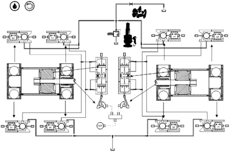
Figure 3.AMESIM simulation model of double-acting deicing fluid pump
4.2.Settingsofmodelparameters
The main parameters of the model are shown in Table 1 which is according to the design plan.
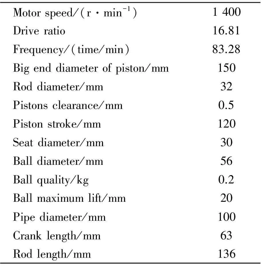
Table 1.The main parameters of the system
The ambient temperature of model is 20℃,the atmosphere is standard,typeⅠaircraft deicing fluid is the simulation fluid whose main component is propylene glycol.The main parameters of fluid are shown in Table 2.
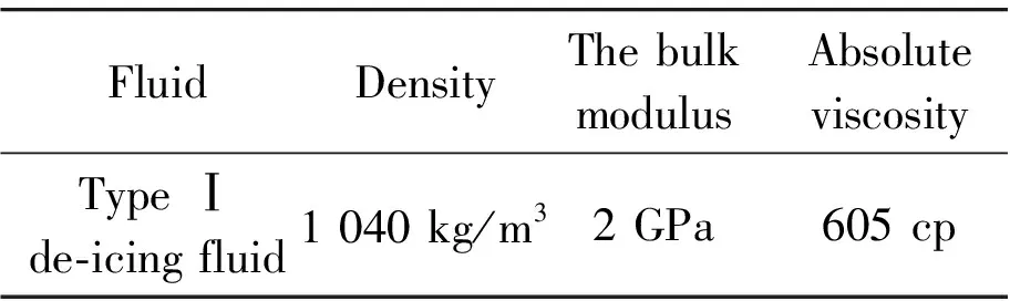
Table 2.Fluid physical parameters
Throttle valve internal structure was simulated with SolidWorks.We calculate the area under different angles respectively,and calculate the equivalent diameter according to the cross-sectional area.The calculation process is shown in Figure 4,and the equivalent diameter of sectional area is shown in Table 3.
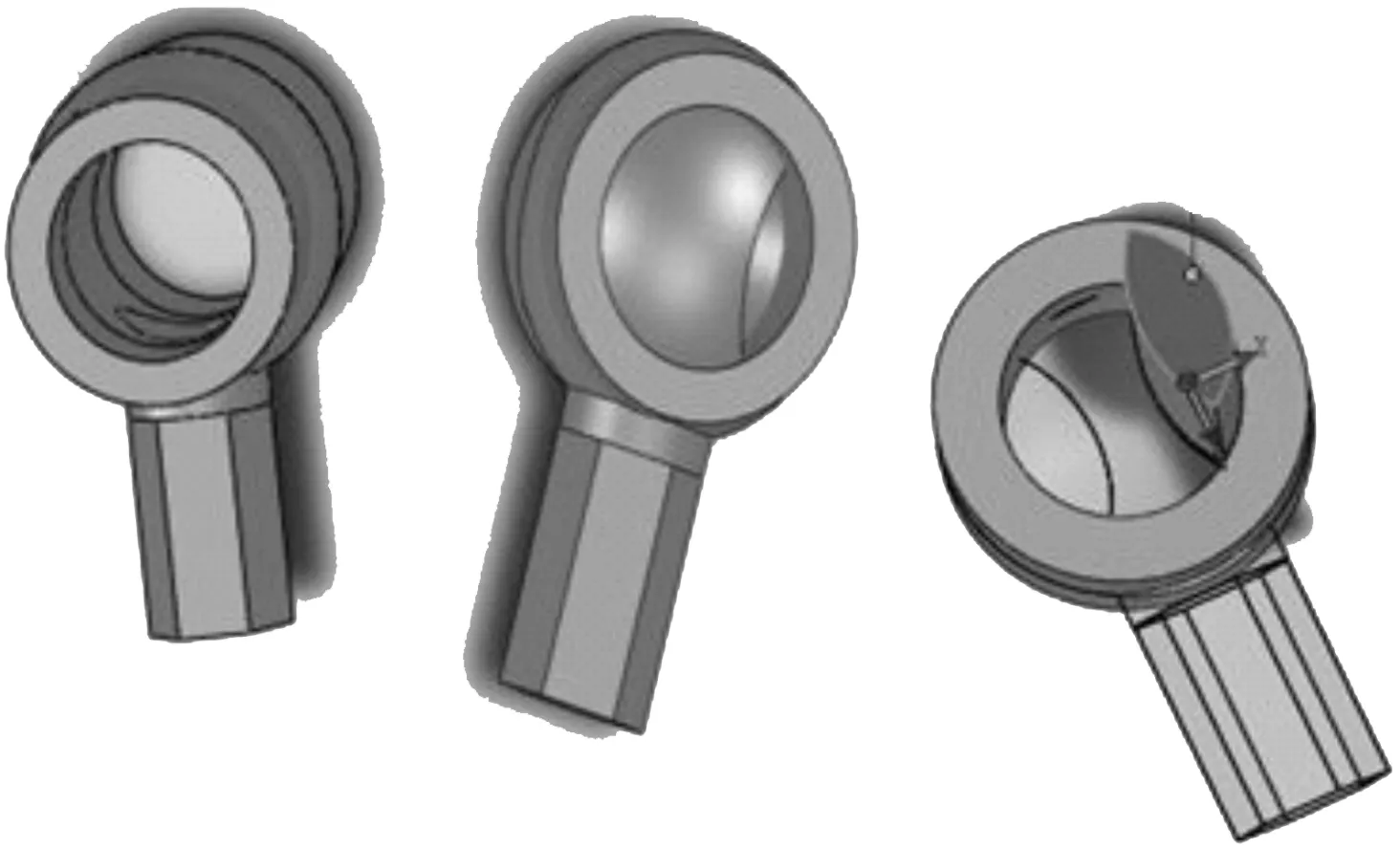
Figure 4.Calculation process of valve opening area
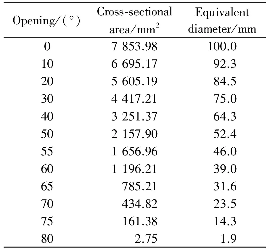
Table 3.The equivalent diameter of the flow area of throttle
4.3.Simulation
We start the simulation according to the parameters settings of the system model building and simulation running and the selection of sub models.After the simulation operation,we can calculate the average flow rate and average pressure value in front of ball valve by the post-processing function of AMESIM[8].Considering the pipe friction,we set pipeline model as compressible friction model.When the simulation medium is typeⅠdeicing fluid and the piston clearance is 0.5 mm,the system average flow curve and average pressure curve are shown respectively as Figure 5 and Figure 6.
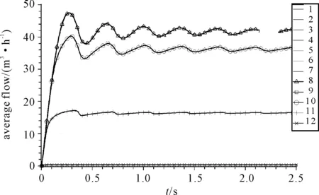
Figure 5.The average flow curve
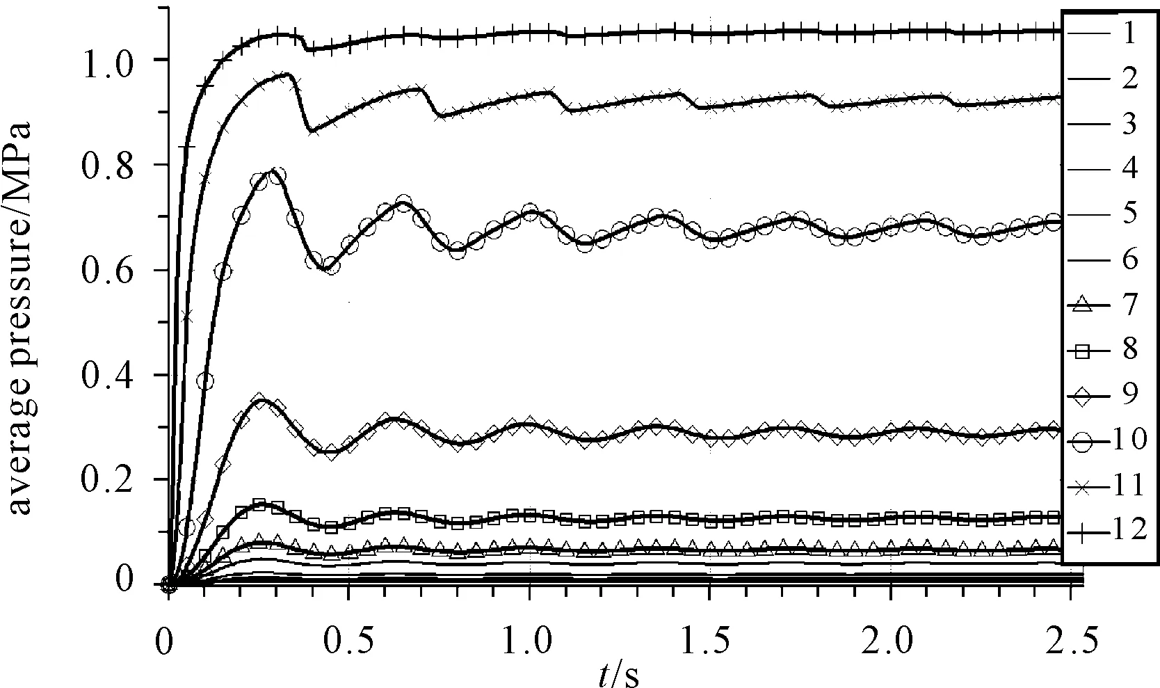
Figure 6.The average pressure curve
According to the simulation results,we obtain the relation curve of the average flow and the average pressure,as shown in Figure 7.
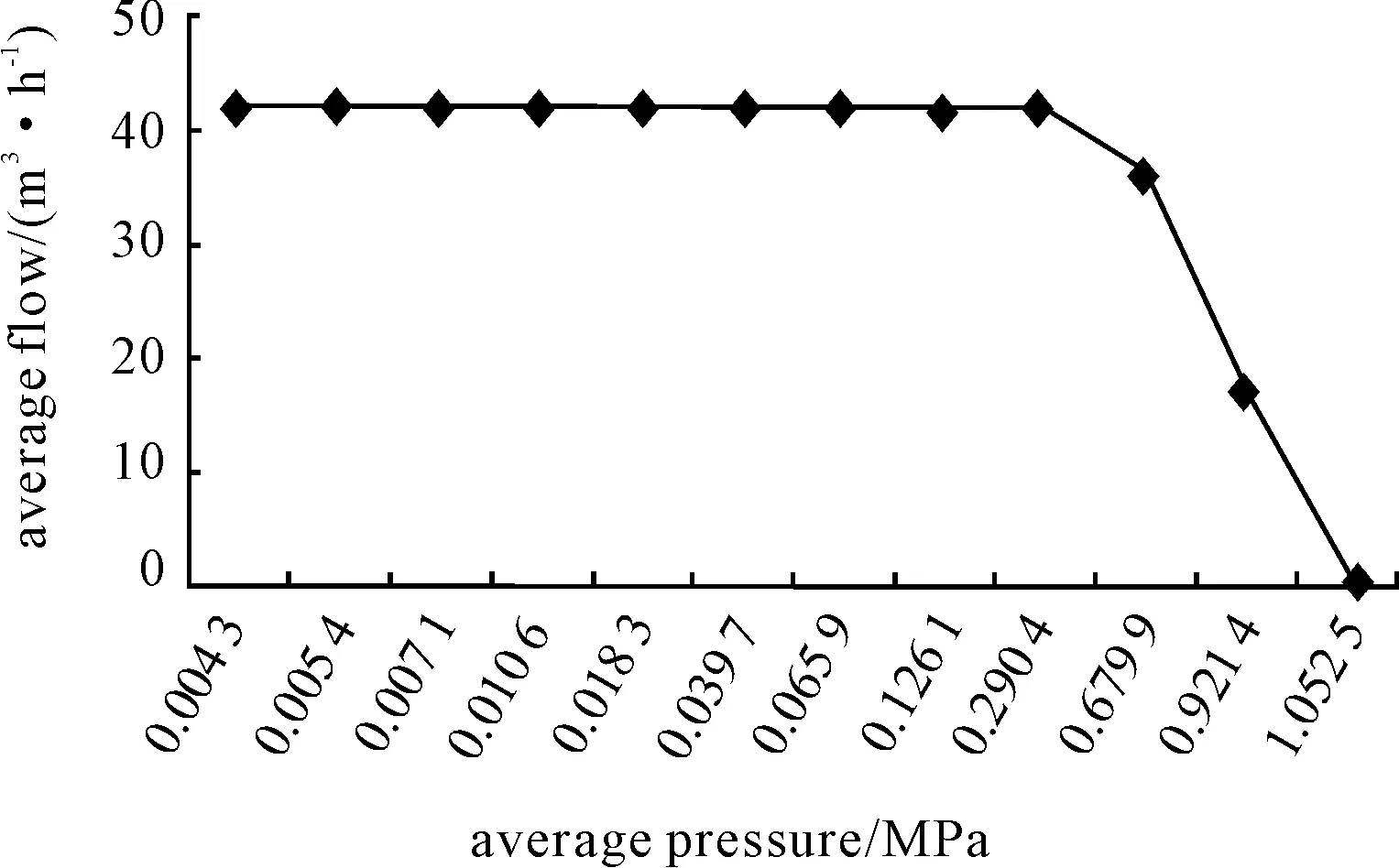
Figure 7.The average pressure-flow curve
The results is shown that the output flow peak of the double-acting pump within the scope of 0.000 43 to 0.290 4 MPa is 44 m3/h after running stability,and it is greater than the maximum flow of design,inside leakage in the pump is smaller.When the pressure is between 0.290 4 to 0.679 9 MPa,the flow has a slow decrease trend.The flow is still 35 m3/h or more,when the pressure below 0.679 9 MPa,the pump shows good performance parameters.The output flow and continuity is superior to traditional single-acting reciprocating pump.
In order to further optimize output flow pulsation of system,considering the larger viscosity properties of deicing fluid,we adjust the piston clearance from 0.5 mm to 1.0 mm,1.5 mm,2.0 mm,2.5 mm and 3 mm respectively,then we do modeling and simulation respectively,analyze the damping effect of the piston clearance[9-10] changes on the system.Considering the maximum working pressure of mobile fluid station charging is about 0.041 5 MPa (this typical data comes from deicing Fluid Filling System of BCIA),the six condition of valve opening is most close to the actual operation.We intercept the flow simulation curve of pump from 45 to 50 seconds,at this time it has run into stable output,as shown in Figure 8.
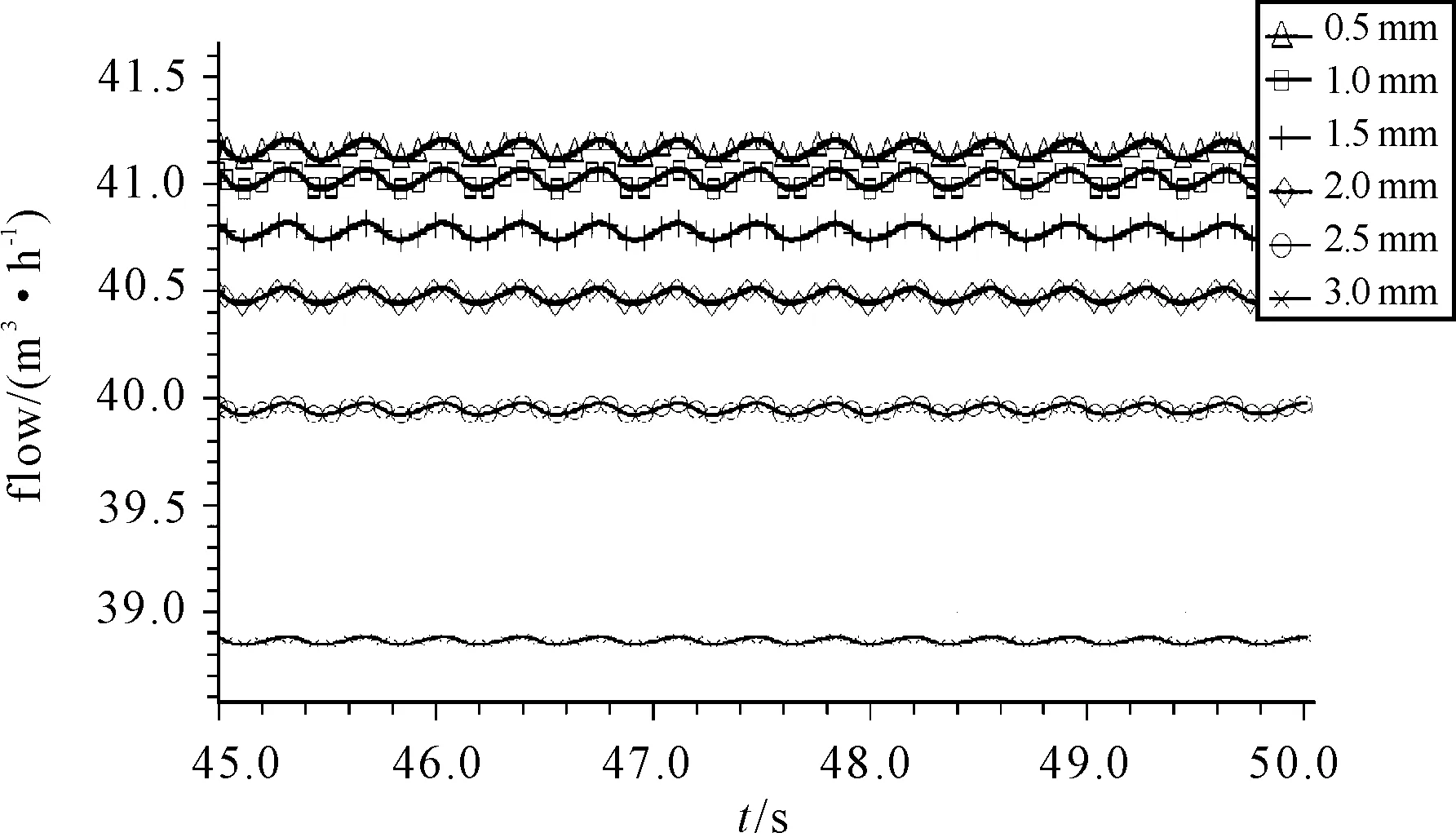
Figure 8.The flow curve under different piston clearance
The curve indicates that with the gradual increase of piston clearance,the system average flow,average pressure and flow fluctuations are slow downward.Simulation measures that the system damping and flow parameters achieved in a relative optimal configuration when the piston clearance is 3 mm.By system calculations,the output flow pulsation is reduced to 0.198 6 m3/h,it’s better than the other 5 piston clearance conditions.
We capture the average pressure-flow curve point at 3 mm piston clearance,as shown in Figure 9.Due to high viscosity of deicing fluid,the flow can still reach 31.42 m3/h when the pressure value is 0.532 MPa,the performance of pump still exceed the design requirements.Under this condition,although the output flow reduces some,it can still meet the design flow.The pulsation decreased and the output showed better continuity;the resonance between pipe system and mobile deicing fluid station can be reduced effectively,the decrease of pulsation may promote more accurate of real-time mixing ratio for deicing fluid and water.

Figure 9.The average flow-pressure curve of 3 mm piston clearance condition
5.Experiment
According to the simulation results,the actual piston clearance is made for 3 mm to test,as shown in Figure 10.Pressure sensor is installed in the pipeline behind throttle valve and flow sensor is installed in export pipeline.The pressure and flow data of difference process in system is collected and transmitted into computer through AD board.We calculate the average value of each point after removing interference data.Then we obtain the pressure-flow curve as shown in Figure 11 and the output flow curve of typical work condition as shown in Figure 12.
It is shown in the experiment that the pressure-flow curve tendency of experiment is coincident with the simulation.Contrasting with Figure 7 and Figure 9,owing to some inevitable internal leakage in actual working condition,the experiment flow is lower than the simulation.When the pressure ranges from 0.017 7 MPa to 0.023 4 MPa,the internal leakage is mainly caused by the retaining valves of suction.When the pressure is above 0.023 4 MPa,the mechanical seal of retaining valve is enhanced along with the accretion of pressure,it cause the flow curve rising,the flow is at peak of 36.1 m3/h when the pressure is 0.042 4 MPa,under this condition,system leakage is at the fewest point.Considering the normal working pressure of actual filling system is about 0.041 5 MPa (BCIA data),the flow of pump is desirable.According to the performance of pump,it can meet the expected value for actual working well.
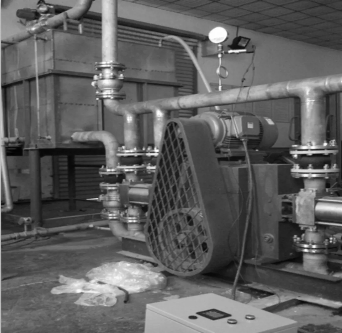
Figure 10.Photo of experiment
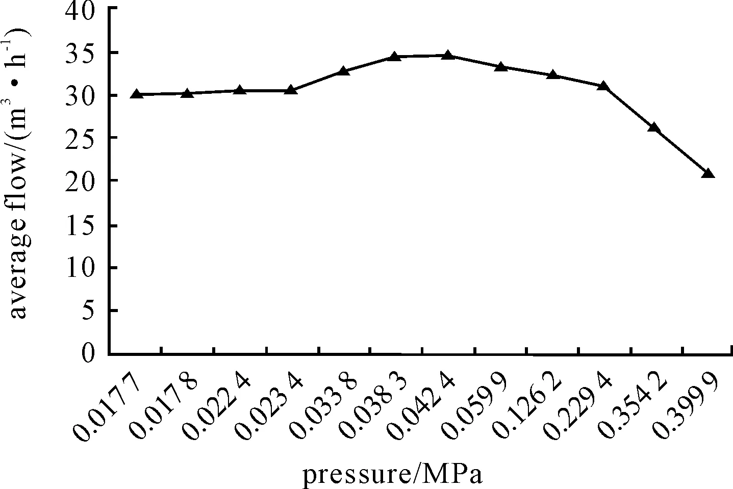
Figure 11.The average flow-pressure curve of experiment
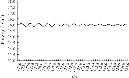
Figure 12.The average flow curve under 0.424 MPa condition of experiment
According to the simulation,we choose the pressure condition of 0.042 4 MPa to analyze the output flow pulsation of system.As shown in Figure 12,the average flow curve of experiment is under the condition of type Ⅰ deicing dynamic viscosity,3 mm piston clearance.By calculations of computer,we obtain that the output flow pulsation is within 0.231 2 m3/h and the output flow has good continuity.The result testified the experimental validity of simulation and showed that the increase of piston clearance has a damping effect on output flow.According to the experiment,the maximum flow can reach 36.1 m3/h,which is 1.8 times than the same level reciprocating pump from market.It is shown that the double-acting pump has good performance parameter,can meet the demand of high flow and stable filling for large mobile deicing fluid station.
6.Conclusion
1) In order to enhance the efficiency of aircraft deicing operation,we designed a double-acting large flow reciprocating pump which is aimed at aircraft deicing fluid viscosity characteristics and requirements of deicing operations.We demonstrated the detailed design calculation and the overall design drawing.
2) By AMESIM modeling and simulation,we analyzed the pressure-flow characteristics of the pump,it is shown that the pump performance parameters can meet the design expectation and commendably satisfy the requirements of deicing operation.The simulation results testified the reasonability of design.
3) By the simulation experiment of changing the clearance of the piston,it is shown that on the premise of guaranteeing output flow,the increase of piston clearance can eliminate flow pulsation to some extent.We implemented the practical experiment based on the optimum parameters of the piston clearance from the simulation experiment.The result is shown that according to typeⅠdeicing fluid,when the piston clearance is 3 mm,the system damping,flow and pulsation are optimal relevance,flow steady output.It verified the rationality and feasibility of the design.
[1]Qin Zhanggao,Xing Zhiwei,Gao Qinji.Research of civil aircraft deicing technology[R].2005-2006.Beijing,airport department of CAAC.2005.
[2]Chen Bin,Xing Zhiwei,Wang Liwen.Research of Pipeline Pressure Control Method for Aircraft Deicing Vehicle[J].Machine tool and hydraulics,2009,08:129-131.
[3]MH6001-2000,Deicing/anti-icing fluid for aircraft(ISO Type I )[S].Beijing:Civil Aviation Administration of China,2000.
[4]Practical handbook of physics[M].FuJian: the practical handbook of physics workingteam,1991:970-989.
[5]Chen Bo.Modeling and simulation research of hydraulic impactor based on AMESIM[D].Shanghai: Shanghai University of Engineering Science,2012.
[6]Wang Xiaoyu.Modeling and simulation of impactor of hydraulic roofbolter based on AMESim[C].2013 International Conference on Renewable Energy and Environmental Technology,2013,448-453: 3426-3429.
[7]Quan Long,Yang Yang,Hou Xuwei.Simulation and experimental research on the axial piston pump with series three-windows in valve plate[J].IEEE,2011:71-76.
[8]Ou Subei,Wang Lianguo.Numerical analysis of seepage flow characteristic of collapse column under the influence of mining[J] International Journal of Mining Science and Technology,2013(23):237-244.
[9]Bowers,Walter J,Olson,et al.A capacitive probe for measuring the clearance between the piston and the cylinder of a gas piston gauge[J] .Review of Scientific Instruments,2010,81( 3 ): 102-110.
[10]Kajikawa H,Ide K,Kobata T.Precise determination of the pressure distortion coefficient of new controlled-clearance piston-cylinders based on the Heydemann-Welch model[J].2009,80:101- 111.
摘要:飞机服役于沿海环境中,各部位极易受到盐雾等腐蚀性气氛的影响。通过盐雾试验对机载电子设备机箱涂层进行耐蚀性检测,利用扫面电镜、电化学工作站,红外光谱等方法对涂层进行分析,研究其在盐雾条件下的失效机理及退化规律。结果表明:涂层在盐雾环境下的失效主要是由于物理过程,而非化学老化导致,且涂层失效过程主要包含3个进程,用交流阻抗谱对其整个腐蚀过程可以精确地表征。
关键词:复合涂层; 盐雾试验; 交流阻抗
中图分类号:TH86
双作用式飞机除冰液泵设计及特性研究*
龚 淼†1,2,邢志伟1,2,王立文1,2
1中国民航大学 自动化学院,天津 300300;2中国民航航空地面特种设备研究基地,天津 300300
除冰液的加注速度是影响机场除冰作业效率的重要因素。设计了一种面向飞机除冰装备领域的双作用式大流量往复泵,给出了设计原理、主要部件设计计算书及总体设计图。通过建模仿真分析双作用泵的压力流量特性;通过改变活塞间隙的仿真实验得到系统阻尼和流量输出的折中优化方案,并依据仿真得到的最佳参数进行实验,验证仿真分析的合理性。结果表明:根据除冰液的粘度,活塞间隙在3 mm条件下,系统阻尼、流量、脉动到达最优关联,流量输出平稳,验证了设计方案的合理性和可行性。泵在工况压力范围内,输出流量和脉动抑制均达到预期效果,性能超越现有同类除冰加液设备性能,为行业应用和相关设备的设计提供参考。
双作用泵;AMESIM;活塞间隙;流量压力特性;除冰设备
TH112
盐雾试验对电子设备机箱涂层的影响
鞠成玉†,王晓慧, 朱 润, 任晓明
北京航空航天大学 可靠性与系统工程学院,北京 100191
2013-10-06
*Project supported by the Joint Funds of the Natural Science Foundation of China and Civil Aviation Administration of China (Grant No.60939001) and National Key Technology Research and Development Program of China (Grant No.2012BAG04B02)
† Miao GONG.E-mail:mgong@cauc.edu.cn
10.3969/j.issn.1001-3881.2014.06.010
杂志排行
机床与液压的其它文章
- A Sort of fusion control strategy for uncertaintycomplex process with large time lag*
- Design and implementation of a wireless electronic inverterwelding machine*
- Kinematics analysis of cleaning robot for aircraft surfaces based on screw theory*
- Preliminary research on the design of flexible barriersfor debris flow
- Numerical simulation of the double suction balance type screw compressor working process*
- Control of EPS with regulating factor