Wind-wave induced dynamic response analysis for motions and mooring loads of a spar-type offshore floating wind turbine*
2014-06-01MAYu马钰HUZhiqiang胡志强XIAOLongfei肖龙飞
MA Yu (马钰), HU Zhi-qiang (胡志强), XIAO Long-fei (肖龙飞)
State Key Laboratory of Ocean Engineering, Shanghai Jiao Tong University, Shanghai 200240, China, E-mail: yuma@mit.edu
Wind-wave induced dynamic response analysis for motions and mooring loads of a spar-type offshore floating wind turbine*
MA Yu (马钰), HU Zhi-qiang (胡志强), XIAO Long-fei (肖龙飞)
State Key Laboratory of Ocean Engineering, Shanghai Jiao Tong University, Shanghai 200240, China, E-mail: yuma@mit.edu
(Received March 11, 2013, Revised July 29, 2013)
Due to the energy crisis and the environmental issues like pollution and global warming, the exploration for renewable and clean energies becomes crucial. The offshore floating wind turbines (OFWTs) draw a great deal of attention recently as a means to exploit the steadier and stronger wind resources available in deep water seas. This paper studies the hydrodynamic characteristics of a spar-type wind turbine known as the OC3-Hywind concept and the dynamic responses of the turbine. Response characteristics of motions and mooring loads of the system under different sea states are evaluated and the effects of the loads induced by the wind and the wave on the system are discussed. The calculations are carried out with the numerical simulation code FAST in the time domain and the frequency analysis is made by using the FFT method. The results and the conclusions from this paper might help better understand the behavior characteristics of the floating wind turbine system under actual ocean environments and provide valuable data in design and engineering practice.
offshore floating wind turbine, wind- and wave-induced response analysis, numerical simulation, effective RAO
Introduction
Due to the energy crisis and the environmental issues like pollution and global warming, the exploration for renewable and clean energies becomes crucial. Wind, wave, tidal, solar, biological and hydrological forces are considered as potential resources and a vast number of researches were devoted to these areas in recent decades. Among these potential resources to generate the desired power, the wind energy seems to be most reliable and practical both in technical and commercial aspects. So far, the development of the wind power technology in China is mainly in the area of fixed wind turbines on land and in shallow water. However, with the increasing number of the fixed wind turbines, the stringent requirement for appropriate spaces on land is harder to fulfill. Besides, the visual and acoustic impacts on the residents also restrict the further development of the wind turbines on land. On the other hand, when the water depth goes deep, say, over 100 m, the cost of fixed wind turbines increases too rapidly to be economically affordable. As a consequence, more researchers turned their attention to offshore floating wind turbines recently, which could be applied in deep water zones to obtain more wind power since deep water seas provide steadier and stronger wind. Currently, there were various types of offshore wind turbine floating foundation concepts being developed and evaluated, mainly in three main categories: Spars, tension leg platforms (TLP) and semi-submersibles.
Presently, the offshore floating wind turbines were mainly studied by institutions and universities in EU and the United States of America. Jonkman et al.[1]provided specifications of a baseline wind turbine named as the NREL’s offshore 5MW Baseline Wind Turbine and the rationale behind its development in 2007. This model was widely used in further researches, being mounted on different types of floating foundations. In the meanwhile, he developed a hydrodynamics module to add to the original code fatigue, aerodynamics, structures, and turbulence (FAST) for aero-servo-elastic onshore wind turbines and to makeit capable of conducting time-domain analysis for offshore floating wind turbines with considerations of hydrodynamic and quasi-static mooring system responses[2]. And two floating barges were used for the model-verification, the loads analysis and the controldevelopment[2].
In 2010, a joint program called OC3 (The Offshore Code Comparison Collaboration) was developed and completed for testing the newly developed codes for wind turbine systems as well as providing modeling strategies for simulations[3].
Karimirad conducted a comprehensive analysis of a Spar-type floating wind turbine with two different mooring systems, focusing on the stochastic dynamic motion and the structural response under operating and survival conditions[4]. Several key issues were discussed. The characteristics of the catenary moored SPAR (CMS) and the tension leg SPAR (TLS) were compared and the governing factors for these two concepts were analyzed. A comparison of the computer codes as well as alternative hydrodynamic models for the dynamic analysis of CMS and TLS was made. Integrated dynamic response analysis was carried out to study the effects of the aerodynamic and hydrodynamic damping, and the extreme dynamic structural responses under harsh environmental conditions and a comparison of wave-induced and wind-wave-induced responses was made[4].
Apart from the theoretical development and numerical simulations, a progress in the model test was also made. There were several floating wind turbine basin model tests performed, including a 1/47thscale model of 5 MW spar-buoy floating wind turbine of Hydro Oil and Energy[5], a 1/67thscale semi-submersible wind turbine platform Wind Float of Principal Power Inc.[6]and a 1/128thscale model of the spartype wind turbine platform OC3-Hywind moored by a spring-tensioned-leg[7]. However, methodologies and techniques used during these model tests were not presented in detail in the public domain. To obtain valid data to define scale methods and modeling techniques as well as for the simulator validation and the comparison of different design concepts, University of Maine conducted a series of model tests at the Maritime Research Institute Netherlands (MARIN), involving three 1/50thdifferent generic floating wind turbine platforms: a spar, a semi-submersible and a tension-leg platform (TLP)[8]. Methodologies and techniques needed to perform accurate wind-wave basin model tests for floating wind turbines were fully discussed and methods feasibly employed to correct the Reynolds number effects under Froude scaled winds were proposed[9]. Detailed data of the model design and correction for the practical basin tests were published and a comparison of the data of the three floater concepts was made, showing different behaviors[10].
However, the development of the floating wind turbines in China is now only in an initial stage. In 2011, Zhang et al.[11]conducted a study for a 600 KW wind turbine with a semi-submersible foundation. A concept design of a multi-column TLP foundation (Windstar TLP) for the 5MW offshore wind turbine was proposed in 2012[12]. And Ren et al.[13]presented results from a 1/60 scaled model test and corresponding numerical simulations for a new conceptual offshore floating wind turbine structure with square buoy and the combined Tension legs-Mooring line system in 2012. It is fair to say that domestic researches in this area are limited and further advance is required, especially in integrated dynamic response analyses for the system.
This paper studies the dynamic response of a spar-type wind turbine, known as the OC3-Hywind concept[14], under different environmental conditions through the numerical simulation method, to obtain its wind-wave induced dynamic characteristics of motions and mooring loads. Time-domain analysis is conducted using the code FAST. Results of motion responses and loads induced by wind and wave are obtained. The results and conclusions of this paper concern the behavior characteristics of the floating wind turbine system under realistic ocean environment conditions and can be used in design and engineering practice.
1. The offshore floating wind turbine system-OC3-Hywind
During the phase IV of the OC3 program, an offshore floating wind turbine was developed on the basis of the spar-buoy concept called Hywind by Statoil of Norway, and some original data were adapted to appropriately support the NREL 5MW baseline turbine. This new system is then refereed to as the OC3-Hywind system[1-14]and the research in this paper is based on this concept. Figure 1 shows a ske-tch of the OC3-Hywind turbine system and the corresponding sketch of the global coordinate system to define the platform motion.
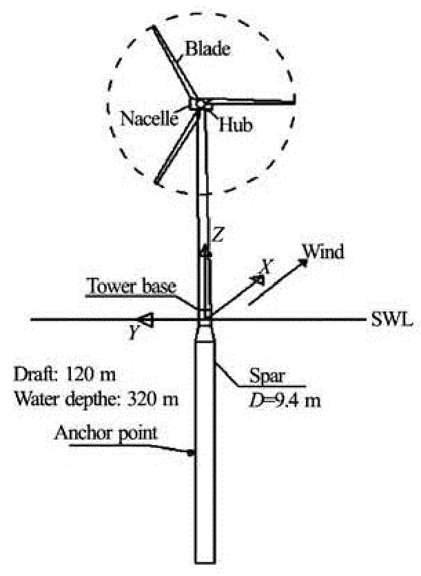
Fig.1 The sketch of the OC3-Hywind
Overall, the OC3-Hywind turbine is a conventional three-bladed, upwind, variable-speed and variable blade-pitch-to-feather controlled 5MW turbine. The integrated properties of the system are listed in Table 1.

Table 1 Gross properties of the OC3-hywind wind turbine system
Specifically, the system is composed of the following parts: (1) platform, (2) tower, (3) nacelle, hub and drivetrain, (4) blade, (5) mooring system.
The detailed properties of every part are described in Ref.[1,14], which is publically available and will not be repeated here.
2. Numerical simulation
The offshore floating wind turbine system is subjected to actions of nonlinear stochastic wave and wind loads, which both have energies in a wide frequency range. In the meanwhile, the control strategies and the coupling of the aerodynamic and hydrodynamic behaviors should be taken into consideration. Therefore, it is a highly non-linear system and it necessary that the integrated time domain analysis be used to obtain the dynamic responses of the system.
The numerical simulation is carried out using the code FAST, which is a state-of-the-art tool for the floating wind turbine simulations.
2.1General motion equations
The equations of motions can be written in the form of Newton’s second law as[2]

where Mijis the (i, j) component of the inertia mass matrix, which depends the nonlinearly on the set of system DOFs (q), the control inputs (u), and the time (t),is the second time derivative of DOF j, and fjis the component of the forcing function associated with DOF j, which depends the nonlinearly on q, u, t and the first time derivatives of DOFs ().
When a hydrodynamic loading is applied on the support platform, the mass matrix would include the added mass components.
2.2Hydrodynamics modeling
Four parts of the hydrodynamic loads are accounted in this model[2]: the linear hydrostatic restoring forces, the added-mass and the damping contributions from the linear wave radiation, including the free-surface memory effects, the incident-wave excitation from the linear diffraction in regular or irregular seas, and the nonlinear viscous drag from incident-wave kinematics and the platform motion. The hydrodynamics model used here does not consider the second-order wave forces, as a reasonable assumption for the spartype floater.
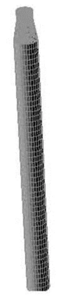
Fig.2 Panel mesh model of the OC3-Hywind spar used within WAMIT
The first three parts can be calculated based on the conventional potential theory. In this paper, the hydrodynamic coefficients for the platform are obtained using the code WAMIT. Figure 2 shows the panel mesh model of the OC3-Hywind spar below the SWL. By applying the Inverse FFT, the frequency-dependent hydrodynamic loading could be transferred into that in the time domain to complete the simulation. The last part of the nonlinear viscous drag could be calculated through the Morison’s Equation.
Furthermore, according to Statoil, the hydrodynamic damping of the motions of the real Hywind platforms is not captured by summing the linear radiation damping (from the potential-flow theory) and the nonlinear viscous drag (from the relative form of the Morison’s formulation). Therefore, the model should be augmented with an additional linear damping matrix by matching modeled still-water free-decay responses[3].
2.3Aerodynamics modeling
The aerodynamic loads are modeled with the blade element momentum (BEM) theory, which assumes that the blades can be divided into small elements that act independently of surrounding elements and operate aerodynamically as two-dimensional airfoils whose aerodynamic forces can be calculated based on the local flow conditions[15]. These elemental forces are summed up along the span of the blade to calculate the total forces and moments exerted on the turbine.

Fig.3 Forces on a blade element
Figure 3 shows a transversal section of the blade element viewed from beyond the tip of the blade, as well as the aerodynamic forces acting on the blade element. The lift and drag coefficients are defined as

where Vrelstands for the relative speed, fLand fDare the lift force and the drag force, respectively, c is the chord of the airfoil, ρ is the air density and α is the angle of attack.
Based on the BEM theory, the relative speed Vrelis[16]
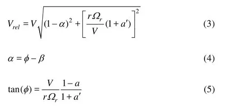
where a and a' are the axial and rotational induction factors, respectively, V is the upstream wind velocity, r is the distance of the airfoil section from the blade root, φ is the angle between the plane of rotation and the relative velocity, β is the local pitch andrΩ is the rotational velocity.
Also, the aerodynamic effects of the tip losses, the hub losses and the skewed wake are incorporated and the dynamic stall model is implemented based on the semi-empirical Beddoes-Leishman model[15].
2.4 Mooring system modeling
The mooring loads are calculated using a quasistatic method and include the apparent weight in fluid, the elastic stretching and the seabed friction of each line. The individual line bending stiffness as well as the inertia and the damping of the mooring system are neglected, but the nonlinear geometric restoration of the whole mooring system is considered[2].
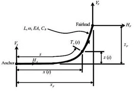
Fig.4 Mooring line in a local coordinate system
Figure 4 shows a local coordinate system for a typical mooring line section. When the support platform displacement is given, each fairlead position is transformed from the global frame to this local system to determine its location relative to the anchor, XFand ZF.
In the local coordinate system, the analytical formulation is given in terms of two nonlinear equations in two unknowns, HFand VF, which stands for the horizontal and vertical components of the effective tension in the mooring line at the fairlead, respectively:

Equations (6) and (7) are solved by the Newton-Raphson iteration scheme.
3. Simulation results and analyses
3.1Effective RAOs of motions and mooring loads
For a linear system, when a periodical excitation of a certain frequency is given, for instance, under a regular wave condition, the response would also be periodical with the same frequency. Normally, this is how the response amplitude operators (RAOs) are defined and calculated, which generally represent the system’s natural attributes versus the wave frequencies. However, for the offshore floating wind turbine system, there are multiple excitation frequencies under a regular wave condition, which is mainly due to the nonlinearity of the system affected by the gyroscopic effect of the rotor and the blade-pitch-controller-induced instability. Such instability is mainly caused by a“negative” damping force (i.e., a decreasing thrust force with an increasing relative wind speed) induced by pitching the blades in wind speeds larger than the rated one. It can be prevented by letting in the design the natural frequency of the blade pitch controller be lower than the natural frequency of the spar pitch motion[3]. As a consequence, the quasi-steady response of the system would not be purely periodic at the wave frequency but oscillate with a superposition of responses at the multiple dominant frequencies. Figure 5 shows a time series of the pitch motion under a regular wave condition (T=10s, H=6 m) and the wind velocity being the rated 11.4 m/s. Figure 6 shows the corresponding power spectrum of the pitch motion. It can be shown from these two figures that the system responds to a single-frequency regular wave with multiple frequency components under a typical operating condition.
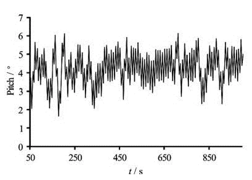
Fig.5 Time series of pitch motion
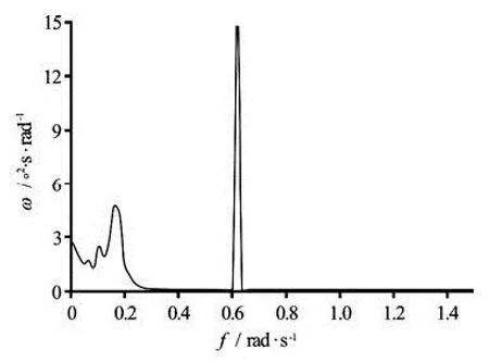
Fig.6 Power spectrum of pitch motion
Therefore, to better estimate the system’s frequency response to waves, a concept of “effective RAOs”was proposed by Jonkman et al.[3]. It is defined as the difference in response amplitudes between the nonlinear time-domain simulations with and without the wave excitation. That is, the outputs are the effective amplitudes of the platform motion and the loads normalized by the wave amplitude versus the wave frequency. Take the surge motion as an example

The calculation is made with a series of regular waves ranging from 0.05 rad/s to 3.5 rad/s, which is set as0.05 rad/s, 0.1 rad/s, 0.2 rad/s, 0.3 rad/s…3.5 rad /s. Besides, since the natural periods of heave and pitch motions are both around 30 s (corresponding circular frequencies lay between 0.2 rad/s-0.3 rad/s), the additional wave frequencies are set in this range, including 0.21 rad/s, 0.22 rad/s…0.29 rad/s to ensure the resonant responses. The same additional wave frequencies are set in the range around the natural surge frequencies as 0.01 rad/s, 0.02 rad/s…0.05 rad/s,
0.06 rad/s…0.09 rad/s. The wind turbine system is under the operating condition with the rotor rotating and the control system in the active state. The wind velocity is chosen to be constant as 8 m/s below the rated velocity, to eliminate the instability induced by the control system. In addition, a case is especially considered under the wind excitation condition without waves. According to the definition mentioned above, the difference of amplitudes between the windwave-induced quasi-steady response and the wind-induced quasi-steady response is the “effective RAOs”of the system to represent its frequency responses to waves.
The wind and the wave both point along x direction. The calculation is carried out in the time domain and the corresponding response amplitudes are derived from steady-state results. The duration of the simulation is sufficiently long to guarantee that the system reaches the steady state as well as complete cycles are included for all motion modes.

Fig.7 Effective RAOs of surge motion
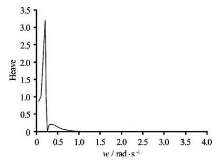
Fig.8 Effective RAO of heave motion
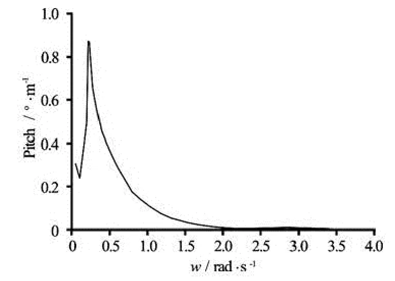
Fig.9 Effective RAO of pitch motion
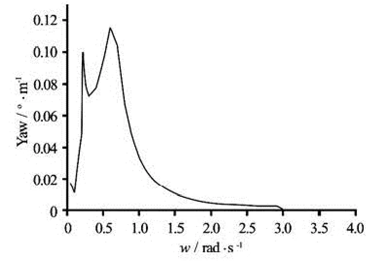
Fig.10 Effective RAO of yaw motion
Figures 7-10 show the effective RAOs of the surge, the heave, the pitch and the yaw motions of the system. Since the wind and the wave are in the same direction, the motion mode in y direction as the sway and the roll are not analyzed here (Sea state: constant wind velocity V =8 m/s , regular waves with a frequency range of ω= 0.05 rad/s, 0.1 rad/s, 0.2 rad/s…3.5 rad/s and additional frequencies around natural periods of motion modes).
From the figures shown above about the “effective RAOs” and the specific data obtained from the calculation, the resonance periods of these motion modes can be acquired (see Table 2).

Table 2 Natural periods of the motion modes
It can be seen that the surge motion response mainly concentrates in the low frequency zone, which coincides with its natural frequency. Meanwhile, the surge motion shows an excitation at 0.25 rad/s, which is close to the pitch natural frequency, and the pitchmotion shows an excitation at the low-frequency zone as well. Therefore, this suggests strongly the coupling between the surge and the pitch. As a fact, due to the center of gravity of the whole system is far below the mean water level, the surge motion defined in the global coordinate system at the mean water level will have a contribution from the pure translational motion and the rotational motion at the center of gravity. This is one cause of the coupling of motions. For the platform yaw, the “effective RAO” shows excitations caused by the gyroscopic loading from the rotating rotor combined with the pitch motion.
Furthermore, from Fig.8, it can be seen that the amplitude of the heave resonance response is about 3.5 m per wave height, which is higher than the usual response amplitude of SPAR studied in the traditional offshore engineering. The cause for this large heave response amplitude is that the OC3-Hywind model used in the initial research is merely a basic and simple concept without a heave plate or other infrastructures to add damping and restrain the heave motion. Nevertheless, the heave motion amplitude is not as critical and rigorously restrained for wind turbines for the risers are not equipped on offshore floating wind turbines.
Comparatively, the pitch response amplitude (see Fig.9) is about 0.9oper wave height, which is a relatively slight response under the wave excitation. This might be related with the aerodynamic damping derived from the wind turbine system. Figure 11 illustrates the layout of the mooring lines and their relative positions to the directions of the wind and the wave.
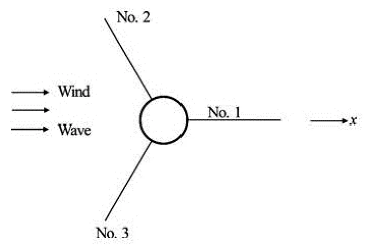
Fig.11 Layout of the mooring lines
As can be seen from Fig.11, the mooring line No. 1 locates in the wind and wave directions. Therefore, the effective RAO of the fairlead tension of the mooring line No.1 is analyzed here and compared with that of the surge motion (see Fig.12). The coincidence of the behaviors of these two cases indicates that the fairlead tension is mostly influenced by the surge motion assuming that the wind and the wave point along the x direction.
3.2Wind-wave induced responses of motions
Under the operation conditions, the system’s movement is mainly due to the wind-wave induced loads. To further estimate the characteristics of the system, numerical simulations under wind-wave conditions are conducted to obtain the global responses and the mooring loads. Two cases are compared to see the effects induced by the wave loads only and the windwave loads.
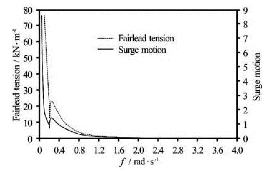
Fig.12 Comparison of the effective RAOs of fairlead tension and the surge motion (Sea state: constant wind velocity V =8 m/s , regular waves with a frequency range of ω= 0.05 rad/s, 0.1 rad/s, 0.2 rad/s…3.5 rad/s)
Here the rated wind velocity V=11.4 m/s . When at the rated operation point, the wind thrust force reaches the maximum so that the wind-induced loads become most significant under this situation. To simplify the simulation conditions and focus on major issues in the present study, the wind velocity is set to be constant in the simulation. The irregular waves with the significant wave height 6 m and the peak period 10 s are assumed in the JONSWAP spectrum. Also, the wind and the wave are assumed to point along the same x direction.
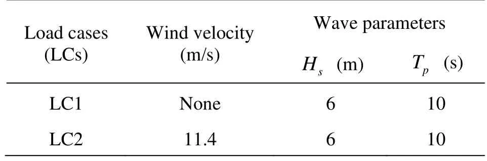
Table 3 Load cases and corresponding sea states
The load cases (LCs) and the corresponding sea states are summarized in Table 3. In both load cases, the same time series of the wave input are adopted to make sure that the results are comparable.
The spectrum analyses are made based on the 2.5 h time domain simulations in the FAST code. Typical and dominant motion modes of the system are analyzed as the surge, the heave and the pitch. Figure 13 shows the wave power spectrum generated by the FAST and used in the simulation.
The platform surge power spectra for the wave only and the wind-wave induced cases are shown in Fig.14. It can be seen that for the surge motion, thewave-induced response mainly concentrates in wave frequencies. Nevertheless, compared with the windwave induced response, the amplitude of the wave-induced response is significantly smaller, which is an obvious fact that the surge motion is mainly dominated by the wind loads and the response concentrates on the low frequency zone of the surge resonance frequency. Furthermore, it can be seen that the wind-induced loads have little influence on the response of wave frequencies, which indicates that the wind and wave induced loads affect the turbine’s surge response separately in a decoupled way. And besides the surge resonance response frequency, the wind-induced loads also stimulate a response around 0.2 rad/s, which is the pitch resonance frequency. This also indicates the coupling effect between the surge and pitch motions.
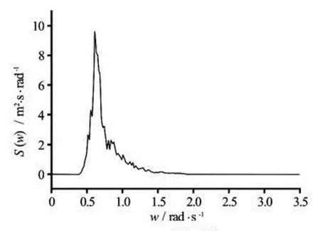
Fig.13 Wave power spectrum generated in the simulation
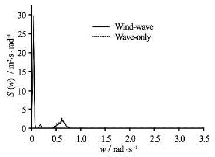
Fig.14 Platform surge motion spectra under a wave conditionand a wind-wave condition with H s=6 m and Tp= 10 s based on a 2.5 h time domain simulation in FAST
Figures 15 and 16 show the comparative results of the responses of the heave and pitch motions under the two cases (Under a wave condition and a windwave condition with Hs=6 m , Tp=10s and V= 11.4 m/s based on a 2.5 h time domain simulation in FAST). These two motion modes share similar trends and are discussed together. From the results in these two figures, it can be seen that the wind-induced loads does not affect the wave frequency response for the heave and pitch motions significantly, which shows the same tendency as that of the surge motion. There is a slightly reduction of the amplitude for the wave frequency response under the wind-wave condition, which might be induced by the effect of the aerodynamic damping. For the pitch motion shown in Fig.16, it is clearly seen that, under the wind-wave condition, two resonance responses appear around the surge natural frequency (about 0.05 rad/s) and the pitch natural frequency (about 0.2 rad/s), separately, which once again indicates the coupling effect of the surge and pitch motions. Meanwhile, the similar trends of the heave motion (Fig.15) indicates that the coupling of the surge and the pitch also affects the heave motion in the low-frequency response, which is rare in the traditional offshore floating platforms. These behaviors of the platform motions are special for the floating wind turbine system which is mainly related to the wind-induced loads and the whole system’s nonlinear characteristics. Further researches should be conducted to discuss the mechanisms behind these characteristics.
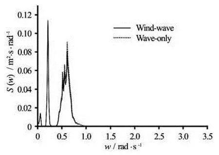
Fig.15 Platform heave motion spectra

Fig.16 Platform pitch motion spectra
3.3Wind-wave induced structural responses
As analyzed in the above section, the platform motions respond to the wind and wave induced loads in separate frequency zones, meanwhile, the coupling effects among several motion modes exist due to the integrated wind-wave induced loads. To further evaluate these effects on the system safety, several criticalloads on the system including the mooring line fairlead tension and the shear forces as well as the bending moments in the interface of the tower and platform are calculated and analyzed. The load cases discussed here are the same as in the above section (Table 3). The statistical analyses are carried out based on the 2.5 h time domain simulations in the FAST code.
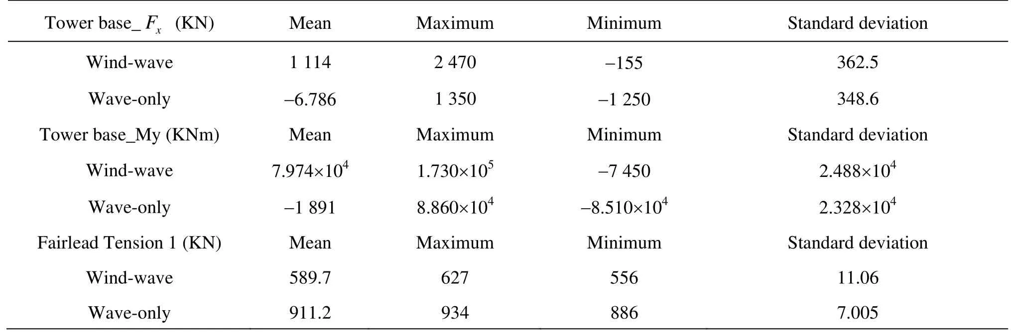
Table 4 Statistical results of system loads
In Table 4, the statistical results of the shear force and the bending moment in the interface between the tower and the platform, which is the tower base, as well as the fairlead tension of the mooring line No.1 are summarized. As the wind and the wave both point along X direction, the analysis of the loads on the tower base mainly focuses on the shear force in X direction and the transmitted bending moment in Y direction (Tower Base_Fxand Tower Base_My).
Since the pretension for the mooring lines is around 911 KN, it can be seen that for all four system loads analyzed here, the mean value of the responses varies mostly between the wind-wave induced response and the wave-only induced one. This suggests that the mean value of the response is mainly due to the wind-induced loads, which is very reasonable when we take the fairlead tension of the mooring line 1 as an example. Due to the wind-induced loads, the system has large drifts as the mean value of the surge motion goes above 20 m (derived from results of the motion responses), in consequence of which, the mean value of the fairlead tension of the mooring line 1 changes from the original pretension to a largely deduced amount. Furthermore, this result indicates a noticeable situation that if on the system acts a large force induced by external environmental conditions in X direction, and there is a corresponding large drift displacement, the mooring line 1 would have the risk of failure for being slack due to the arrangement of the mooring lines and the wind turbine configuration (Fig.11).
Meanwhile, the standard deviation of responses shows a less variation between the two load cases, which indicates that the wave-induced loads are mainly responsible for the fluctuation of the responses.

Fig.17 Time trace for the tower base shear force Fxunder the two load cases
The time history of Tower Base_Fx(Fig.17) clearly shows the tendency. It can be seen that the fluctuation of the Tower Base_Fxin the time trace is almost the same in the two load cases, while when under the wind-wave condition, the mean value of the load varies from zero rapidly to around 1 100 KN at the beginning of the time trace.
The corresponding response of the system loads, as a superposition of the mean value induced mainly by the wind and the fluctuation induced mainly by the wave, could provide a valuable reference for the safety evaluation and the structural design.
4. Conclusions
In this paper the dynamic responses of motions and mooring loads for a spar-type floating wind turbine induced by wind and wave loads are analyzed. Several conclusions could be drawn from the analyses.
(1) The gyroscopic effect of the rotor and the blade-pitch-controller-induced instability bring about a strong nonlinearity for the system, as a consequenceof which, the system responds to multiple excitation frequencies when under a regular wave condition. To better estimate the system’s frequency response to waves, a concept of “effective RAOs” is adopted here and the specific method to obtain “effective RAOs” is introduced.
(2) Results for the “effective RAOs” are obtained in the paper, from which the natural frequencies of the platform’s motion modes are summarized. Meanwhile, the results of “effective RAOs” indicate a coupling between the surge and the pitch of the platform. For the platform yaw motion, on the other hand, it shows excitations caused by the gyroscopic loading from the rotating rotor combined with the pitch motion. Since the wind and the wave are set to point along in x direction, a typical mooring line load shows a coincidence with the surge motion.
(3) Furthermore, the responses of the global motions and the system loads are simulated under two comparative cases with wave loads only and joint wind-wave induced loads to see the effects of the wind and the wave comparatively. From the results in the paper, it can be seen that the wind-induced loads mainly influence the low-frequency excitations including the resonance response in the surge and pitch natural frequencies but have little effect on the wave-frequency responses. Especially for the surge motion, the response amplitude is much larger under the windwave conditions, which indicates that the surge motion is mainly stimulated by the wind loads. Meanwhile, the coupling of the surge and the pitch is also validated under the wind-wave conditions.
(4) The corresponding response of the system loads is a superposition of the mean value induced mainly by the wind and the fluctuation induced mainly by the wave. The result also indicates a noticeable situation that if on the system acts a large force induced by external environmental conditions in X direction and a corresponding large drift displacement occurs, the mooring line 1 would have the risk of failure for being slack.
[1] JONKMAN J., BUTTERFIELD S. and MUSIAL W. et al. Definition of a 5-MW reference wind turbine for offshore system development[R]. Technical Report NREL/ TP-500-38060, Golden, Colorado, USA: NREL, 2009.
[2] JONKMAN J. Dynamics of offshore floating wind turbines–Model development and verification[J]. Wind Energy, 2009, 12(5): 459-492.
[3] JONKMAN J., LARSEN T. J. and HANSEN A. M. et al. Offshore code comparison collaboration within IEA wind Task 23: Phase IV results regarding floating wind turbine modeling[C]. European Wind Energy Conference. Warsaw, Poland, 2010.
[4] MADJID K., MOAN T. Wave-and wind-induced dynamic response of a spar-type offshore wind turbine[J]. Journal of waterway, port, coastal, and ocean engineering, 2011, 138(1): 9-20.
[5] SKAARE B., HANSON T. D. and NIELSEN F. G. et al. Integrated dynamic analysis of floating offshore wind turbines[C]. European Wind Energy Conference and Exhibition. Milan, Italy, 2007.
[6] DOMINIQUE R., CERMELLI C. and AUBAULT A. et al. Wind float: A floating foundation for offshore wind turbines[J]. Journal of Renewable and Sustainable Energy, 2010, 2(3): 033104.
[7] HYUNKYOUNG S., CHO S. and JUNG K. Model test of an inverted conical cylinder floating offshore wind turbine moored by a spring-tensioned-leg[J]. International Journal of Naval Architecture and Ocean Engineering, 2014, 6(1): 1-13.
[8] MARTIN H. R., KIMBALL R. W. and VISELLI A. M. et al. Methodology for wind/wave basin testing of floating offshore wind turbines[J]. Journal of Offshore Mechanics and Arctic Engineering, 2014, 136(2): 020905.
[9] KOO B. J., GOUPEE A. J. and KIMBALL R. W. et al. Model tests for a floating wind turbine on three different floaters[J]. Journal of Offshore Mechanics and Arctic Engineering, 2014, 136(2): 020907.
[10] GOUPEE A. J., KOO B. J. and KIMBALL R. W. et al. Experimental comparison of three floating wind turbine concepts[J]. Journal of Offshore Mechanics and Arctic Engineering, 2014, 136(2): 020906.
[11] ZHANG R. Y., CHEN C. H. and TANG Y. G. et al. Research development and key technical on floating foundation for offshore wind turbines[J]. Advanced Materials Research, 2012, 446: 1014-1019.
[12] ZHAO Y. S., YANG J. M. and HE Y. P. Preliminary design of a multi-column TLP foundation for a 5-MW offshore wind turbine[J]. Energies, 2012, 5(10): 3874-3891.
[13] REN N. X., LI Y. G. and OU J. P. The wind-wave tunnel test of a tension-leg platform type floating offshore wind turbine[J]. Journal of Renewable and Sustainable Energy, 2012, 4(6): 063117.
[14] JONKMAN J. Definition of the floating system for phase IV of OC3[R]. Technical Report, NREL/TP-500-47535, Golden, Colorado, USA: NREL, 2010.
[15] HANSEN M. O. L., SORENSEN J. N. and VOUTSINAS S. et al. State of the art in wind turbine aerodynemics and aeroelasticity[J]. Progress in Aerospace Sciences, 2006, 42(4): 285-330.
[16] HANSEN M. O. L. Aerodynamics of wind turbines[M], 2nd Edition, London, UK: Earthscan, 2008.
10.1016/S1001-6058(14)60095-0
* Project supported by the State Key Laboratory of Ocean Engineering, Shanghai Jiao Tong University (Grant No. GKZD010023).
Biography: MA Yu (1989- ), Female, Ph. D. Candidate
HU Zhi-qiang,
E-mail: zhqhu@sjtu.edu.cn
猜你喜欢
——邢伟中檀香扇作品欣赏
杂志排行

水动力学研究与进展 B辑的其它文章
- Non-spherical multi-oscillations of a bubble in a compressible liquid*
- Theoretical and experimental studies of the transport process of micro-particles in static water*
- Wave-induced flow and its influence on ridge erosion and channel deposition in Lanshayang channel of radial sand ridges*
- Experimental study of flow field in interference area between impeller and guide vane of axial flow pump*
- An analysis of dam-break flow on slope*
- Performance of the bio-inspired leading edge protuberances on a static wing and a pitching wing*