Large-eddy simulation of the flow past both finite and infinite circular cylinders at Re =3900*
2015-04-20ZHANGHui张蕙YANGJianmin杨建民XIAOLongfei肖龙飞Haining吕海宁
ZHANG Hui (张蕙), YANG Jian-min (杨建民), XIAO Long-fei (肖龙飞), LÜ Hai-ning (吕海宁)
State Key Laboratory of Ocean Engineering, Shanghai Jiao Tong University, Shanghai, China,E-mail: zh.hui@sjtu.edu.cn
Introduction
The flow around a circular cylinder is a classic and important topic in marine hydrodynamics. Many offshore structures are of cylindrical shape, such as the risers, the pipelines and the hard tank of Spar platforms. The exposure of the large cylinder, like the hard tank of a Spar platform, to the current will lead to a complex wake mechanism causing vortex-induced motions (VIMs). Because the hard tank is finite in height, the numerical model of the hard tank is modelled as a finite circular cylinder. The flow over a finite cylinder has been studied extensively, both experimentally and numerically, for several decades.
In experiments, one of the most recent experiments was conducted by Park and Lee[1,2]in a closed-return type subsonic wind tunnel, to study the flows around finite cylinders with aspect ratios of 6, 10 and 13 at the Reynolds numberRe=2×10⁴, focusing on the influence of various atmospheric boundary layers on the flow structure. Furthermore, Park and Lee[3]studied the influence of the free end corner shape on the flows around finite-height cylinders. PIV investigations were carried out on the cylinders with aspect ratio of 6 at the Reynolds numberRe=7500.
Unlike experiments, large-eddy simulations (LES)of finite-height cylinders were mainly focused on the short aspect ratio cylinders. Fröhlich and Rodi[4]simulated a flow past a finite cylinder with aspect ratio of 2.5 at the Reynolds numberRe=4.3×10⁴using LES with the finite volume method (FVM). They successfully predicted the main features of the flow, but not the details of the flow on the cylinder’s free end and near the ground due to a low resolution. Lee et al.[5]later simulated the same flow as in Fröhlich and Rodi[4]but with the finite element method (FEM). The results with FVM and FEM are similar. Recently, the numerical results with the LES for finite circular cylinders at different aspect ratios and Reynolds numbers are compared with the corresponding experimental data. It is found that they are in good agreement in terms of the velocities, the pressures on the surface of cylinders, the turbulence stresses and the streamlines projected on several planes, as reported by Pattenden et al.[6], Palau-Salvador et al.[7]and Krajnović[8].
The benchmark case of the flow around a circular cylinder at a subcritical Reynolds numberRe=3900 has been discussed during the past two decades, both through experiments and numerical simulations. A detailed review of experiments was made by Norberg[9].Recent numerical researches at this low subcritical Reynolds number were mainly based on the LES. A series of LES computations of the flow past a circular cylinder at the Reynolds numberRe=3900 were carried out by Kravchenko and Moin[10], Tremblay et al.[11], Wissink and Rodi[12], and Parnaudeau et al.[13].These studies focused on the influence of the subgrid scale models, the grid resolution and the discretization schemes on the quality of the LES and the comparisons with experimental results.
The objectives of the present work are to use the LES to explore the time-averaged flows around circular cylinders. The flows past both finite and infinite circular cylinders of the same diameter are investigated at the subcritical Reynolds numberRe=3900. As the flow around the free end is not fully understood,the present work is to explore the differences of flow mechanisms between the finite and infinite circular cylinders. It is shown that the free end of the finite circular cylinders affects the wake region significantly.The mean drag coefficient and the fluctuating lift coefficient of the finite circular cylinder are smaller than those of the infinite circular cylinder. The three-dimensional separation and the separated shear layer instability of the finite circular cylinder are clearly observed. The existence of an arch vortex in the average flow downstream of the free end is demonstrated.
1. Numerical model and method
1.1 Governing equations and subgrid-scale modelling
The large-eddy simulations are implemented in this study for the turbulence closure. In the LES model, the large-scale motions are explicitly computed, and the eddies with scales smaller than the grid or filter size are modelled to represent the effects of unresolved motions on the resolved scales.
The governing LES equations are the incompressible Navier-Stokes equations. The momentum and continuity equations filtered with the implicit spatial filter can be written as:
wherei,j∈ [1,2,3],is the resolved velocity component inx,yandzdirections respectively,tis the time,xiis the respective direction in the Cartesian coordinate system,ρis the density of the fluid, is the resolved pressure andijτrepresents the non-resolvable subgrid stress,νis the kinematic viscosity of the fluid.
These equations are derived by applying a filtering operation to the Navier-Stokes equations. The filtered variable in the governing Eqs.(1) and (2) are obtained implicitly through the spatial discretization.The filtering operation with a filtering kernelGis given as
Due to the small scales of the turbulence , the influence on the large energy carrying scales in Eq.(1)appears in the subgrid scale (SGS) stress tensor,=, which must be modelled.
The commonly used SGS model proposed by Smagorinsky is used in this study for its simplicity and low computational cost. The Smagorinsky model is based on the Boussinesq approximation, which assumes that the turbulence stresses behave in the same manner as the large scale strain rate tensorSij

whereijδdenotes the Kronecker delta andνsgsis the SGS eddy viscosity. The strain rate tensor in the resolved field can be written as
where

The SGS eddy viscosity, is a function of the strain rate tensor and the subgrid lengthl:

whereCsis a constant and Δ the filter-width. Thevalue of the model constantCsis flow-dependent and found to vary from 0.065 to 0.25. Here, the constant is set to beCs=0.2. The filter width Δ is correlated to the typical grid spacing through the cube root of the cell volume. In this study, the van Driest damping function[14]is adopted., where Δmeshis the cubic root of the mesh cell volume,k=0.41 the von Karman constant,=0.518,A+=26,nthe wall normal distance, and+nthe nondimensionalized wall normal distance, taken as, whereis the wall friction velocity.
1.2 Numerical method
Equations (1) and (2) are discretized using a finite volume method (FVM) for solving the incompressible Navier-Stokes equations. All simulations are performed using the open source code OpenFOAM, a computational fluid dynamics (CFD) solver with extensive libraries for turbulence modelling. It is based on the tensorial approach and object-oriented techniques. The Pressure Implicit with Splitting of Operators (PISO) algorithm is used for the pressure-velocity coupling. The spatial schemes for the interpolation,the gradient, the Laplacian and the divergence terms are linear, Gauss linear, Gauss linear corrected and Gauss linear, respectively. All these schemes are of second-order accuracy. The time integration is performed using the second-order Crank-Nicolson scheme.Further details of these schemes are given in Guide.

Fig.1 Computational domain (not to the real scale) and boundary conditions

Fig.2 Computational mesh
2. Computational overview and validation
2.1 Computational overview
Based on the hard tank of a Truss Spar model,the numerical model is 0.65 m in diameter and 1.5 in the height-to-diameter ratioH/D.A computational domain of(length×width×height) is used in the simulations, as shown in Figs.1(a) and 1(c).
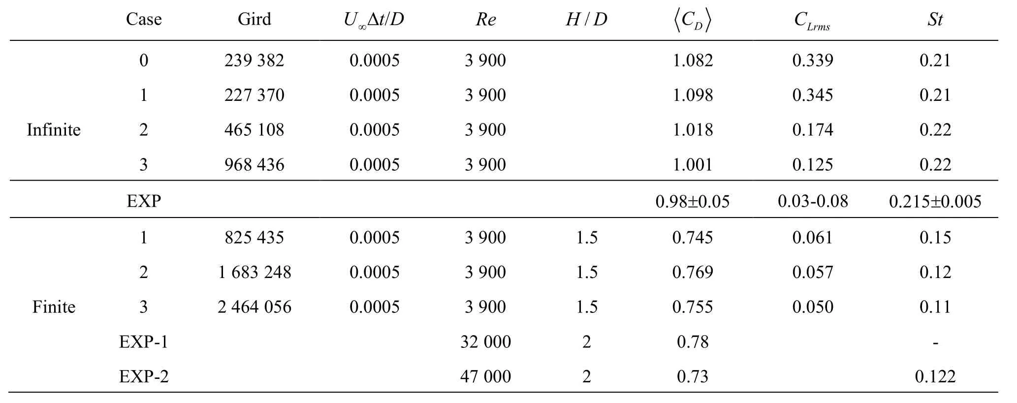
Table 1 Comparison of the numerical results with experimental data for both circular cylinders and the validation of the numerical results with different grid resolutions, i.e., Cases 1-3. Here, “EXP” represents the experimental data from Cardell[15], Norberg[9], “EXP-1” from Kawamura et al.[16] and “EXP-2” from Okamoto and Sunabashiri[17]
The inlet and the outlet in the numerical simulation are placed 6.5Dand 20.5Dfrom the cylinder, respectively. The blockage ratio is 7%. The Cartesian coordinate system (x,y,z) is used in this study and the origin of the coordinates is at the centre of the finite cylinder. Here,x,yandzrepresent the streamwise, transverse and spanwise directions, respectively. For comparison, the flow past an infinite circular cylinder in the same diameter as the finite cylinder is also simulated. The computational domain is(length×width×height), with the same top view as the finite cylinder but a different side view,as shown in Figs.1(a) and 1(b). For simplicity, the free end of the finite circular cylinder is called the “top”,and the other end is called the “bottom” and the region behind the cylinder is called the “wake” region.
The computational domain is divided into 62 blocks to control the grid distributions. An O-type grid of 0.1Din width is created around the cylinder in order to provide an easy control of the cell size in the immediate vicinity of the cylinder. The maximum dimensionless first layer heightn+of the finite and infinite circular cylinders is 0.97 and 0.56, respectively. In the spanwise direction, fine grids are concentrated on the free end of the finite cylinder, while the grids are uniformly distributed for the infinite cylinder. Figure 2 shows the grids used in the numerical simulation.
The no-slip boundary condition is specified on the surfaces of both cylinders, and the pressure is set with zero normal gradient. At the inlet boundary, a uniform velocity and zero normal gradient pressure are prescribed. At the outlet boundary, the pressure is set as zero and the velocity is set with zero normal gradient. At the top and bottom boundaries, the symmetry boundary conditions are specified. At the side boundaries, the free-slip and zero normal gradient for the pressure are specified.
To better present the post-process results, a symbolis used in this paper. For the finite circular cylinder,means the time-averaged value with careful elimination of the transient part of their timedependent variations. While for the infinite circular cylinder,means the average in time and in the spanwise direction.
2.2 Validation
To examine the performance of the numerical simulation for both finite and infinite circular cylinders,a comparison with the available experimental data in references is made. The numerical results at three different grid resolutions for both cylinders and the available experimental data are listed in Table 1.
The time-averaged drag coefficientCD, the lift fluctuationCLrms, and the Strouhal numberStare also listed in Table 1. Case 0 of the infinite circular cylinder is taken to validate the computational domain.The computational domain of Case 0 is 35D×20D×H(length×width×height). The length from the inlet to the centre of the cylinder is 15D. The absolute differences of the computed quantities between Case 0and Case 1 are less than 2%, which show that the results are converged. Therefore, the initial computational domain is selected as the computational domain.

Fig.3 Validation of the results with different grid resolutions(i.e., Cases 1-3) given in Table 1: The distribution of the time-averaged streamwise velocity and pressure coefficient
It is found that the results for Cases 2 and 3 agree better with the experimental data[9,16]for the infinite circular cylinder. Even though the experimental data of a finite cylinder at the same Reynolds number and the sameratio are not available, the related experimental data[17,18]at similar Reynolds numbers andratios are also listed in Table 1 for reference.Table 1 indicates that the results for finite cylinder Cases 2 and 3 overlap together.
Figure 3 shows the distribution of the time-averaged streamwise velocityand the pressure coefficientof both circular cylinders. The definition of the pressure coefficient is
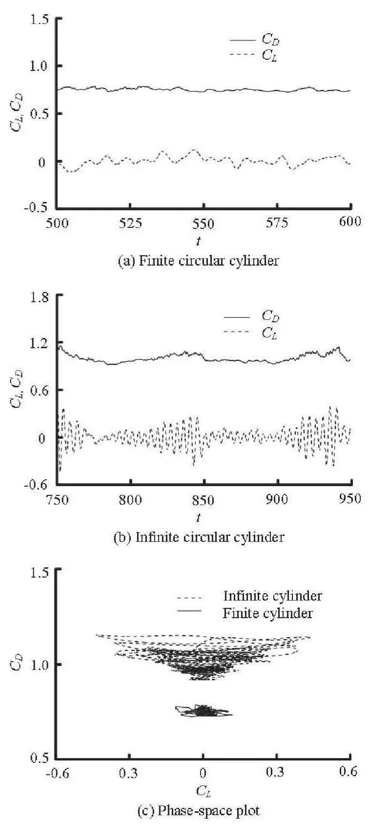
Fig.4 Time-dependent lift and drag coefficients
The recirculation region increases from Case 1 to Case 3. This leads to a decrease of the drag. Thepressure coefficient is higher in the shorter recirculation region. Case 1 has the shortest recirculation length and the highest back-pressure and drag coefficient. The results for Cases 2 and 3 overlap together, indicating a reasonable convergence for the grid resolution at this time step. Hereinafter, the results of both finite and infinite circular cylinders shown in the later part of the paper are those in Case 3.The grid number is 2.46×10⁶and 0.97×10⁶for the finite and infinite circular cylinders, respectively, and the time step is 0.0005D/U∞.
3. Results and discussions
3.1 Average quantities
The lift and drag coefficients are considered as important parameters in the investigation of the flow phenomenon. Figures 4(a) and 4(b) show the time-dependent lift and drag coefficientsCLandCDof the finite and infinite circular cylinders, respectively. An obvious reduction of the time-averaged drag and the fluctuating lift of the finite circular cylinder is observed as compared to those of the infinite circular cylinder. This reduction is due to the intrusion of the flow over the top into the wake[17]. In Fig.4(c), the phasespace plots of the force coefficientsare shown to compare the time-dependent forces on the cylinders. It is found that the force coefficients of the finite circular cylinder are limited to only a local region, indicating that the force fluctuation is significantly suppressed.

Fig.5 Profiles of power spectral density of time-dependent lift coefficient for the finite and infinite circular cylinders
The time-averaged drag coefficientand the lift fluctuationare estimated and listed in Table 1. From the comparison of the values of, it is observed that theof the finite circular cylinder is smaller than that of the infinite circular cylinder with a reduction up to 25%. Meanwhile, compared with the values of, the fluctuating lift of the finite circular cylinder is significantly suppressed with a reduction up to 60%.
The lift fluctuation of a cylinder is closely related to the vortex shedding in the wake. The frequency of the vortex shedding and the Strouhal number are the main parameters in the analyses of the features of the vortex shedding. The Strouhal number is defined as,wherefis the vortex shedding frequency. Figure 5 shows the power spectral densities of the time-dependent lift coefficient of the finite and infinite circular cylinders. The vortex shedding frequency is defined as the frequency of the spectral peak.As shown in Fig.5, the frequency corresponding to the spectral peak of the infinite circular cylinder is approximately 0.22. This is consistent with the experimental data in the range of 0.21-0.22. Compared with the results of the infinite circular cylinder, the spectral peaks for the finite circular cylinder are relatively small, indicating an almost complete suppression of the flow unsteadiness.

Fig.6 Distributions of the mean streamwise velocity and pressure coefficient
To analyze the impact of the different computational models, other averaged quantities of the flow region are calculated for comparisons. Figure 6 shows the distributions of the mean streamwise velocity and the pressure coefficient for both finite and infinite circular cylinders in the spanwise direction. In Fig.6(a),it is observed that the mean streamwise velocity of the finite circular cylinder varies with the horizontal planeszis const. Close to the top plane of, the recirculation region is gradually weakened and eventually disappears. The recirculation region of the in-finite circular cylinder keeps almost the same as that at the middle plane of the finite circular cylinder,while the mean streamwise velocity gets smaller afterCompared to the finite circular cylinder, the pressure coefficient of the infinite circular cylinder in Fig.6(b) is smaller in the wake region. The flow over the top into the wake significantly influences the wake region characteristics of the finite circular cylinder.

Fig.7 Vortical structures revealed by iso-surface of the Q-criterion (Q=1), for infinite circular cylinder (left) and finite circular cylinder (right)
3.2 Flow visualization
The vortex structural classification of the unsteady flow pattern is a very difficult issue, due to the tremendous number of small structures resulting from the complex flow phenomena. Figure 7 shows the instantaneous vortex structures of the flow field depicted by iso-surfaces of theQ-criterion.
whereSandΩdenote the strain and the rotation tensors, respectively. A positiveQindicates the regions in which the rotation exceeds the strain. It must be recalled that theQ-criterion can only be applied to the resolved scales obtained by the LES and that the vortical structures may be different if the whole flow field is considered[18,19].
The instantaneous visualizations of the flow field are made to detect the main flow features. The interaction between the flow separation from the sidewalls and the top of the finite circular cylinder leads to complicated vortex dynamics. Due to the effect of the free end, the development of straight, two-dimensional Von Karman vortices are bent and distorted as they travel along the wake. Compared with the infinite circular cylinder, highly distorted Von Karman vortices are visible in the near wake of the finite circular cylinder as shown in Fig.7. For the finite circular cylinder with the height-to-diameter ratio of 1.5, alternating vortex shedding persists up to the free end. Some researchers[4]indicate that with the height-to-diameter ratio over this value, perturbations are only in small scales and restricted to the close vicinity of the cylinder due to the strong downward motion behind the cylinder. Figure 7 also shows that the shedding vortices of the finite circular cylinder increase in size and become smoother further downstream in the wake.The vortical structures near the base region of the finite circular cylinder are significantly less vigorous than those of the infinite circular cylinder.
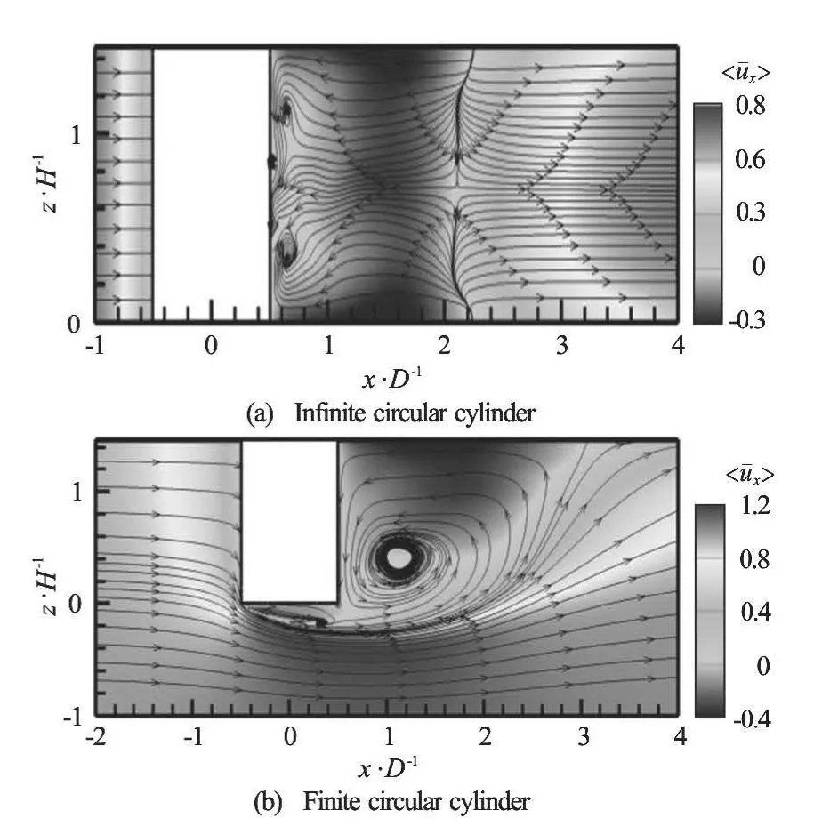
Fig.8 Time-averaged streamlines and contours of mean streamwise velocity in the centre-plane y/D=0
3.3 Time-averaged flow
The time-averaged flow is discussed in this subsection. Figure 8 shows the time-averaged streamlines and contours of the mean streamwise velocity in the centre-planey/D=0 of the infinite and finite circular cylinders.
The recirculation region is regular for the infinite circular cylinder aroundas shown in Fig.8(a). On the other hand, behind the finite circular cylinder, from the streamlines in the centre-plane, one sees a large recirculation region, with the centre of the vortex located atIn combination with the time-averaged streamlines in the crosssection planes, Fig.8(b) shows that there is an arch vortex of “U” shape standing behind the finite circularcylinder. This arch vortex is generated closely behind the free end with a horizontal axis.
Figure 9 shows the time-averaged streamlines and contours of the mean velocity components in three cross-section planes of the finite circular cylinder and in thezaxis-averaged plane of the infinite circular cylinder. It is observed that the near wake vortical structures behind the finite circular cylinder are modified significantly as compared with the flow past the infinite circular cylinder. As shown in Fig.9(a), because no obvious vortex shedding takes place near the top of the finite cylinder, the recirculation is much shorter and all fluctuations are smaller. In Fig.9(c), a tendency of the fluctuations spreading away from the centre-plane is observed forx/D>3.
As shown in Fig.8, an arch vortex behind the finite circular cylinder is observed. In Fig.9, from the horizontal cuts atit is seen that their axis becomes oblique from the bottom to the top. The vertical axis of this arch vortex is aroundx/D=1.9 atz/H=0.5, while that aroundx/D=1.5 is atz/H=1. The arch vortex is a feature of the average flow, but not the instantaneous one and can be observed in the flow around a surface-mounted cube simulated with the LES.

Fig.10 The iso-contours of mean vorticity magnitude. There are 20 contour levels between 0 and 10
Figure 10 shows the iso-contours of the mean vorticity magnitude in three cross-section planes of the finite circular cylinder and thezaxis-averaged plane of the infinite circular cylinder. In Fig.10(d), the separated free-shear layers with longitudinal scale of about one cylinder diameter is observed for thezaxis-averaged plane of the infinite circular cylinder.Relatively longer free-shear layers are shown in the finite circular cylinder case. It can be observed that the separated free-shear layers of the finite circular cylinder are relatively more stable and they roll up into vortices in the further downstream positions. This leads to a reduction of the suction near the base region of the finite circular cylinder, which is reasonably related to the higher-base-pressure distribution in Fig.6(b). The feature of the von Karman vortices ismuch more obvious in the near wake of the infinite circular cylinder, while the shed vortices are highly distorted in the wake region of the finite circular cylinder.
4. Conclusions
Numerical investigations of the flow past a finite circular cylinder are carried out by the LES technique at a Reynolds numberRe=3900. For comparison,the flow past an infinite circular cylinder of the same diameter is also simulated to reveal their differences.Complex flow phenomena, including the drag reduction and the fluctuating lift suppression, the vortical structures in the wake region and the shear layer instability, are studied systematically.
The forces on the finite circular cylinder are significantly suppressed compared to those on the infinite circular cylinder. Due to the higher base pressure, the time-averaged drag coefficient of the finite circular cylinder is smaller than that of the infinite circular cylinder with a drag reduction up to 25%. The fluctuating lift coefficient of the finite circular cylinder is nearly zero with a great reduction of 60% as compared to that of the infinite one.
The vortical structures near the base region of the finite circular cylinder are significantly less vigorous than those of the infinite circular cylinder. The interaction between the flow separation from the sidewalls and the top of the finite circular cylinder leads to complicated vortex dynamics. With the effect of the free end, the development of straight, two-dimensional Von Karman vortices are bent and distorted as they travel along the wake. An arch-type vortex with the axis near the top is observed in the wake region of the finite circular cylinder.
The free-shear layers shed from the finite circular cylinder are more stable than that from the infinite circular cylinder. The shear layers roll up from the finite circular cylinder is delayed to a further downstream position, leading to a reduction of the suction near the base of the cylinder or a higher-base-pressure distribution.
Further investigations might be focused on the flow phenomena of the finite circular cylinder.
[1] PARK C. W., LEE S. J. Free end effects on the near wake flow structure behind a finite circular cylinder[J].Journal of Wind Engineering and Industrial Aerodynamics, 2000, 88(2-3): 231-246.
[2] PARK C. W., LEE S. J. Flow structure around a finite circular cylinder embedded in various atmospheric boundary layers[J]. Fluid Dynamics Research, 2002,30(4): 197-215.
[3] PARK C. W., LEE S. J. Effects of free-end corner shape on flow structure around a finite cylinder[J]. Journal of Fluids and Structures, 2004, 19(2): 141-158.
[4] FRÖHLICH J., RODI W. LES of the flow around a circluar cylinder of finite height[J]. International Jour- nal of Heat and Fluid Flow, 2004, 25(3): 537-548.
[5] LEE T., LIN C. L., and FRIEHE C. A. Large-eddy simulation of air flow around a wall-mounted circular cylinder and a tripod tower[J]. Journal of Turbulence, 2007, 8(29): 1-28.
[6] PATTENDEN R. J., BRESSLOFF N. W. and TURNOCK S. R. et al. Unsteady simulations of the flow around a short surface-mounted cylinder[J]. International Journal for Numerical Methods in Fluids, 2007, 53(6): 895-914.
[7] PALAU-SALVADOR G., STOESSER T. and FRÖHLICH J. et al. Large eddy simulations and experiments of flow around finite-height cylinders[J]. Flow, Turbu- lence and Combustion, 2010, 84(2): 239-275.
[8] KRAJNOVIĆ S. Flow around a tall finite cylinder explored by large eddy simulation[J]. Journal of Fluid Mechanics, 2011, 676: 294-317.
[9] NORBERG C. Fluctuating lift on a circular cylinder:Review and new measurements[J]. Journal of Fluids and Structures, 2003, 17(1): 57-96.
[10] KRAVCHENKO A. G., MOIN P. Numerical studies of flow over a circular cylinder atReD=3900[J]. Phy- sics of Fluids, 2000, 12(2): 403-417.
[11] TREMBLAY F., MANHART M. and FRIEDRICH R.LES of flow around a circular cylinder at a subcritical Reynolds number with Cartesian grids[M].Dordrecht, The Netherlands: Kluwer Academic Publi- shers, 2004, 133-150.
[12] WISSINK J. G., RODI W. Numerical study of the near wake of a circular cylinder[J]. International Journal of Heat and Fluid Flow, 2008, 29(4): 1060-1070.
[13] PARNAUDEAU P., CARLIER J. and HEITZ D. et al.Experimental and numerical studies of the flow over a circular cylinder at Reynolds number 3 900[J]. Physics of Fluids, 2008, 20(8): 085101.
[14] Van DRIEST E. On turbulent flow near a wall[J]. AIAA Journal, 2003, 41(7): 259-264.
[15] CARDELL G. S. Flow past a circular cylinder with a permeable wake splitter plate[D]. Doctoral Thesis,Pasadena, CA, USA: California Institute of Technology, 1993.
[16] KAWAMURA T., HIBINO T. and MABUCHI I. et al.Flow around a finite circular cylinder on a flat plate (cylinder height greater than turbulent boundary layer thickness)[J]. Bulletin of the JSME, 1984, 27(232): 2142- 2151.
[17] OKAMOTO S., SUNABASHIRI Y. Vortex shedding from a circular cylinder of finite length placed on a ground plane[J]. Journal of Fluids Engineering, 1992, 114(4): 512-521.
[18] SIMON F., DECK S. and GUILLEN P. et al. Numerical simulation of the compressible mixing layer past an axisymmetric trailing edge[J]. Journal of Fluid Mechani- cs, 2007, 591: 215-253.
[19] XU C., CHEN L. and LU X. Large-eddy simulation of the compressible flow past a wavy cylinder[J]. Journal of Fluid Mechanics, 2010, 665: 238- 273.
猜你喜欢
杂志排行

水动力学研究与进展 B辑的其它文章
- A general framework for verification and validation of large eddy simulations*
- Direct calculation method of roll damping based on three-dimensional CFD approach*
- Visualization study on fluid distribution and end effects in core flow experiments with low-field mri method*
- Safe operation of inverted siphon during ice period*
- Flow field simulation of supercritical carbon dioxide jet: Comparison and sensitivity analysis*
- Ship hull optimization based on wave resistance using wavelet method*