Stability analysis of the fluttering and autorotation of flow-induced rotation of a hinged flat plate*
2013-06-01MIRZAEISEFATSina
MIRZAEISEFAT Sina
Department of Naval Architecture and Marine Engineering, University of Michigan, Ann Arbor, MI 48109, USA, E-mail: smirzaei@umich.edu
FERNANDES Antonio Carlos
COPPE/UFRJ, Federal University of Rio de Janeiro, Rio de Janeiro, RJ, Brazil
(Received June 17, 2013, Revised August 15, 2013)
Stability analysis of the fluttering and autorotation of flow-induced rotation of a hinged flat plate*
MIRZAEISEFAT Sina
Department of Naval Architecture and Marine Engineering, University of Michigan, Ann Arbor, MI 48109, USA, E-mail: smirzaei@umich.edu
FERNANDES Antonio Carlos
COPPE/UFRJ, Federal University of Rio de Janeiro, Rio de Janeiro, RJ, Brazil
(Received June 17, 2013, Revised August 15, 2013)
This work describes investigations performed on the interaction of uniform current and freely rotating plate about a fixed vertical axis. Fluttering and autorotation are two different motions that may occur during the flow induced rotation. The dimensional analysis proves that the motion in flow induced rotation motion is governed essentially by the dimensionless moment of inertia and Reynolds number. Certain combinations define the stability boundaries between fluttering and autorotation. Fluttering is oscillation of body about a vertical axis and the autorotation is a name given to the case when the body turns continuously about the vertical axis. First, the loads and moment coefficients are calculated by experiments and streamline theory for different angles of attack for a fixed flat plate. Then for dynamic case, a bifurcation diagram is presented based on experiments to classify different motion states of flow induced rotation. Finally, a dynamical model is proposed for stability analysis of flow induced rotation of a flat plate.
flow-induced rotation, autorotation, fluttering, stability analysis
Introduction
Flow-induced rotation gained interest in various unrelated areas such as flight dynamics of aircraft, aeroballistics, biology, windborne debris in wind storms, etc.. In this study, the authors are under the impression of fluttering and tumbling phenomenon occurring in the falling objects problems in air or water. In fluttering, the body oscillates either periodically or chaotically from side to side as it descends alternating gliding at low angle of attack and fast rotational motion[1,2]and tumbling motion is characterized by the end-over-end rotational motion of body.
Flow-induced rotation also occurs in elastic structures when they absorb energy of the air or water flow around them. This phenomenon is naturally destructive, however if it is controlled properly, it can be applied for energy extraction.
Controlling the oscillatory behavior of manifolds during the Pendulous Installation Method (PIM) of a manifold[3-5]was the first motivation to study the flow-induced rotation phenomenon. Therefore, the authors chose to study the flow-induced rotation of a hinged flat plate allowed to rotate about its vertical axis, under the influence of uniform current (see Fig.1). Though the study is a 1-DOF problem, but it aims at the understanding of the fluttering and tumbling problems of falling objects in air or water. The results could be used for the purpose of energy extraction and also could be generalized for some other phenomenon which is 3-DOF, such as PIM method, falling objects, windborne debris, etc.
The fluttering and autorotation are two different phenomena which may occur in flow-induced rotation of a plate about a fixed axis, which is free to rotate in the current. In the autorotation, the plate rotates continuously around a vertical axis and it never damps out. On the other hand, the fluttering motion is another unexpected periodic oscillation of the plate around a stable position at which the plate is normal to the flow.
Maxwell was the first who tried to explain tumbling motion of a flat plate. Later, several experime-ntal researches under both free-fall and fixed-axis conditions were made in order to classify and quantify these rotational motions. The theoretical and experimental results before 1979 have been evaluated and summarized by Iversen[6].
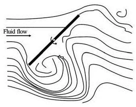
Fig.1 Schematic of flow-induced rotation of a flat plate hinged at the center and free to rotate in uniform current
According to Ref.[6], the motion characteristics of a freely falling and fixed-axis rectangular plate is determined by the Reynolds number, the aspect ratio, thickness ratio (the ratio of width to thickness of plate) and dimensionless moment of inertia of the flat plate. Actually the motion in free fall, and, in particular, the transition from fluttering to tumbling, should be completely governed by these parameters.
Field et al.[7]worked out a bifurcation diagram based on experimental data, which showed the dynamical behavior of falling disks as a function of the two parameters: the dimensionless moment of inertia and Reynolds number. According to that bifurcation diagram, the motion could be fluttering for smaller dimensionless moment of inertia, or tumbling for larger dimensionless moment of inertia. Based on these measurements, the transition from fluttering to tumbling is nearly independent of the Reynolds number and it appears atI*≅0.04, whereI*is the dimensionless moment of inertia.
Mittal et al.[8]showed a computational study on the flow-induced motion of a hinged plate pinned at its center. Their focus was on the effects of the Reynolds number and plate thickness ratio and non-dimensional moment of inertia on vortex-induced rotation of plates. Based on their numerical results, they suggested that the flutter and tumble frequencies of large aspect-ratio plates are governed by the Von-Kármán vortex shedding process. Anderen et al.[1]investigated the dynamics of freely falling plates experimentally, numerically and by quasi-steady modeling, at the Reynolds number of 103, which described the motion of freely falling rigid plates based on detailed measurements of the plate trajectories and from this to assess the instantaneous fluid forces.
In the present study, the flow-induced rotation of a fixed axis flat plate is studied experimentally and a bifurcation diagram prepared to classify the small fluttering, fluttering and autorotation motions based on different Reynolds numbers and dimensionless moments of inertia. The moment coefficients for different angles of attack of a fixed flat plate are determined by experiments and the streamline theory. These static results are used for stability analysis of flow-induced rotation.
1. Hydrodynamic forces and moments exerting on a flat plate
Flat plate is a simple airfoil which has no thickness or especial shape. For small incidence angles of attack, several results were recovered for inviscid and irrotational flow such as the classical results of vortex sheet approach to calculate loads acting on flat plate. But for large incidence angles, because of the presence of wake behind the plate, it is not possible to assume that the flow is inviscid and the viscous term plays an important role on the loads and moments acting on the plate. One of the methods used to attack the problem is the free-streamline theory.
The main objective of this theory is to find the free streamlines to define the wake, and the location of these free streamlines are initially unknown and must be found as a part of solution. Outside the wake region the flow is potential.
According to the experiments, the pressure on the free streamline does tend to remain constant for some distance downstream of the separation point[9,10]. The shear layers do not continue far downstream as was assumed and roll up to form vortices, alternately on each side. This vortex formation occurs behind all bluff bodies, at a frequency which is a characteristic of each body shape.
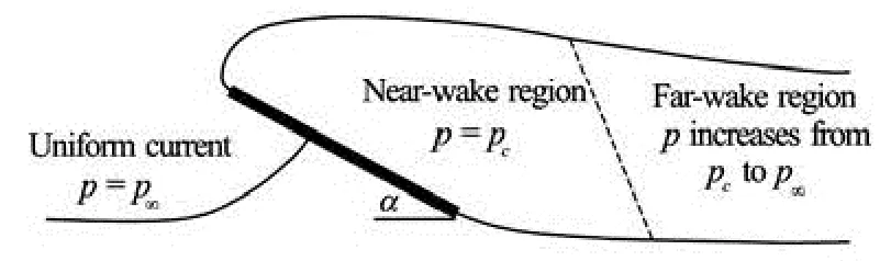
Fig.2 Schematic of free streamline theory for flow past a flat plate
The flow past a bluff body is considered in two parts (see Fig.2). Near the body it may be described by the free-streamline theory. As was mentioned above, the experiments show that, the pressure in a certain distance downstream of the separation points is approximately constant, this part of the wake will be called the near wake and the pressure in this region is constant. In the downstream regime of wake behind the near-wake region, the vortices mix and diffuse rapidly and eventually dissipate in the wake, and thispart of the wake is called the far wake, or the mixing range. Along the far wake the mean pressure increases gradually from the wake under-pressure and finally recovers the main stream pressure far downstream.
Kirchhoff was the first who proposed the idea of a wake bounded by free streamlines as a model for the flow behind a bluff body. According to his assumption, the velocity on the free streamline at separation is equal to the free-stream velocityU. In this case, the pressure at the separation points and behind the separation points is equal to the free-stream pressure, which it is a considerable loss of reality. Because it is not in agreement with experience, which shows that the pressure is actually always lower than the freestream value.
In this paper we will focus on the results of a modern view of free streamline theory by Wu[10]to calculate the loads and moment acting on a flat plate. Wu assumed that the pressure in the near-wake region (pc), is uniform and constant, which leads to a dimensionless equivalent parameter ofpc, usually called the wake under-pressure coefficient ()σ. This parameter characterizes the pressure of wake flow, based on free stream pressure. In fact, the different flow regimes of the fully and partially developed flows can also be indicated by different ranges ofσ.
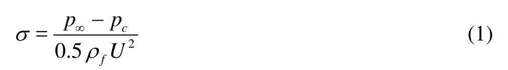
wherep∞denotes the pressure of the undisturbed free stream,Uthe flow velocity, andfρthe fluid density. The wake flow will be called fully developed, if the region of the constant-pressure near wake extends beyond the trailing edge of the plate and will be called partially developed, if the near-wake region terminates in front of the trailing edge.
According to Kirchhoff’s classical result, the normal coefficient (CN) of flow past a flat plate (σ=0) is rewritten as
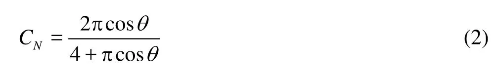
whereθis angle of attack and is equal to zero when the plate is vertical to the flow. In the fully wake flow past a flat plate, the local pressure is everywhere normal to the plate, and there is no singular force at the leading edge, thereforeCLandCDshould satisfy the condition
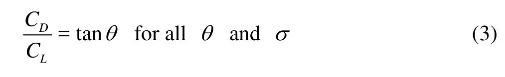
In the special cases of (1)σ=0 or (2)θclose to zero andσ>0, the condition (3) is obviously satisfied. Each angle of attack must be assumed a different bluff body, which has a different pressure in the downstream of separation points. But in the general case, because of the complicated manner in which the dependence onθandσappears, the results of streamline theory show that for the angleθsmaller than 45o, the values ofCLandCDapproach respectively the asymptotes[9,10]
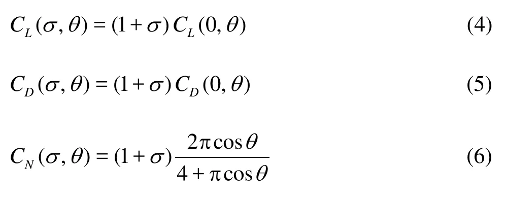
This argument is supported by experimental and numerical evidences. The loads and moment coefficients were measured for a fixed flat plate, as a function of different angles of attack by experiments in a flume (22 m×1.4 m×0.5 m) at the LOC-COPPE-UFRJ (Laboratory of Waves and Current of COPPE, Federal University of Rio de Janeiro). Similar measurements were carried out by the present authors with a CFD simulation using the ANSYS CFX code[3,5]. Figure 3 shows the comparison of normal coefficient of streamline theory withσ=1.25 and experimental results at LOC and Hoerner[11], and also numerical results given Fernandes et al.[3,5].
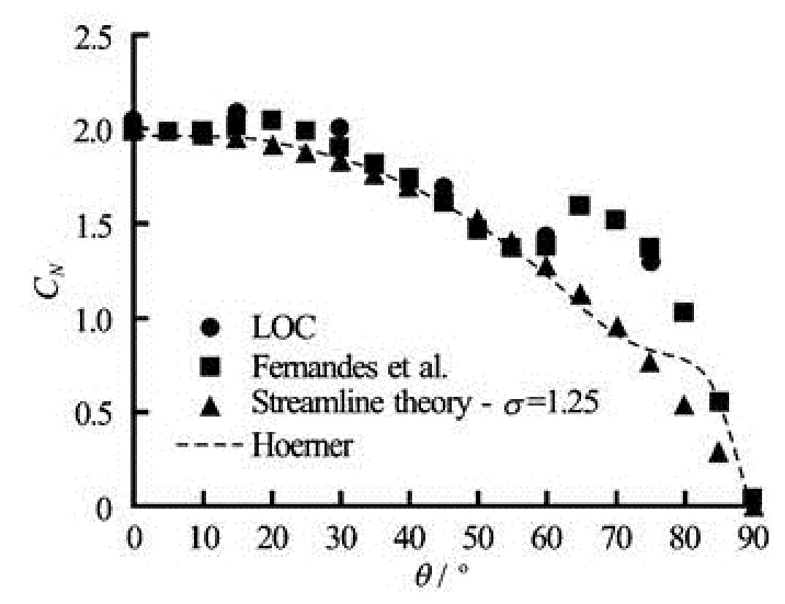
Fig.3 Normal force coefficient for a fixed flat plate
Figure 3 demonstrates that the results obtained with the streamline theory agree very well with numerical and experimental results. As was expected, because of constant pressure distribution on the wake side of the plate, the location of center of pressure is independent of the practical range ofσ. The constant pressure on the downstream side of plate makes the center of pressure of this side of plate always being inthe center of plate. Hence the overall center of pressure of plate only depends on the pressure distribution of upstream side of plate. By considering thatα=π/2-θ, Kirchhoff’s classical formulation for the center of pressure (c) in terms of the width (b) is[9,10]
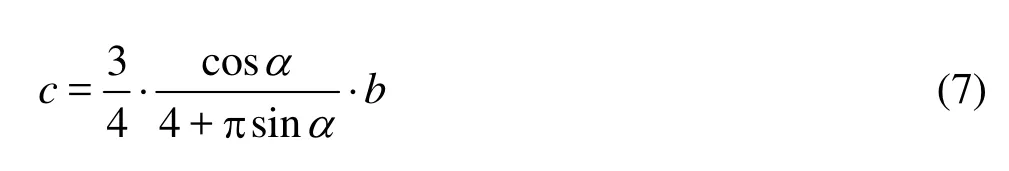
Based on above discussion, Kirchhoff’s classical formulation for the center of pressure (Eq.(7)) shows a good agreement with numerical results of Fernandes et al.[3,5]and experimental results of LOC, Flachsbart and Tachikawa, whenθis smaller than 70o(see Fig.4). The experimental data of Flachsbart and Tachikawa were reported by Holmes et al.[12].
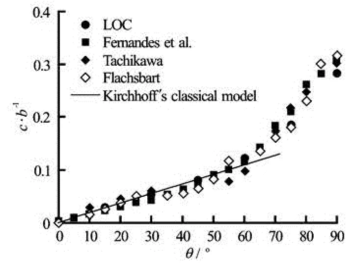
Fig.4 Position of the center of pressure for a fixed flat plat
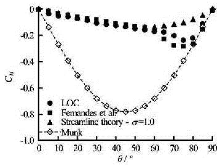
Fig.5 Moment coefficient for a fixed flat plate
The moment coefficient could be obtained from Eq.(7) for the center of pressure and Eq.(6) for normal coefficient. Hence, the moment coefficient formulation is
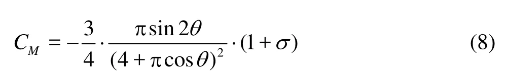
Figure 5 demonstrates the moment coefficients obtained by the experiment of LOC, streamline theory (Eq.(8)), Munk theory and numerical modeling of Fernandes et al.[3,5]. It shows the streamline theory works very well for the angles smaller than 60(θ<60o).
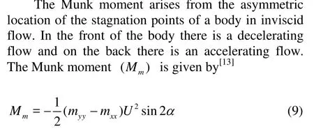
wheremxxis the added mass along the bodyx-axis (longitudinal), andmyyis along the body lateraly-axis (transversal). According to above statements, the Munk moment coefficient for a flat plate can be express as
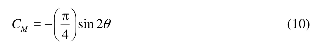
It can be concluded that, the Munk moment is accurate for calculation of the moment in the incidence angle range ofoo75≤θ≤90 where the stall does not happen and flow is inviscid. On the other hand, the streamline theory formulation could be used for angels of attack smaller than 75o(see Table 1).
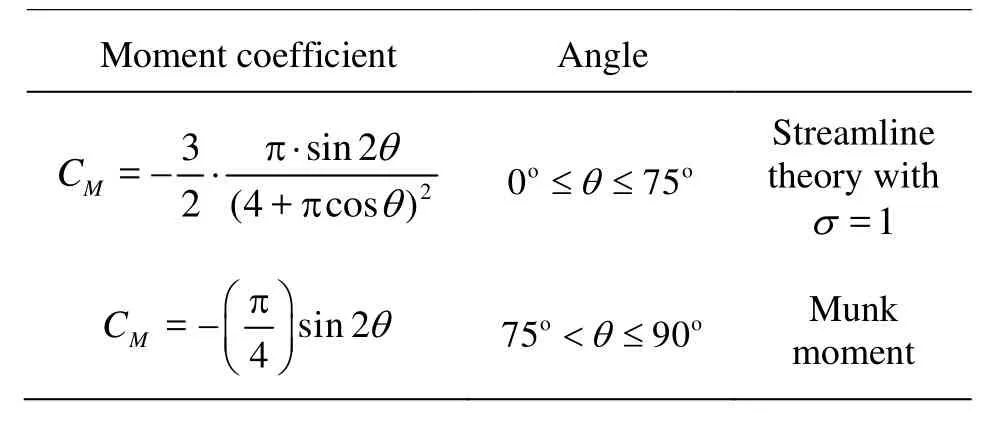
Table 1 List of moment coefficient segments
2. Flow-induced rotation
Based on the tests in the wind channels by pervious researchers[6,9]and also the experiments in LOC, it is proved that the autorotation occurs at large dimensionless moment of inertia.
2.1Experimental modeling
Several tests were performed at the LOC to investigate the flow-induced rotation of plates with different dimensionless moments of inertia and different Reynolds numbers. Three different behaviors could be devised experimentally: small fluttering state, fluttering and autorotation. In practice it was observed that when the plate is released at an angle smaller than the stall angle (approximately -15o≤α≤15o) and if the dimensionless moment of inertia is large enough, then the motion is affected by the large lift force and the autorotation will occur. On the other hand, if the plate releases from rest at an angular position in which the flow was stalled (approximately -75o≤θ≤75o), the plate starts to flutter around a stable position normal to the current. Therefore, the requirements for autorotation are: having a large enough moment of inertia to store sufficient angular moment and also a proper initial condition (angular position or velocity).
In water flume, because of large density of water in comparison of air, reaching to a certain dimensionless moment of inertia the occurrence of autorotation is difficult. For this purpose, as shown in Fig.6, in order to increase the moment of inertia of plate, a bar with length of 1 m installed on the top of plate. Also two masses added to system which could be placed in different levels of the bar to provide different moment of inertia.
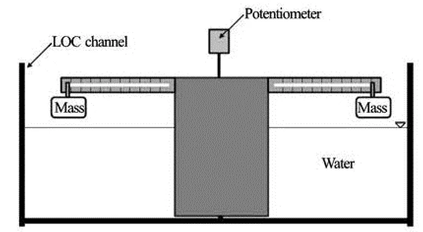
Fig.6 The experimental setup for autorotation motion
Based on the experiments at LOC, the bifurcation diagram is presented in Fig.7 as a function of the Reynolds number and dimensionless moment of inertia to classify the small fluttering state, fluttering and autorotation motions. It should be mentioned here that the small fluttering state is characterized by small oscillation angles in the range of -10o≤θ≤10o. Actually, it means that the small fluttering state is fluttering mootion with equivalent harmonic angle smaller than 10.
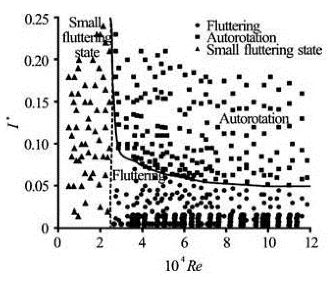
Fig.7 Bifurcation diagram to show dynamical behavior of flowinduced rotation based on Reynolds number and dimensionless moment of inertia, obtained by experiments at LOC. Each point means a different test
As is shown in Fig.7, at low Reynolds numbers (approximately smaller than 25 000), the plate stays almost at the same initial orientation (small fluttering state). At higher Reynolds numbers, depending on the dimensionless moment of inertia, the motion could be fluttering for smaller dimensionless moment of inertia, or autorotation (tumbling) for large dimensionless moment of inertia. Note that the transition from fluttering to autorotation is nearly independent of Reynolds number and it appears atI*=0.05 to 0.06, which is close to the falling disc case reported by Field et al.[7](I*≅0.04).
This similarity between the results of our experimental model with 1-DOF and other 3-DOF models[7]allows us to use this simpler configuration case (1-DOF) for replacing 3-DOF models.
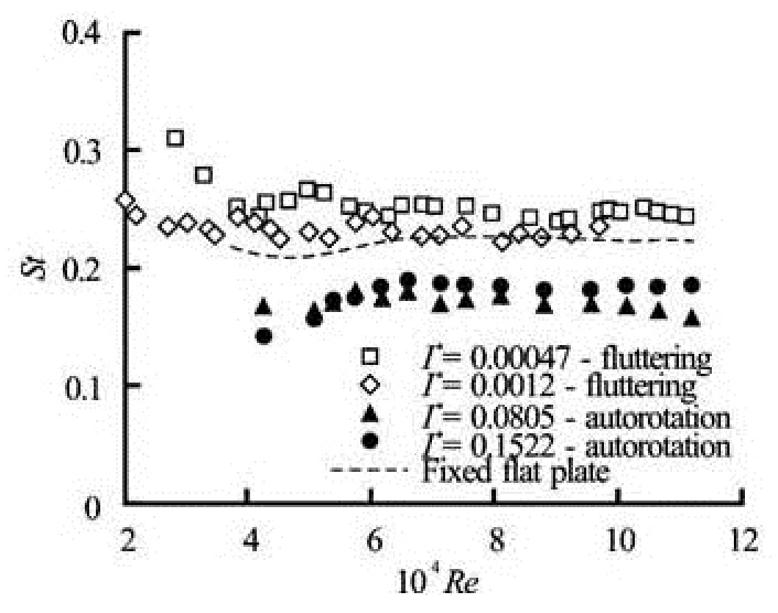
Fig.8 Strouhal number versus Reynolds number for different cases
Experiments at the LOC proved that with increasing Reynolds number, the angular amplitude in fluttering motion increases and the angular velocity ofautorotation tends to a constant with smaller fluctuation component. The dimensional analysis performed by authors[4,5]indicate that the response frequency of flow-induced rotation of a flat plate is linearly proportional to the incoming velocityUand inversely proportional to the plate widthb. This statement is confirmed by experiments performed at the LOC. Figure 8 demonstrates the Strouhal number for fluttering, autorotation and also normal fixed flat plate against the Reynolds number. The Strouhal number is a dimensionless number characterizing the frequency as given by
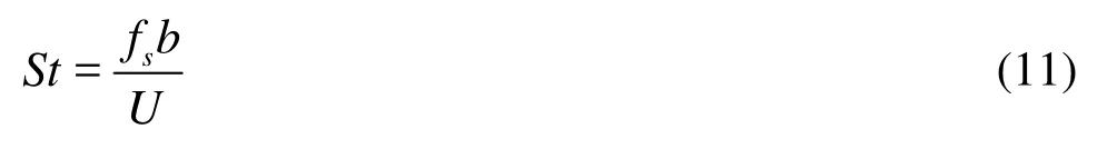
wherefsis the frequency of vortex shedding for fixed plate and response frequency for fluttering and autorotation motions. The measurements show that the vortex shedding frequency and the fluttering response frequency are almost identical (with a difference smaller than 5% in value). In autorotation motion, by increasing the amplitude of rotation, the difference of vortex shedding frequency and response frequency increases, however they are still in a good agreement. In other words, it is clear that the fluttering and autorotation of the plate is a result of an angular moment due to the vortex shedding of plate.
2.2Stability analysis
To gain further insight into the nature of transition between fluttering and autorotation, we considered a phenomenological model of the flow-induced rotation for a flat plate hinged at center. The aim of this section is to conduct a simple stability analysis. An un-damped linear model for the flow-induced rotation of a flat plate in a uniform current is suggested by applying the angular moment theorem (it is the case of only one degree of freedom)
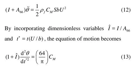
This equation can be solved numerically using the fourth-order Runge-Kutta method. The normal force coefficient and center of pressure positions obtained for static plates at various angles of attack are used to obtain moment coefficients (Table 1). With the moment coefficient proposed from the streamline theory and Munk, the obtained equations of motion are shown in Table 2.
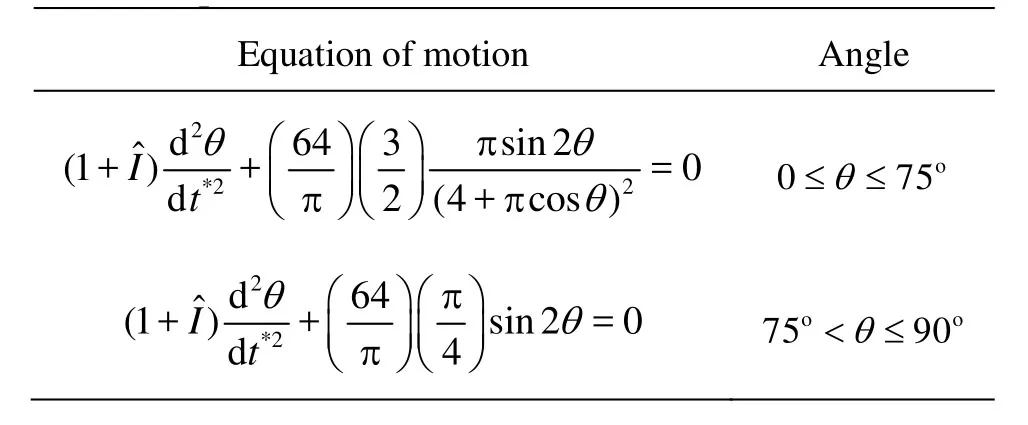
Table 2 Equations of motion for flow induced rotation
The fixed points for differential equation models of motion are (θ,ω)=(nπ/2,0),n=0,±1,±2…, ±∞. For linearization of equations of motion of Table 2, to obtain a system of ODEs, we setθ=y1,ω=y2and also considered the Maclaurin series. According to stability analysis on the linearized equations in the neighborhood of the fixed points, we can express that, whenn=0,±2,±4,… the critical points are all Centers, and on the other hand the critical points with odd value ofnare all Saddle points. The conservative energy system for differential equation model of flow-induced rotation motion is
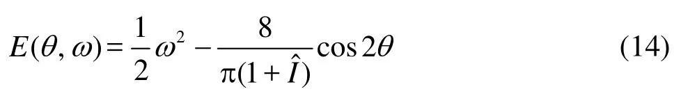
Furthermore, since the unique solution of an initial value problem goes through each point in the (θ, )ω, every level curve represents the trajectory of a solution. Hence, each trajectory in Fig.9 lies at an energy level of system. The phase diagram of flow induced rotation problem (Fig.9) is very similar to the phase portrait for the un-damped pendulum equation.
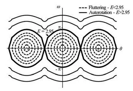
Fig.9 The phase diagram of flow induced rotation for various values ofE
The initial value problems have a unique solution that depends on initial conditions, in fact, different initial conditions can induce different modes of oscillations (fluttering or autorotation). This statement is also verified by experiments: the autorotation occurs onlywhen the energy level is large enough which depends on dimensionless moment of inertia and initial conditions (angle and angular velocity).
These graphs continue periodically with period π to the left and right. We can see some of the trajectories are ellipse-like and closed (fluttering motion) and some other are wavy (autorotation motion). Each periodic orbit of fluttering and autorotation are bounded by a pair of harmonic orbits which form the sepatrix. For<2.95, the plate oscillates about the centerθ=0. For>2.95, the plate has a whirly motion that appears as wavy trajectories in the phase diagram (autorotation), and the angular velocity of autorotation is almost constant with a small oscillatory component. Finally, the valueE=2.9 corresponds to the two “separating trajectories” in Fig.9 connecting the saddle points.
Considering the damping term in dynamical model will be a challenge for future of this research. The damping term in the problem of flow-induced rotation generally consists of two terms: physical damping and damping due to the hydrodynamics. The physical damping results in an energy loss due to the structural friction and it use for energy extraction systems. On the other hand, the hydrodynamic damping terms considered by other investigators[1,16,17]depends on the current speed, and its value changes as the speed changes.
3. Conclusions
The behavior of flow-induced rotation of a vertical flat plate which is free to rotate in uniform current is presented in this paper. The loads and moment coefficient formulations have been suggested by considering streamline theory for different angles of attack. The streamline theory results have been validated by experimental and numerical results.
The dimensional analysis proves that the motion in flow-induced rotation and in particular, the transition from fluttering to autorotation, should be completely governed by the dimensionless moment of inertia (I*) and Reynolds number (Re). The small fluttering state motion occurs at the Reynolds number smaller than 25 000, which the plate stays at the same initial orientation. For larger Reynolds numbers, the transition from fluttering to autorotation is nearly independent to Reynolds number and it appears atI*=0.05 to 0.06. Based on an un-damped dynamical model for flow induced rotation, a stability analysis has been performed. The system looks conservative. The amount of energy that separates the fluttering from autorotation is identified.
Acknowledgements
The authors express their thanks to CNPq (Brazilian National Research Council), ANP (Brazilian National Petroleum Agency) and LOC/ COPPE/UFRJ (Laboratory of Waves and Current of COPPE, Federal University of Rio de Janeiro).
[1] ANDERSEN V., PESAVENTO U. and WANG Z. J. Analysis of transitions between fluttering, tumbling and steady descent of falling cards[J]. Journal of Fluid Mechanics, 2005, 541: 91-104.
[2] PESAVENTO U., WANG Z. J. Falling paper: Navier-Stokes solutions, model of fluid forces, and center of mass elevation[J]. Journal of Physical Review Letters, 2004, 93(14): 144501.
[3] FERNANDES A. C., MIRZAEI SEFAT S. Flow induced fluttering and autorotation of a hinged vertical flat plate[C]. Proceedings of the ASME, 31st International Conference of Ocean, Offshore and Arctic Engineering, Rio de Janeiro, Brazil, 2012.
[4] FERNANDES A. C., MIRZAEI SEFAT S. and COELHO F. M. et al. Experimental investigation of flow induced rotation of hinged plates with shapes to avoid fluttering[C]. Proceedings of the ASME, 30th International Conference of Ocean, Offshore and Arctic Engineering. Rotterdam, The Netherlands, 2011.
[5] FERNANDES A. C., MIRZAEI SEFAT S. and COELHO F. M. et al. Towards the understanding of manifold fluttering during pendulous installation: Induced rotation of flat plates in uniform flow[C]. Proceedings of the ASME, 29th International Conference of Ocean, Offshore and Arctic Engineering. Shanghai, China, 2010.
[6] IVERSEN J. D. Autorotating flat-plate wings: The effect of the moment of inertia, geometry and Reynolds number[J]. Journal of Fluid Mechanics, 1979, 92: 327-348.
[7] FIELD S. B., KLAUS M. and MOORE M. G. et al. Chaotic dynamics of falling disks[J]. Nature, 1997, 388: 252-254.
[8] MITTAL R., SESHADRI V. and UDAYKUMAR H. S. Flutter, tumble and vortex induced autorotation[J]. Journal of Theoretical and Computational Fluid Dynamics, 2004, 17(3): 165-170.
[9] MIRZAEI SEFAT S., FERNANDES A. C. Flow induced rotation of a flat plate subjected in uniform current based on the streamline theory[C]. Proceedings of the ASME, 30th International Conference of Ocean, Offshore and Arctic Engineering. Rotterdam, The Netherlands, 2011.
[10] WU T. Y., WANG D. P. A wake model for free-streamline flow theory Part 2. Cavity flows past obstacles of arbitrary profile[J]. Journal of Fluid Mechanics, 1964, 18(1): 65-93.
[11] HOERNER S. F. Fluid-dynamic drag[M]. Published by Author, 1965, 20.
[12] HOLMES J. D., LETCHFORD C. W. and LIN N. Investigations of plate-type windborne debris-Part II: Computed trajectories[J]. Journal of Wind Engineering and Industrial Aerodynamics, 2006, 94(1): 21-39.
[13] TRIANTAFYLLOU M. S., HOVER F. S. Maneuvering and control of marine vehicles[M]. Cambirdge, Massachusetts, USA: Massachusetts Institute of Technology, 2002, 25.
[14] SESHADRI V., MITTAL R. and UDAYKUMAR H. S. Vortex induced auto-rotation of a hinged plate: A computational study[C]. Proceedings of the ASME, 4th Conference of International Fluid Engineering Division Summer Meeting FEDSM. Honolulu, Hawaii, USA, 2003.
[15] ARMANDEI M., FERNANDES A. C. Passive energy extraction through oscillation of a yawing flat plate operating in a uniform current[C]. Proceedings of the ASME, 30th International Conference of Ocean, Offshore and Arctic Engineering. Rotterdam, The Netherlands, 2011.
[16] ARMANDEI M., FERNANDES A. C. Marine current energy using torsional galloping based turbine[C]. 2013 Offshore Technology Conference. Houston, TX, USA, 2013.
[17] BAKER C. J. The debris flight equations[J]. Journal of Wind Engineering and Industrial Aerodynamics, 2007, 95(5): 329-353.
10.1016/S1001-6058(13)60422-9
* Biography: MIRZAEISEFAT Sina (1983-), Male, Postdoctoral Researcher
杂志排行

水动力学研究与进展 B辑的其它文章
- A one-dimensional polynomial chaos method in CFD–Based uncertainty quantification for ship hydrodynamic performance*
- Numerical analysis of cavitation within slanted axial-flow pump*
- Numerical simulation of hydro-elastic problems with smoothed particle hydrodynamics method*
- Analytic solutions of the interstitial fluid flow models*
- Experimental study of shell side flow-induced vibration of conical spiral tube bundle*
- A streamline approach for identification of the flowing and stagnant zones for five-spot well patterns in low permeability reservoirs*