A streamline approach for identification of the flowing and stagnant zones for five-spot well patterns in low permeability reservoirs*
2013-06-01LUOWanjing罗万静
LUO Wan-jing (罗万静)
School of Energy, China University of Geosciences, Beijing, 100083, China, E-mail: luowanjing@qq.com WANG Jun-lei (王军磊)
Petro China Research Institute of Petroleum Exploration and Development, Beijing 100083, China
WANG Xiao-dong (王晓冬)
School of Energy, China University of Geosciences, Beijing 100083, China
ZHOU Ying-fang (周英芳)
International Research Institute of Stavanger, Stavanger 4068, Norway
(Received September 16, 2012, Revised March 11, 2013)
A streamline approach for identification of the flowing and stagnant zones for five-spot well patterns in low permeability reservoirs*
LUO Wan-jing (罗万静)
School of Energy, China University of Geosciences, Beijing, 100083, China, E-mail: luowanjing@qq.com WANG Jun-lei (王军磊)
Petro China Research Institute of Petroleum Exploration and Development, Beijing 100083, China
WANG Xiao-dong (王晓冬)
School of Energy, China University of Geosciences, Beijing 100083, China
ZHOU Ying-fang (周英芳)
International Research Institute of Stavanger, Stavanger 4068, Norway
(Received September 16, 2012, Revised March 11, 2013)
The mechanism of the fluid flow in low permeability reservoirs is different from that in middle-high permeability reservoirs because of the existence of the Threshold Pressure Gradient (TPG). When the pressure gradient at some location is greater than the TPG, the fluid in porous media begins to flow. By applying the mirror image method and the principle of potential superposition, the steady-state pressure distribution and the stream function for infinite five-spot well patterns can be obtained for a low permeability reservoir with the TPG effect. Based on the streamlines distribution, the flowing and stagnant zones in five-spot well patterns can be clearly seen. By the definition of the effective startup coefficient (SUC), the ratio of the flowing and stagnant zones can be calculated accurately. It is shown that the SUC for five-spot well patterns is not constant, but decreases with the increase of the dimensionless TPG. By increasing the effective permeability of the formation (such as by the acid treatment and the hydraulic fracture), in increasing the injection-production differential pressure or shortening the well space (such as by infilling well), the SUC can be improved. The results of the sensitivity analysis show that a better choice for the SUC enhancement is to shorten the well spacing for small permeability reservoirs and to increase the pressure difference for large permeability reservoirs. This streamline approach can be used to determine the distribution of remaining oil and provide guidance for infilling well.
low permeability reservoir, Threshold Pressure Gradient (TPG), streamlines simulation, five-spot well patterns, effective startup coefficient
Introduction
In recent decades, the studies of unconventional reservoirs (such as low-ultra permeability reservoir, shale gas, coal bed methane gas) received a great deal of attention because of its important industrial applications in the petroleum industry.
For low permeability reservoirs, the seepage flow mechanism and its behavior are relatively abnormal because of tiny pores and throats, large specific surface, strong interfacial tension between solid and liquid and thick boundary layer of oil. In recent years, Song et al.[1]found the existence of the Threshold Pressure Gradient (TPG) in the microchannel and the relation between the TPG and the diameter in a singlelog normalization. Hao et al.[2], Zeng et al.[3]simulated oil, formation water, injected water, and distillated water as displacing fluids to measure and analyze the TPG for both a single- and two-phase fluid flow. He pointed out that due to the capillary pressure and the Jamin effect, the TPG for a two-phase oil and water flow is greater than that for a single-phase flow. Song et al.[4]tested the TPG of microchannels with boundary surfaces of different wettabilities and it is shown that the resistance of the liquid flow can be reduced by changing the wettability of the boundary surfaces. Theinfluence of fluid physicochemical properties on the threshold pressure gradient was investigated in the laboratory and the mechanism of the TPG reduction by surfactant was analyzed by Cheng et al.[5]Song et al.[6,7]simulated the gas flow in water-bearing tight gas reservoirs in experiment. He concluded that the TPG increases with the increase of the water saturation and the decrease of the absolute permeability and the peripheral reserves of the wellbore are difficult to deploy because of the existence of the TPG. Song et al.[8]suggested that the higher the TPG, the smaller the formation pressure of the water-bearing tight gas reservoir spread. In the same output, the reservoir sweep of the non-Darcy gas flow is larger than that of the non-Darcy liquid flow.
With respect to the TPG effect for a 5-spot well pattern, Ji[9]suggested that only a part of the reservoir can be developed, which means that some oil can flow while the other is stagnant. He supposed that the streamline of the fluid flow is a broken line instead of a continuous curve and put forward the concept of the startup coefficient (SUC) to characterize the startup degree of the reservoir in different well patterns. Zhu[10]presented a relative simple calculation method of the control radius in a single well system and applied it into five-spot well patterns to approximately analyze the startup degree of a low permeability reservoir.
These methods are approximate and have simplified the fluid flow in the porous media. They cannot be used to evaluate the real flowing zone and stagnant zone accurately. This paper presents non-homogeneous mathematical equations for the TPG effect. A streamline approach is used to identify flowing and stagnant zones. An integral method of estimating the flowing zone is developed based on the stream function. Then, the SUC can be obtained for five-spot well patterns.
1. Mechanism of fluid flow in low permeability porous media
In low permeability reservoirs, the fluid flow through the porous media is nonlinear. Combining the Muskat’s assumptions[11]and the modified Darcy’s law, the mathematical model of low permeability reservoirs can be established.
In Cartesian coordinates, the modified Darcy law with the TPG takes the form
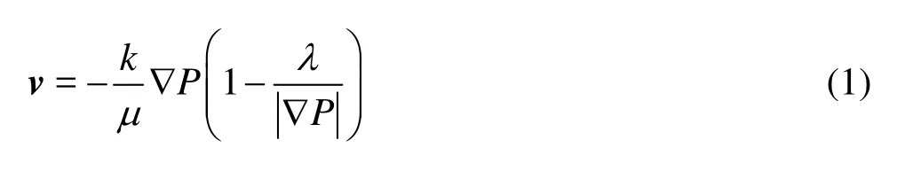
wherevis the velocity of flow in porous media,kis the reservoir permeability,μis the oil viscosity,λis the TPG.
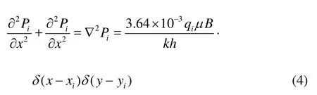
In a multi-well system of the isotropic reservoir, we define the coordinates of theith well asxwiandywi. So the mass conservation law with source/sink terms is expressed as,
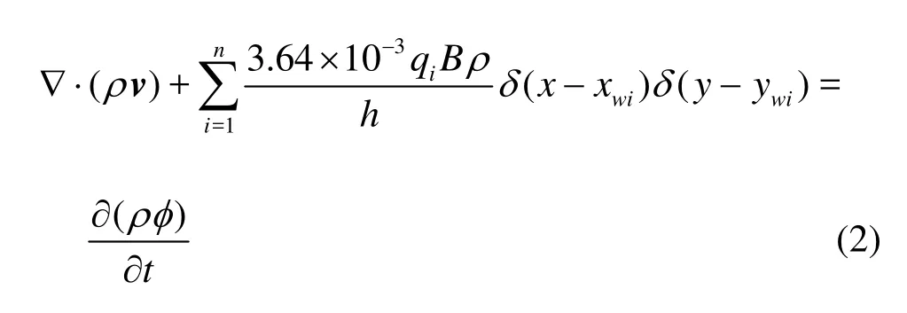
Herehis the reservoir thickness,qiis the ith injection/production rate,xwiis theith location inx-axis coordinate,ywiis theith location iny-axis coordinate,Bis the oil volume factor,φis the reservoir porosity,ρis the fluid density,δis the delta function,xis the distance inx-drection,yis the distance iny-drection.
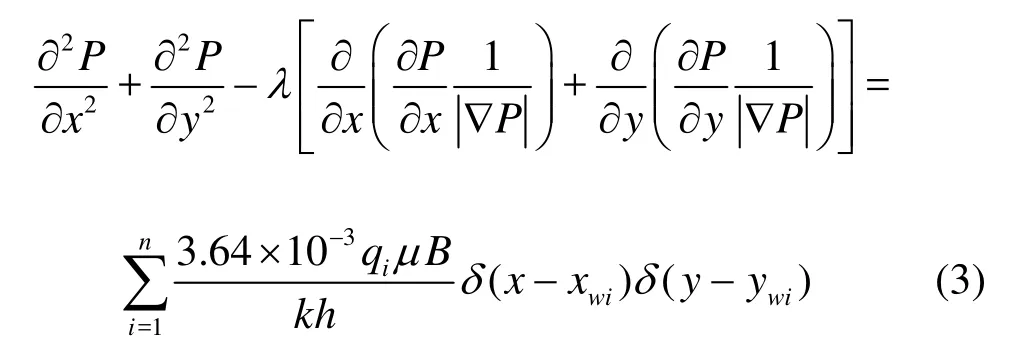
In the process of waterflooding, the elastic energies of the fluid and the rock are exhausted out, soρandφare constants and the flow in the porous media is in a steady state.
Substituting Eq.(1) into Eq.(2), the pressure formulation of the multi-wells system is as follows,
Equation (3) is the same as that for conventional reservoirs, which consists of a sum ofiP, namely
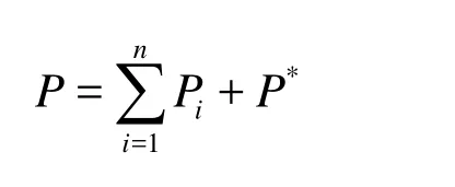
whereiPis the general solution of theith differential equation,P*is a particular solution of Eq.(3).
Therefore theith differential equation and the general solution are expressed as,
Then+1thequation is
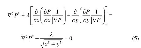
Utilizing the Green formula, the solution of Eq.(4) could be expressed as
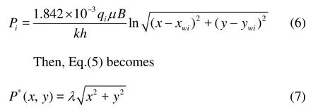
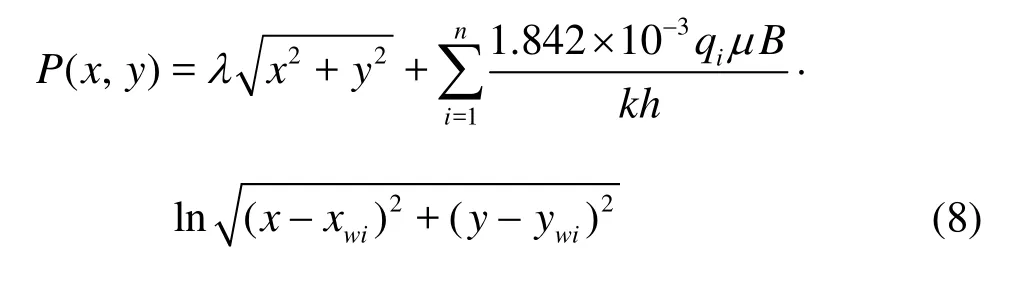
Therefore, according to the classical steady state flow theory, the solution of Eq.(3) is expressed as
For five-spot well patterns, the production and the injection are in an alternate arrangement (Fig.1). Choosing an injector as the origin of coordinates, Cartesian coordinates can be established. The area encircled by the broken line is a well pattern unit and the shadow area is a quarter-well pattern unit.
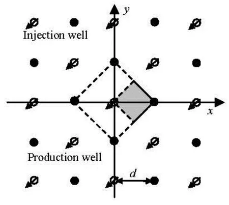
Fig.1 Schematic diagram of five-spot well patterns
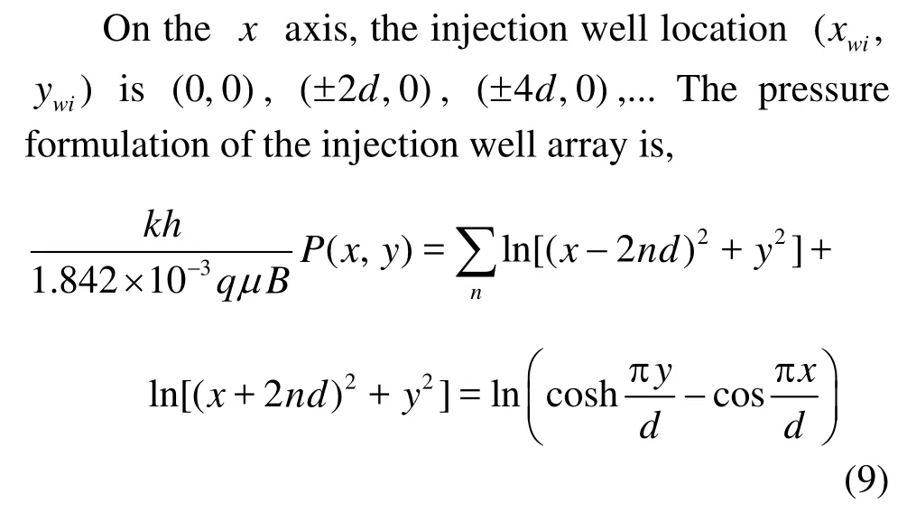
If the well array is a production well array, thenq=-q. Based on Eq.(8) and Eq.(9), in five-spot well patterns, the steady state pressure formulation can be expressed as,
wheremis the number of the well arrays,dis the injector-producer distance,rwis the well radius,ePis the initial formation pressure.
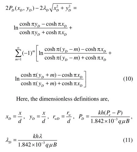
With the definition of the dimensionless pressure, according to Eq.(10), a linear relation exits between the well production rateqand the injection/production well pressure difference ΔP, which is

whereJis the productivity index of five-spot well patterns, which is expressed as
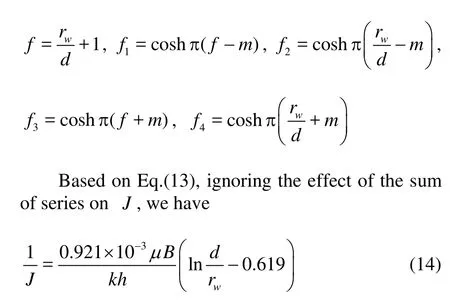
There are three main parameters that can have effects on the production rateq, namely, the well spacingd, the threshold pressure gradientλand the pressure difference ΔP.
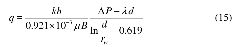
Equation (15) is consistent with the results obtained by Luo et al.[12].
2. Identification of flowing and stagnant zones in five-spot well patterns
The streamline visually tracks the movement of a specific particle along an appropriate path line. Every streamline starts at the injection well and ends at the production well. The particle tracking[13]and the analytical stream function[14]are conventional tools to generate streamlines. For analytical solutions, the velocity vector field is obtained directly from the analytical pressure field.
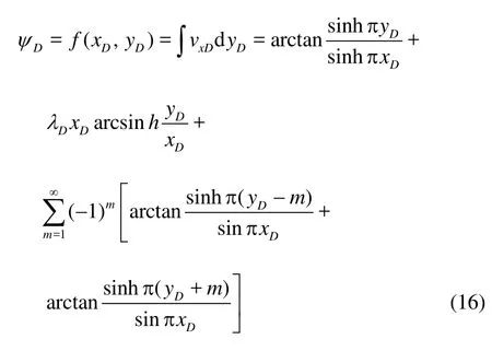
Because the stream function comes from the velocity field, the stream function for five-spot well patterns can be obtained by integratingvxDwith respect toyDaccording to the characteristics of the streamline, where, the flow velocity vector field in thex-direction is obtained by utilizing the modified Darcy’s law. WhenΨDis a constant, Eq.(16) gives directly a streamline. On the starting circle,xD→0 andyD→0, Eq.(16) can be approximately rewritten as
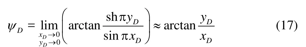
ThenyD=xDtan(ΨD).The value ofΨDindicates the included angle between the particle on the starting circle andx-axis. Because of the symmetry, we can focus on the eighth well pattern unit (triangle shadow area in Fig.1).
In a specific reservoir (TPG takes a fixed value), a series of streamlines between the injection well and the production well can be obtained in the 1/8 well pattern unit.
Step 1: The value ofΨDranges from 0 to π/4. For a specific value ofΨD, on a special streamline, we have

It should be pointed out that the streamline ofDΨcorresponding to π/4 is called the boundary streamline. The oil particles can be driven by the water particles in the region between the boundary streamline and the main streamline (the straight line connecting the producer and injector), thus this region is called the flowing zone and the rest of the region is called the stagnant zone (Fig.2).
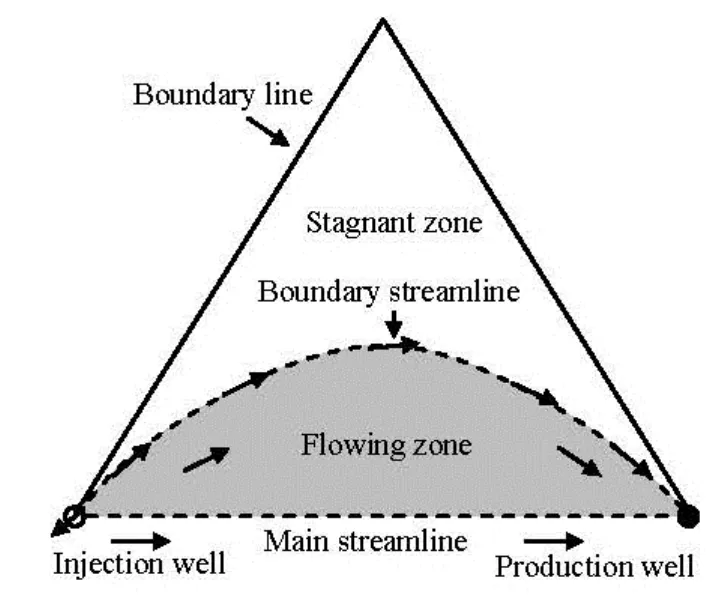
Fig.2 Flowing zone and stagnant zone with TPG in eighth unit
Step 2: The path of a streamline is obtained by finding the solution of Eq.(18). Then, a series of streamlines can be obtained sequentially.
In order to illustrate the stagnant zone and the flowing zone in detail, we map out the streamlines in a well pattern unit (Fig.3) for different dimensionlessTPGs. The flowing zone corresponds to the region covered by streamlines (dashed lines), while the rest is the stagnant zone.
It is shown from Fig.3 that for a conventional reservoir (TPG=0), all oil will be produced except the irreducible oil (Fig.3(a)). With TPG increasing, the area of the stagnant zone increases (Figs.3(b) and 3(c)). This phenomenon can be explained by the fact that the value of the displacement pressure gradient on some location is less than the TPG, so the fluid cannot flow and becomes the residual oil. Under the same injection-production conditions, the larger dimensionless TPG, the richer the residual oil will be.
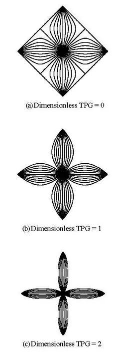
Fig.3 Streamlines with different dimensionless TPG for fivespot well pattern unit
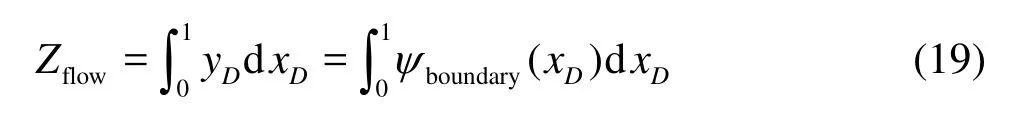
Therefore, the existence of TPG will reduce the effective startup zone, namely, the flowing zone, in low permeability reservoirs. We define the startup coefficient (SUC) as the ratio of the flowing zone (Zflow) to the whole well pattern unit (Zwhole=Zflow+Zstagnant).
Zflowis the area of the flowing zone which can be calculated as follows,
ψboundary(xD)refers to the boundary stream function, which is expressed in five-spot well patterns as
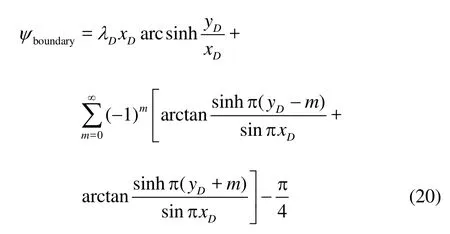
Figure 4 shows the relationship between the SUC and the dimensionless TPG. When the dimensionless TPG is equal to zero, the SUC is the one which means that the whole well pattern unit could be developed (Fig.3(a)). As seen from Fig.4, the SUC has a decreasing trend while the dimensionless TPG is going up, but the slope of the curve becomes smaller gradually.
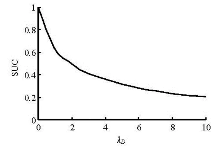
Fig.4 Dimensionless TPG vs SUC
3. Discussion
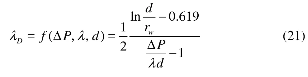
Combining the equations from Eqs.(11) to (15) yields the relationship ofDλ,λ,dand ΔPas follows In order to improve theSUC, we should decrease the dimensionless TPG. So, the following methods can be used to enhance the recovery of low permeability reservoirs.
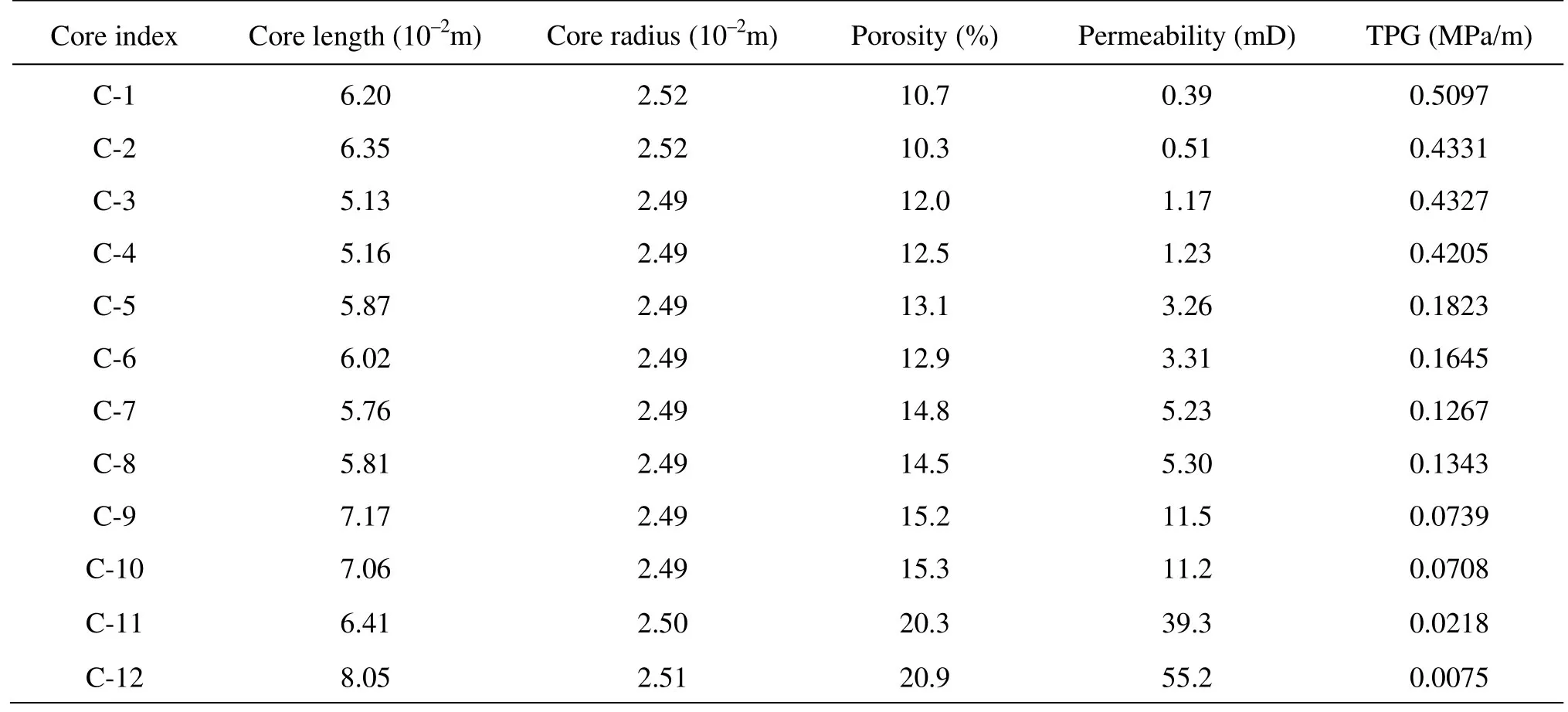
Table 1 Parameters of core analysis and experimental TPGs based on some oilfields
3.1Increasing the effective permeability
The existence of TPG can be explained by the wettabilitiy of the boundary surface and the boundary layer caused by the interaction between solid and fluid. In practice, a power regression relation exits between the TPG and the permeability, that is, TPG=ak-n[15-17]. Generally speaking, the effective permeability could be improved by the acid treatment and the hydraulic fracture.
3.2Shortening well spacing
For a low permeability reservoir, the shortening of the well spacing and the infilling of the well in the stagnant zone are effective to enhance the recovery. This method is used widely in China for the adjustment of the middle-late well patterns.
3.3Increasing the pressure difference between inje
ctor and producer
In order to overcome the extra flow resistance caused by the TPG, one might enhance the pressure difference between the injection well and the production well. However, the pressure difference could not be set without a limit under technological and geological conditions. Generally speaking, the wellbore pressure of the production well should be greater than the bubble pressure while the injecting wellbore pressure is lower than the formation breakdown pressure.
According to the relation between dimensionless TPG and SUC as shown in Fig.4, shorting well spacing and increasing permeability and raising pressure difference enhance the SUC, but the sensitivity of the SUC to the pressure difference and the well spacing depend on the permeability in the low permeability region. For some specific reservoir (permeability is fixed and constant), the best adjustment case, which means either adjusting the well spacing or the pressure difference, depends on the value of permeability. Here is an example of some oilfields in China to illustrate this sensitivity phenomenon.
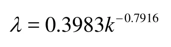
A regression relationship between the permeability and the TPG is derived from the above data (Table 1), which takes the form
In some oilfields, the average formation thickness is 5 m, the oil viscosity is 5 mPa/s, and there are 8 classical low permeability areas, separately 0.67 mD, 0.83 mD, 1.08 mD, 1.26 mD, 1.51 mD, 1.87 mD, 2.42 mD, 5.45 mD. The well spacing could be adjusted between 100 and 600m and the pressure difference varies between 5 MPa and 20 MPa.
3.3.1 Effect of well spacing
Under the conditions of fixed permeability and pressure difference, Fig.5(a) presents an inverse correlation of the SUC and the well spacing. In a reservoir with small permeability (permeability is 0.67 mD and 0.83 mD in this case), the absolute value of the curve slope is larger than that with a larger permeability. This means the SUC could be enhanced significantly through infilling well spacing in low permeability reservoir with small permeability.
3.3.2 Effect of pressure difference
Figure 5(b) illustrates a similar phenomenon as Fig.5(a). However, there exits a positive correlation between SUC and pressure difference. In low permeability reservoir with large permeability (such as permeability is 5.45 mD), raising pressure difference is a more effective method to enhance SUC.
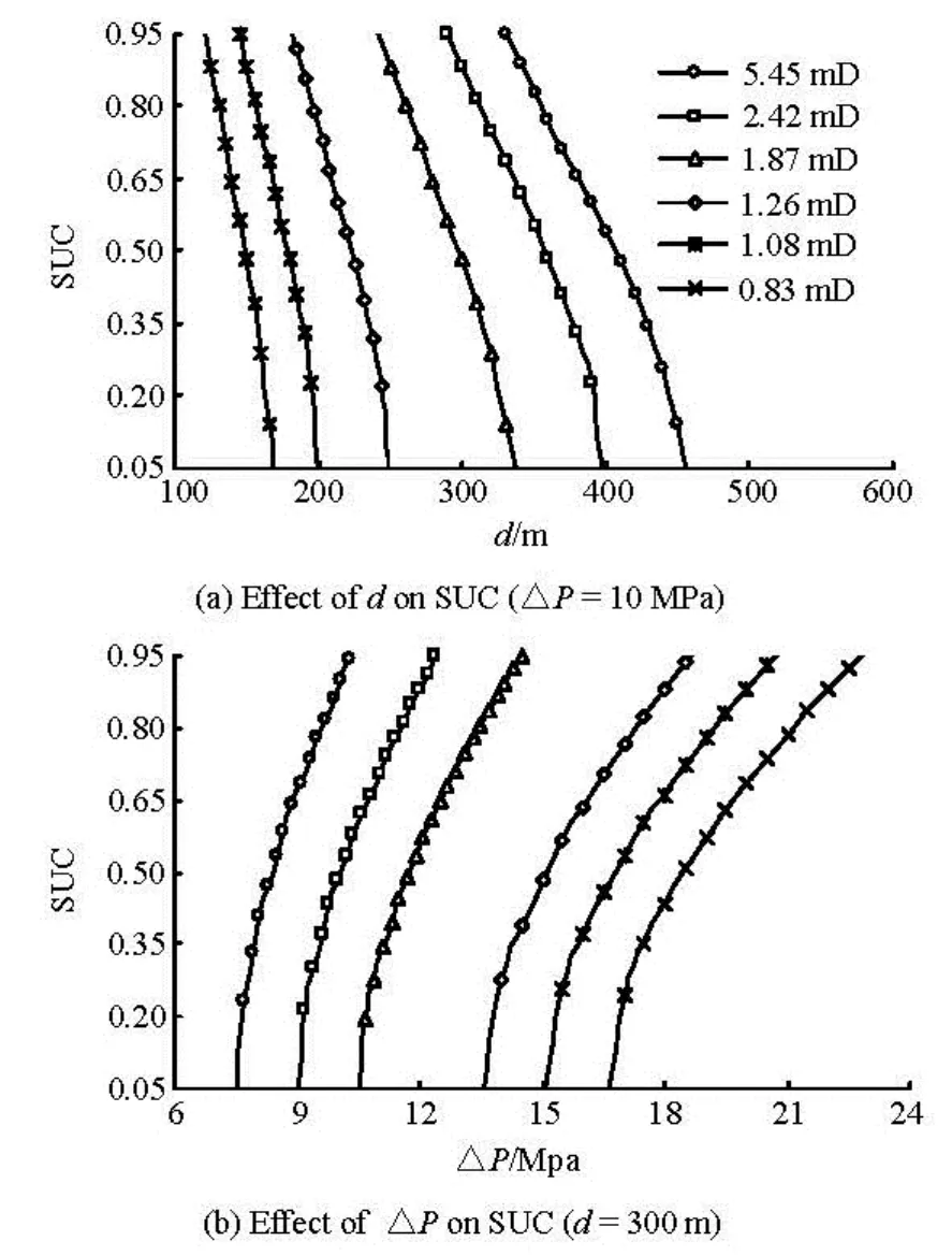
Fig.5 Type curves of effective development coefficient vs. TPG
4. Conclusions
In this study, the non-homogeneous equations for describing the fluid flow in low permeability reservoir are derived. By applying the mirror image method and the principle of potential superposition, the steadystate pressure distribution, the velocity formula and the stream function for infinite five-spot well patterns are obtained with consideration of the TPG. The final conclusions are as follows:
(1) The mechanism of the fluid flow in low permeability reservoirs is different from that in middlehigh permeability reservoirs because of the existence of the TPG. Only when the production pressure gradient is greater than the TPG, the fluid in porous media may begin to flow.
(2) For low permeability reservoirs, the streamline cannot spread all over the five-spot well patterns because of the existence of the TPG. It is shown that the SUC for five-spot well patterns is not constant, but decreasing with the increase of the dimensionless permeability. In order to improve the SUC, the acid treatment and the hydraulic fracture, in increasing the injection-production differential pressure and shortening the well space (by infilling well) can be put into practice.
(3) The results of sensitivity analysis show that a better choose for the SUC enhancement is to shorten the well spacing for small permeability reservoirs and to increase the pressure difference for large permeability reservoirs.
(4) This paper presents a new method for the identification of the flowing and stagnant zones in fivespot well patterns. It can be used to determine the distribution of the remaining oil and provide guidance for infilling well.
[1] SONG Fu-quan, JIANG Ren-jie and BIAN Shu-li. Measurement of threshold pressure gradient of microchannels by static method[J]. Chinese Physics Letters, 2007, 24(7): 1995-1998.
[2] HAO F., CHENG L. S. and HASSAN O. et al. Threshold pressure gradient in ultra-low permeability reservoirs[J]. Petroleum Science and Technology, 2008, 26(9): 1024-1035.
[3] ZENG B., CHENG L. and HAO F. Experiment and mechanism analysis on threshold pressure gradient with different fluids[C]. SPE 140678. Tinapa-Calabar, Nigeria, 2010.
[4] SONG Fu-quan, WANG Jian-dong and LIU Hai-li. Static threshold pressure gradient characteristics of liquid influenced by boundary wettability[J]. Chinese Physics Letters, 2010, 27(2): 024704.
[5] CHENG Lin-song, ZENG Bao-quan and HAO Fei. Mechanism of threshold pressure gradient reduction by surfactant[C]. Flow in Porous Media-from Phenomena to Engineering and Beyond. Wuhan, China, 2009, 170-174.
[6] ZHU W., SONG H. and HUANG X. et al. Pressure characteristics and effective deployment in a water-bearing tight gas reservoir with low-velocity non-Darcy flow[J]. Energy and Fuels, 2011, 25(3): 1111-1117.
[7] SONG Hong-qing, YUE Ming and ZHU Wei-yao et al. Formation pressure analysis of water-bearing tight gas reservoirs with unsteady low-velocity Non-Darcy flow[C]. 2nd International Conference on Manufacturing Science and Engineering. Guilin, China, 2011.
[8] SONG H. Q., ZHU W. Y. and WANG M. et al. A study of effective deployment in ultra-low-permeability reservoirs with non-Darcy flow[J]. Petroleum Science and Technology, 2010, 28(16): 1700-1711.
[9] JI Bing-yu, LI Li and WANG Chun-yan. Oil production calculation for areal well pattern of low-permeability reservoir with non-Darcy seepage flow[J]. Acta petroleum sinica, 2008, 29(2): 256-261(in Chinese).
[10] ZHU Wei-yao, LIU Jin-zi and SONG Hong-qiang et al. Calculation of effective startup degree of non-Darcy flow in low or ultra-low permeability reservoirs[J]. Acta petroleum sinica, 2010, 31(3): 452-457(in Chinese).
[11] MUSKAT M. The flow of homogeneous fluids through porous media[M]. New York, USA: McGraw-Hill, 1937.
[12] LUO Wan-jing, WANG Xiao-dong and CHEN Jianyang. A new method for rapid productivity estimation of 5-spot well pattern[J]. Petroleum exploration and development, 2010, 37(6): 726-731(in Chinese).
[13] POLLOCK D. W. Semianalytical computation of path lines for finite-difference models[J]. Ground Water, 1988, 26(6): 743-750.
[14] LEBLANC J. L., CAUDLE B. H. A streamline model for secondary recovery[J]. SPE Journal, 1971, 11(1):7-12.
[15] LI Song-quan, CHENG Lin-song and LI Xiu-sheng et al. A new method for determining reasonable well spacing in ultra-low permeability reservoirs[J]. Journal of South-West Petroleum University (Science and Technology Edition), 2008, 30(5): 93- 96(in Chinese).
[16] WANG S., HUANG Y. and CIVAN F. Experimental and theoretical investigation of the zaoyuan field heavy oil flow through porous media[J]. Journal of Petroleum Science and Engineering, 2006, 50(2): 83-101.
[17] PRADA A., CIVAN F. Modification of Darcy’s law for the threshold pressure gradient[J]. Journal of Petroleum Science and Engineering, 1999, 22(4): 237-240.
10.1016/S1001-6058(13)60416-3
* Project Supported by the National Natural Science Foundation of China (Grant No. 51204148).
Biography: LUO Wan-jing (1980-), Male, Ph. D., Lecturer
杂志排行

水动力学研究与进展 B辑的其它文章
- A one-dimensional polynomial chaos method in CFD–Based uncertainty quantification for ship hydrodynamic performance*
- Numerical analysis of cavitation within slanted axial-flow pump*
- Numerical simulation of hydro-elastic problems with smoothed particle hydrodynamics method*
- Analytic solutions of the interstitial fluid flow models*
- Experimental study of shell side flow-induced vibration of conical spiral tube bundle*
- Theoretical analysis and experimental study of oxygen transfer under regular and non-breaking waves*