Experimental study of shell side flow-induced vibration of conical spiral tube bundle*
2013-06-01YANKe闫柯
YAN Ke (闫柯)
Key Laboratory for Modern Design and Rotor-Bearing System of MOE, Xi’an Jiaotong University, Xi’an 710049, China, E-mail: yanke@mail.xjtu.edu.cn
GE Pei-qi (葛培琪)
School of Mechanical Engineering, Shandong University, Jinan 250061, China
HONG Jun (洪军)
State Key Laboratory for Manufacturing Systems Engineering, Xi’an Jiaotong University, Xi’an 710049, China
(Received September 12, 2012, Revised October 22, 2012)
Experimental study of shell side flow-induced vibration of conical spiral tube bundle*
YAN Ke (闫柯)
Key Laboratory for Modern Design and Rotor-Bearing System of MOE, Xi’an Jiaotong University, Xi’an 710049, China, E-mail: yanke@mail.xjtu.edu.cn
GE Pei-qi (葛培琪)
School of Mechanical Engineering, Shandong University, Jinan 250061, China
HONG Jun (洪军)
State Key Laboratory for Manufacturing Systems Engineering, Xi’an Jiaotong University, Xi’an 710049, China
(Received September 12, 2012, Revised October 22, 2012)
Conical spiral tube bundles are widely used in enhancing the heat transfer via the flow-induced vibration in heat exchangers. The shell side flow-induced vibration of the conical spiral tube bundle is experimentally investigated in this paper. The experiment table was built and the operational modes, the vibration parameters of the tube bundle were analyzed. The results show that, the operational mode frequencies of the conical spiral tube are decreased as the shell-side fluid flow velocity increases, especially for the first order frequency. Within the parameter range of this experiment, the real working frequency of the conical spiral tube is between the 1st and the 2nd operational modes, and the free end vibration amplitude of the tube bundle increases greatly when the shell side fluid flow velocity exceeds a critical value.
conical spiral tube bundle, operational mode, flow-induced vibration, shell side fluid flow
Introduction
The positive effect of the flow-induced vibration in enhancing the heat transfer was proposed as a novel approach in dealing with the vibration damage in tube-and-shell heat exchangers[1,2]. Instead of the traditional rigid heat tubes, the elastic tube bundle was used for the heat transfer enhancement. Under real working conditions, the elastic tube bundle vibrates with low frequency and small amplitude around its equilibrium position, driven by the fluid flow around it. Obviously, the heat transfer enhancement is achieved via the vibration of elastic tube bundles, and the vibration must be reasonably induced and controlled. Therefore, the study of the vibration characteristics of an elastic tube bundle is important. Under real working conditions, the inside and outside fluid flows have a great influence on the natural vibration of the tube bundles, noted as the fluid-structure interaction.
Conical spiral tube bundle is a new type of elastic tube bundle used in the heat transfer enhancement, which consists of two spiral pipes connecting with a joint body[3]. The natural vibration of a conical spiral tube bundle was calculated with the dynamic substructure method[4]. The results indicate that the main vibration modes of a conical spiral tube are longitudinal vibrations, with several transverse modes. Based on the study of natural vibrations, the influence of the fluid flow inside the spiral tube bundle on its natural vibration was investigated by many researchers[5]with different methods. Subsequently, their results were used to predict the vibration of the conical spiral tube bundle[6].The vibration of a conical spiral tube bundle with inside fluid flow was mathematically studied, and the critical velocity to induce the tube vibration buckling was obtained[7].
Compared to the tube side fluid flow, the shellside fluid flow has a much larger influence on the tube vibration. Therefore, the vibration analysis of a conical spiral tube bundle with the shell side fluid flow is highly desirable. Unfortunately, studies in that direction are very few, due to the fact that the complex structure of the tube bundle makes it difficult in both experiment and numerical simulation. Most of studies in this area focused on the long straight cylinder with circular cross section[8]. Some empirical correlations were proposed to predict the flow-induced vibration of the cylinder with shell side fluid flow[9].
The operational modes of elastic tube bundles were numerically discussed by several investigators. The planar elastic tube bundles were studied both in still water[10]and pulsation flow[11]. The results show that the vibration modes of the tube bundle are similar to their natural modes, while the tube frequencies are decreased by about 10% to 30% under the condition of still water. For the conical spiral tube bundle, the influence of the shell side fluid flow on the tube transverse vibration was numerically studied[12]. The results show that the frequencies decrease from 18% to 24% for the shell side fluid flow speed of 0.3 m/s.
As mentioned above, the main vibration mode of the conical spiral tube bundle is the longitudinal vibration, therefore, it is desirable to study the longitudinal vibration of the conical spiral tube under the real working conditions. With this end in view, this paper focuses on the operational mode of the conical spiral tube bundle. The experiment table was built and the operational modes, the vibration parameters of the tube bundle were comprehensively investigated. The results show that, the operational mode frequencies of conical spiral tube are decreased as the shell-side fluid flow velocity increases, especially for the first order frequency. Within the parameter range of this experiment, the real working frequency of the conical spiral tube is between the 1st and the 2nd operational modes, and the free end vibration amplitude of the tube bundle increases greatly when the shell side fluid flow velocity exceeds a critical value.
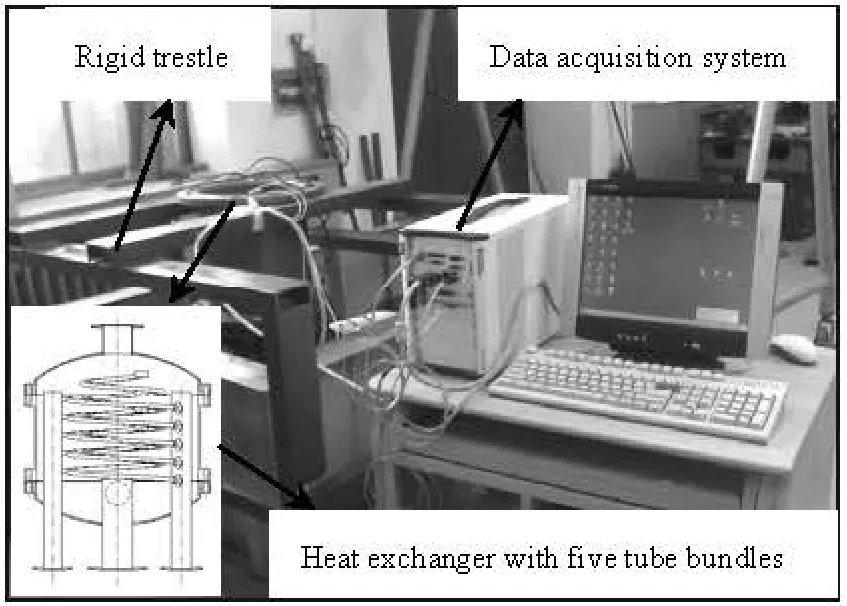
Fig.1 Structure of the experiment table
1. Experimental test of tube vibration
1.1Experiment process and parameters
Figure 1 shows the experiment table. The heat exchanger is supported by a rigid trestle of large size and weight in order to insulate the interference signal of the pump. The three-phase oil-filled submersible pump (QY160-6-4C) is used in the water circulation system, with a rated flow of 160 m3/h, and the synchronous speed is 3 000 rpm. The rotational speed of the pump is controlled by an inverter, so the shell side fluid flow speed can be precisely adjusted. The fluid flow speed during the experiment is shown in Table 1.
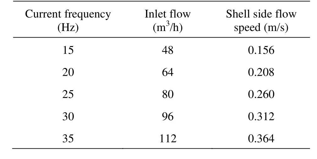
Table 1 The fluid flow parameter
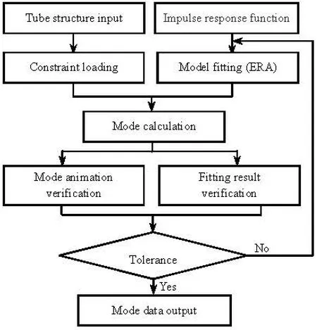
Fig.2 Flow chart of the experimental test
The heat exchanger in the experiment contains five conical spiral tube bundles of 0.93 m in height and 0.63 m in flange diameter. The testing points are uniformly arranged on the tube bundle, with a uniform central angle of 18o. Five acceleration sensors (PCBW352C65) of ICP signals are fixed on the testing points, and the signals of the five sensors are used as the response signals. Another one sensor is fixed on the free end of the tube bundle, the 24th testing point,whose signal is used as the exciting signal. During the experiment, the exciting sensor is fixed on the free end of the tube, while the five response sensors were successively fixed on the fifty five testing points, which means five test points at a time and totally eleven times. The NI-PXI-1042Q is used as the data acquisition system and the vibration signals picked in the experiment are fitted with the Coin-DASP-MAS mode analysis software.
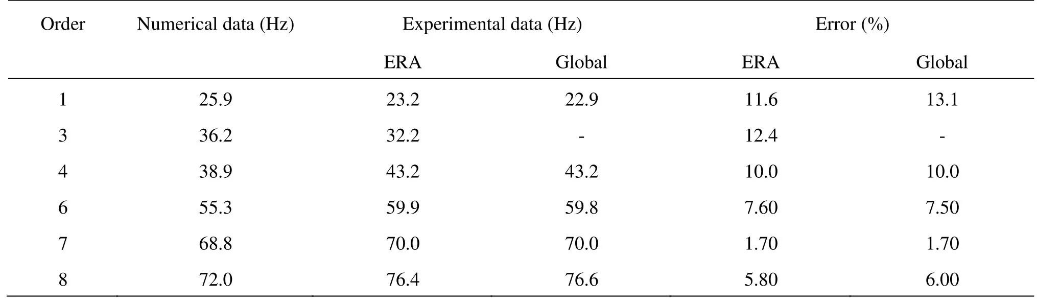
Table 2 The natural frequencies of conical spiral tube bundle in longitudinal vibration
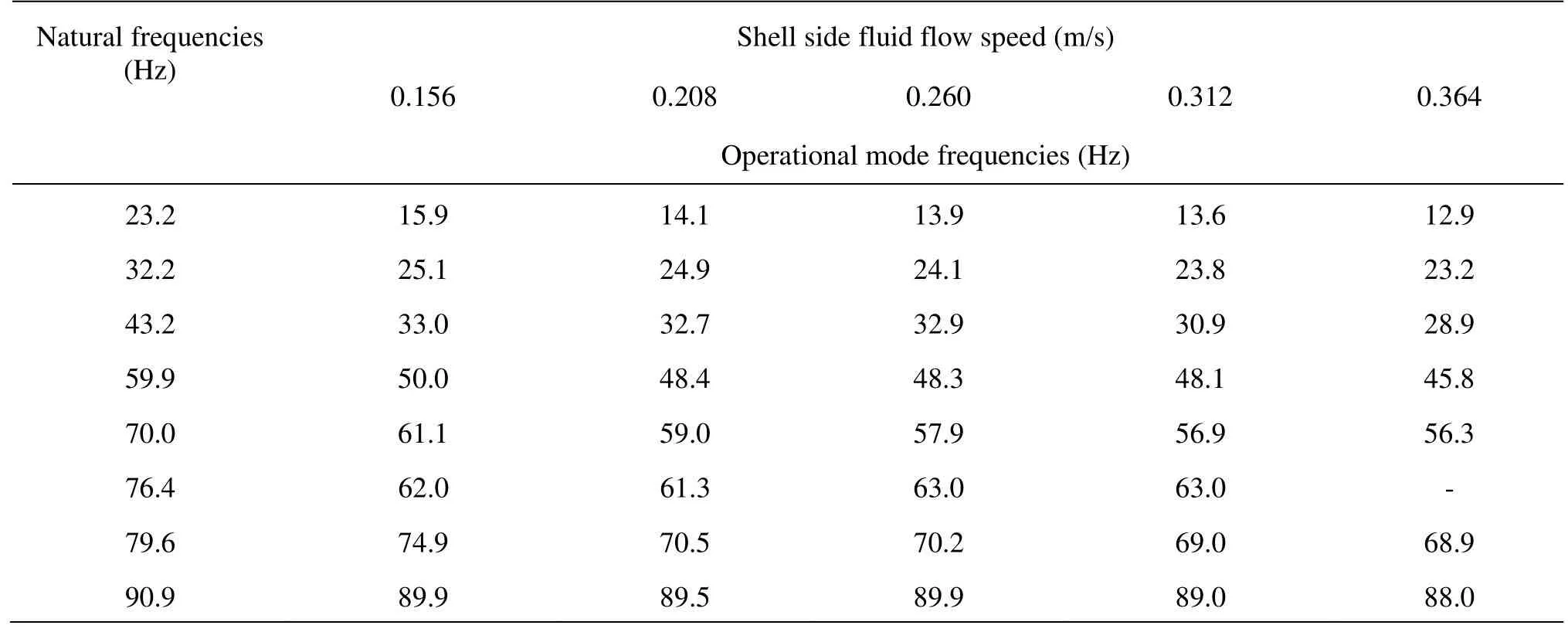
Table 3 The operational mode frequencies of conical spiral tube bundle
The experiment process for the operational mode is different from that for the natural mode[13,14],due to the failure of the hammering method in our working conditions. During the operational mode test, the fluid force is the real exciting signal, and the vibrating signal of the 24th testing point is used as the exciting signal, the other signals of the testing points are used the response signals. The experiment chart of the operational mode is shown in Fig.2. The coordinates of the testing points were measured and then the constraints were loaded. The vibration signals of the testing points were captured and fitted via the eigensystem realization algorithm (the ERA method) in the time domain. Subsequently, the vibration modes were verified both by the Mode Important Index (MII) and the convergent times of the fitting results.
1.2Verification of the experimental data
The verification of the testing data is made both by experiment and numerical simulation on the natural mode frequency of the conical spiral tube bundle in the longitudinal vibration. The hammering method was employed in the experiment. The response signals were analyzed both in the frequency domain and the time domain, with the Global method and the ERA method, respectively. The MII was used to identify the vibration mode. In the numerical simulation, a model was built of the same size as the experiment object. The numerical model was divided into elements of Pipe16, the free end of the tube was simplified as a rigid body with lumped mass. The Block-Lanczos method was employed in the numerical simulation.
The natural mode frequencies of the conical spiral tube bundle in the longitudinal vibration are listed in Table 2. It can be seen that the deviation between the testing data and the numerical data is small. The biggest difference is about 13.1%.
2. Results and discussions
2.1The operational mode frequency
The operational mode frequencies of the conical spiral tube bundle are listed in Table 3. The operational mode frequencies of the conical spiral tube bundle are all less than the related natural frequencies. The 1st order frequency is decreased by about 30% for the shell side fluid flow speed of 0.156 m/s. With the increase of the shell side fluid flow speed, the frequencies of the tube bundle are further decreased, while the reduced extent for the higher order frequencies are much smaller than for the lower order frequencies.
As mentioned above, the mode frequencies of the elastic tube bundle are decreased about 10% to 15% in still water. With the tube side fluid flow, the basic frequencies of the tube bundle are reduced slightly for the flow speed in the range of 0.1 m/s to 0.3 m/s. From Table 3 it can be seen that, the shell side fluid flow has a significant influence on the vibration characteristics of elastic tube bundles. Therefore, the further investigation of the fluid-structure interaction for the shell side fluid flow is highly desirable in the design of elastic tube bundle heat exchangers.
2.2The vibration frequency
The actual vibration frequency of the conical spiral tube bundle under the working condition can be obtained via the Fast Fourier Transform (FFT). The vibration frequency at the tube free end, namely the 24th testing point, is discussed based on the experimental data. To reduce the random error, the sampling time of thirty seconds is taken and at least four samples are considered in each case.
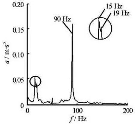
Fig.3 Tube vibrating frequency under working conditions (flow speed of 0.156 m/s)
The actual vibration frequency of the conical spiral tube bundle can be seen in Fig.3 for the shell side fluid flow speed of 0.156 m/s. It can be seen that the spectrum contains three frequencies of 15 Hz, 19 Hz and 90 Hz, in which the acceleration signals of 15 Hz and 90 Hz are relatively larger in amplitude. During the experiment, the heat exchanger is supported via a large trestle, and the pump is hanging from the foundation. Therefore, the interference of the pump vibration and the tank vibration is slight. The main interference source is the vibration of the pump impeller via the shell side fluid flow. From Table 2 it can seen that for the shell side fluid flow speed of 0.156 m/s, the natural frequency is 15 Hz, and most of the interference may come from the octave interference of 15 Hz, such as 45 Hz and 90 Hz. Based on the above analysis, the real vibration frequency of the conical spiral tube bundle excited by the shell side fluid flow is 19 Hz, and the 15 Hz and 90Hz are all interference frequencies.
Another issue in Fig.3 is that the acceleration signals of the interference are even larger in amplitude than that of the vibration frequency excited by the fluid flow. It can be explained by the operational modes in Table 3. The operational mode frequencies include 15.9 Hz and 89.9 Hz, and the interference frequencies are close to them, thus their responses are increased.
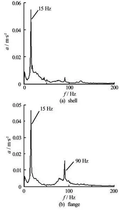
Fig.4 Vibrating frequency of heat exchanger components (flow speed of 0.156 m/s)
In order to confirm the deduction, the vibration frequencies of the heat exchanger shell, the upper flange and the lower flange are tested. In ideal experimental conditions, the shell and flange of the heat exchanger are all stationary. The spectrums show that the frequencies of the heat exchanger shell and flange are 15 Hz and 90 Hz, which are all interference signals. Moreover, the amplitude in Fig.4 are relatively small, due to the much larger size and weight of theshell and flange, compared to the conical spiral tube bundle.
A further verification of the tube bundle vibration is done for the shell side fluid flow speed of 0.208 m/s, as listed in Table 1. It can be seen that in the spectrum the two frequencies of 19 Hz and 20 Hz are included, in which 20 Hz is the interference signal. Meanwhile, there exist other small interferences such as those of the frequencies of 60 Hz and 80Hz, which are all the octave interferences of 20 Hz.
Fig.5 Tube actual frequency (flow speed 0.260 m/s)
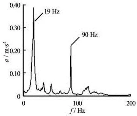
Fig.6 Tube actual frequency (flow speed 0.312 m/s)
Similar conclusions can be reached for the shell side fluid flow speeds of 0.260 m/s and 0.312 m/s, as shown in Fig.5 and Fig.6. Within the scope of the experiment parameters, the actual vibration frequency of the conical spiral tube bundle is about 19 Hz (18 Hz for the shell side flow speed of 0.364 m/s). Under the condition of the shell side fluid flow, the first order operational mode frequency of the tube bundle is between 15.9 Hz and 12.9 Hz, the second order frequency is from 25.1 Hz to 23.2 Hz, and the actual vibration frequency of the tube is about 19 Hz, which indicates that the tube vibration is between its 1st and 2nd operational modes. Similar conclusion can be reached with another experiment of the planar elastic tube bundle.
2.3The vibration amplitudes
The vibration amplitude can be obtained via the integration of vibration signals. The vibration amplitude of the conical spiral tube bundle at the 24th testing point is investigated under the condition of the shell side flow speed between 0.156 m/s and 0.364 m/s. It can be seen that for the shell side flow speed less than 0.260 m/s, the vibration amplitude of the conical spiral tube bundle increases slightly. When the fluid flow speed is close to 0.3 m/s, the vibration amplitude increases suddenly. From Fig.7 it can be seen that the amplitude at the 24th testing point continuously increases with the increase of the shell side fluid flow speed. The amplitude at the 1st and the 55th testing points are relatively small, because the two points are connected with the inlet and outlet risers in the heat exchanger.
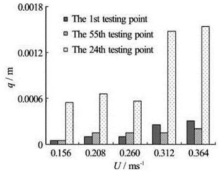
Fig.7 Vibration amplitude of conical spiral tube bundle
The influence of interference signals on the vibration amplitude of the conical spiral tube bundle is also analyzed, as listed in Table 4. Compared to the amplitude at the tube free end, the vibration amplitude of the shell and the flange are relatively small.
2.4Tube vibration parameters and heat transfer enha
ncement
Most investigations show that the tube vibration plays a positive role in the heat transfer enhancement only in a certain parameter range, namely, the effective parameter range. The conclusions in many references show that in the effective parameter range, the heat transfer coefficient is about 13% to 311% improved[11,15,16]. The experiments in this paper indicate that the vibration parameters of the conical spiral tube bundle are in the range of effective parameters, which means that the flow-induced vibration will play a positive role in the heat transfer enhancement for heat exchangers with conical spiral tube bundles[17].
3. Conclusions
The shell side flow-induced vibration of the conical spiral tube bundle is experimentally investigated in this paper. The experiment table was built and the operational modes, the vibration parameters of the tube bundle were comprehensively investigated. Within the parameter range of this experiment, the conclusions are as follow:
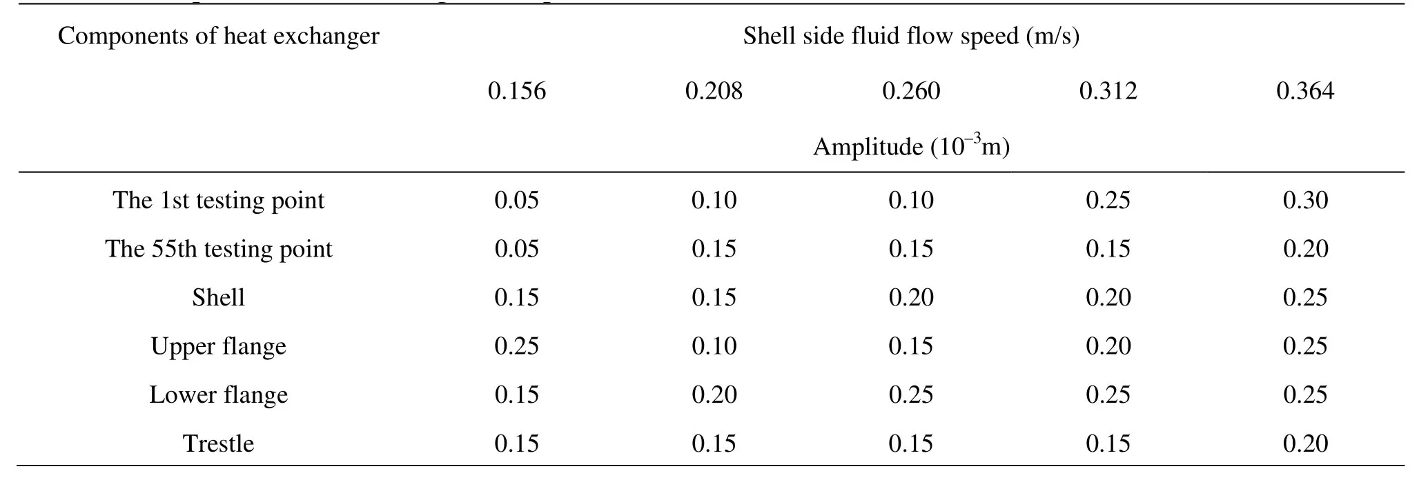
Table 4 The amplitude of heat exchanger’s components
(1) The operating mode frequencies of the conical spiral tube decrease as the shell-side fluid flow velocity increases, especially for the first order frequency. For the shell-side flow speed of 0.156 m/s, the first order frequency of the conical spiral tube bundle is decreased by about 30%. Compared to the first order frequency, the decreasing extent for high order frequencies is slighter.
(2) The vibration frequency of the conical spiral tube bundle in the shell-side fluid flow is about 19 Hz. The first operating mode frequency of the conical spiral tube bundle is from 15.9 Hz to 12.9 Hz, the second operating mode frequency of the conical spiral tube bundle is from 25.1 Hz to 23.2 Hz. It can be seen that the vibration frequency of the conical spiral tube is between those of the 1st and the 2nd operating modes.
(3) Under the condition of the shell-side fluid flow speed of 0.126 m/s-0.26 m/s, the free end vibration amplitude of the conical spiral tube bundle increases slowly. The vibration amplitude of the conical spiral tube bundle increases greatly when the shellside fluid flow speed exceeds 0.3m/s. Namely, the vibration amplitude of the tube bundle increases greatly when the shell side fluid flow velocity exceeds a critical value.
(4) The flow-induced vibration parameters of the conical spiral tube bundle are in the range of effective parameters, which means the flow-induced vibration will play a positive role in the heat transfer enhancement for heat exchangers with conical spiral tube bundles.
[1] CHENG L., LUAN T. and DU W. et al. Heat transfer enhancement by flow-induced vibration in heat exchangers[J]. International Journal of Heat and Mass Transfer, 2009, 52(3-4): 1053-1057.
[2] CHENG Lin. Principle and application of elastic tube heat exchanger[M]. Beijing, China: Science Press, 2001(in Chinese).
[3] GE M. R., YAN K. and GE P. Q. et al. Study on the conical spiral tube bundle heat exchangers with pulsation flow generator structure[J]. Applied Mechanics and Materials, 2012, 143-144: 698-702.
[4] GE M. R., YAN K. and GE P. Q. et al. Vibration characteristics of multiple conical spiral tube bundles in heat exchangers[J]. Advanced Materials Research, 2012, 403-408: 722-726.
[5] NAPHON P., NUCHJAPO M. and KURUJAREON J. Tube side heat transfer coefficient and friction factor characteristics of horizontal tubes with helical rib[J]. Energy Conversion and Management, 2006, 47(18-19): 3031-3044.
[6] LIU Rui-lan, SU Guang-hui and XIAO Gang et al. Analysis of the dynamic characteristics of helical tube[J]. Atomic Energy Science and Technology, 2000, 34(5): 399-405(in Chinese).
[7] YAN Ke, GE Pei-qi and BI Wen-bo et al. Vibration characteristics of fluid-structure interaction of conical spiral tube bundle with FEM[J]. Journal of Hydrodynamics, 2010, 22(1): 121-128.
[8] GUILMINEAU E., QUEUTEY P. A numerical simulation of vortex shedding from an oscillating circular cylinder[J]. Journal of Fluids and Structures, 2002, 16(6): 773-794.
[9] SARPKAYA T. A critical review of the intrinsic nature of vortex-induced vibrations[J]. Journal of Fluids and Structures, 2004, 19(4): 389-447.
[10] ZHENG Ji-zhou. Dynamic characteristics of components of elastic tube bundle heat exchanger[D]. Doctoral Thesis, Jinan, China: Shandong University, 2007(in Chinese).
[11] JIANG Bo. Analysis on mechanism of heat transfer enhancement by vibration and experimental research on a new type of heat transfer component[D]. Doctoral Thesis, Jinan, China: Shandong University, 2010(in Chinese).
[12] YAN Ke, GE Pei-qi and SU Yan-cai et al. Mathematical analysis on transverse vibration of conical spiral tube bundle with external fluid flow[J]. Journal of Hydrodynamics, 2010, 22(6): 816-822.
[13] KHATIBI M. M., ASHORY M. R. and MALEKJAFARIAN A. Mass-stiffness change method for scaling of operational mode shapes[J]. Mechanical Systems and Signal Processing, 2012, 26: 34-59.
[14] CARA F. J., CARPIO J. and JUAN J. et al. An approach to operational modal analysis using the expectation maximization algorithm[J]. Mechanical Systems and Signal Processing, 2012, 31: 109-129.
[15] JIANG Bo, TIAN Mao-cheng and LENG Xue-li et al. Numerical simulation of flow and heat transfer characteristics outside a periodically vibrating tube[J]. Journal of Hydrodynamics, 2008, 20(5): 629-636.
[16] BRUNO S. C., GUSTAVO R. S. and JULIO R. M. Computational simulation of the flow-induced vibration of a circular cylinder subjected to wake interference[J]. Journal of Fluids and Structures, 2013, 41: 99-108.
[17] XU Wan-hai, YU Jian-xing and DU Jie et al. Prediction of streamwise flow-induced vibration of a circular cylinder in the first instability range[J]. China Ocean Engineering, 2012, 26(4): 555-564.
10.1016/S1001-6058(13)60414-X
* Project supported by the China Postdoctoral Science Foundation (Grant No. 2012M521768), the National Basic Research Program of China (973 Program, Grant No. 2011CB706606).
Biography: YAN Ke (1984-), Male, Ph. D., Lecturer
杂志排行

水动力学研究与进展 B辑的其它文章
- A one-dimensional polynomial chaos method in CFD–Based uncertainty quantification for ship hydrodynamic performance*
- Numerical analysis of cavitation within slanted axial-flow pump*
- Numerical simulation of hydro-elastic problems with smoothed particle hydrodynamics method*
- Analytic solutions of the interstitial fluid flow models*
- A streamline approach for identification of the flowing and stagnant zones for five-spot well patterns in low permeability reservoirs*
- Theoretical analysis and experimental study of oxygen transfer under regular and non-breaking waves*