The influence of the flow rate on periodic flow unsteadiness behaviors in a sewage centrifugal pump*
2013-06-01PEIJi裴吉YUANShouqi袁寿其YUANJianping袁建平WANGWenjie王文杰
PEI Ji (裴吉), YUAN Shou-qi (袁寿其), YUAN Jian-ping (袁建平), WANG Wen-jie (王文杰)
Research Center of Fluid Machinery Engineering and Technology, Jiangsu University, Zhenjiang 212013, China, E-mail: peiji1984@163.com
(Received September 15, 2012, Revised March 11, 2013)
The influence of the flow rate on periodic flow unsteadiness behaviors in a sewage centrifugal pump*
PEI Ji (裴吉), YUAN Shou-qi (袁寿其), YUAN Jian-ping (袁建平), WANG Wen-jie (王文杰)
Research Center of Fluid Machinery Engineering and Technology, Jiangsu University, Zhenjiang 212013, China, E-mail: peiji1984@163.com
(Received September 15, 2012, Revised March 11, 2013)
To design a single-blade pump with a good performance in a wide operational range and to increase the pump reliability in the multi-conditional hydraulic design process, an understanding of the unsteady flow behaviors as related with the flow rate is very important. However, the traditional design often considers only a single design condition, and the unsteady flow behaviors have not been well studied for single-blade pumps under different conditions. A comparison analysis of the flow unsteadiness behaviors at different flow rates within the whole flow passage of the pump is carried out in this paper by solving the three-dimensional unsteady Reynolds-averaged Navier-Stokes equations with the Shear Stress Transport (SST) turbulence model. A definition of the unsteadiness in the pump is made and applied to analyze the unsteady intensity distributions, and the flow rate effect on the complex unsteady flow in the pump is studied quantitatively while the flow mechanism is also analyzed. The CFD results are validated by experimental data collected at the laboratory. It is shown that a significant flow rate effect on the time-averaged unsteadiness and the turbulence intensity distribution can be observed in both rotor and stator domains including the side chamber. The findings would be useful to reduce the flow unsteadiness and to increase the pump reliability under multi-conditions.
flow rate effect, flow unsteadiness, turbulence intensity, sewage centrifugal pump, multi-conditions
Introduction
Due to the Rtor-Stator Interaction (RSI), the flow around the impeller of a single-blade centrifugal pump produces a strongly asymmetrical unsteady effect at both Best Efficiency Point (BEP) and other operating points. This phenomenon, therefore, leads to a periodical hydrodynamic force acting on the impeller surface and results in strong rotor vibrations[1]. The RSI effect in centrifugal pumps was investigated numerically and experimentally. Feng et al.[2-6]investigated the RSI effect in a radial diffuser pump by a comparison among CFD calculated results, PIV and LDV measurement results, and indicated that the RSI has two kinds of effects on centrifugal pumps with diffusers. The first is the downstream effect of the impeller on the stator flow, which is characterized by unsteady effects due to the highly distorted relative impeller flow field and impeller wakes, the second is the upstream effect of the stator on the impeller flow, which causes unsteady pressures on the relative flow and velocity fluctuations.
Studies of single-blade pumps were carried out by using numerical and experimental methods. Benra et al.[7]presented an investigation of the periodic unsteady flow in a single-blade pump by using the CFD simulation and PIV measurement methods. The results of transient numerical simulations compare very well with the velocity measurements, but this is only true when all flow details are included into the numerical calculation. Pei et al.[8]investigated the flow-induced vibrations of the single-blade sewage water pump impeller under off-design conditions using numerical and experimental methods. Different strategies of the partitioned fluid-structure interaction simulation for a single-blade pump impeller were studied, and results obtained by one-way and two-way coupling strategies were compared and analyzed[9]. Pei et al.[10]evaluated the transient pressure variation in a single-blade pumpunder multi-conditions by defining the standard deviation of the pressure fluctuation in a revolution period. De Souza et al.[11]focused on the optimization of single-blade impeller hydraulics from the perspective of both the performance and the solid handling ability by numerical simulations. Yasuyuka et al.[12]proposed a method of designing a single-blade centrifugal impeller for which the passed particle size is specified based on CFD analysis. De Souza et al.[13]addressed the volute design as applied to single-blade impeller pumps. Keays and Meskell[14]carried out a numerical study of a single-vanned waste-water pump using the commercial CFD software.
However, the unsteady flow field and the turbulence behavior caused by the RSI should be analyzed for single-blade pumps under different operational conditions, because the pump is not often running only at the design flow rate. The comparison analysis of flow unsteadiness behaviors under different running conditions is important to gain an insight of the complex flow in the pump and to design a singleblade pump with better performance for a wide range of reliable operations.
This paper focuses on a comparison analysis of flow unsteadiness behaviors under different flow rates for a single-blade centrifugal pump in the whole flow passage. The periodic flow unsteadiness results under different conditions are quantitatively compared by defining the unsteady intensity and the turbulence intensity in both impeller and volute, which can improve the understanding of the impeller-volute interaction in single-blade pumps as related with the flow rate.
1. Computational model and method
A commercial single-stage single-suction horizontal centrifugal pump with a single-blade impeller is selected as the calculation model. An overview of the pump rotor and the test pump is shown in Fig.1. The design parameters of the pump are listed in Table 1.
Three-dimensional, unsteady Reynolds-averaged Navier-Stokes equations are solved using the Shear Stress Transport (SST) turbulence model. The structured grids for computational domains are generated using the grid generation tool ICEM-CFD 12.1 and the grid details are shown in Fig.2 with a total number of grid nodes of 2 182 132 for both rotating and stationary domains. The independence of the solutions from the number of grid nodes is checked by simulating the flow field with different numbers of grid nodes. The maximum non-dimensional wall distancey+<80 is obtained in the complete flow field. Both the hub and shroud side chambers between the impeller and the pump casing are also included in the grid to take the leakage flow effect into account, as shown in Fig.3.
The discretization in space is of second-order accuracy, and the second-order backward Euler scheme is chosen for the time discretization. The interface between the impeller and the casing is set to the “transient rotor-stator” to capture the transient rotor-stator interaction in the flow, because the relative position between the impeller and the casing changes in each time step with this kind of interface. Two different coordinate systems are utilized for the rotatory and stationary domains, respectively. The inlet boundary condition is set to the total pressure in the stationary frame while the outlet condition is set to the mass flow rate, and all specific values are obtained from laboratory tests. The smooth wall condition is used for the near wall function. The chosen time step Δtfor the transient simulation is 3.47225×10⁻⁴s for the nominal rotating speed, corresponding to a changed angle of 3o, therefore, 120 transient results are included for one impeller revolution calculation. Within each time step, 10 iterations may be performed and the iteration stops when the maximum residual is less than 10-3. The convergence criterion for the transient problem is that the result reaches its stable periodicity state, 9 revolutions of the impeller for each operational condition in this case are included. To obtain the stable numerical results, an initial value distribution of the flow parameters as exact as possible is required. To provide this starting solution, a steady calculation with the frozen rotor strategy is made.
2. Flow unsteadiness definition
The unsteady intensity and the turbulence intensity, as the indices of the flow unsteadiness, in bothimpeller and volute domains, are defined according to Ref.[2].
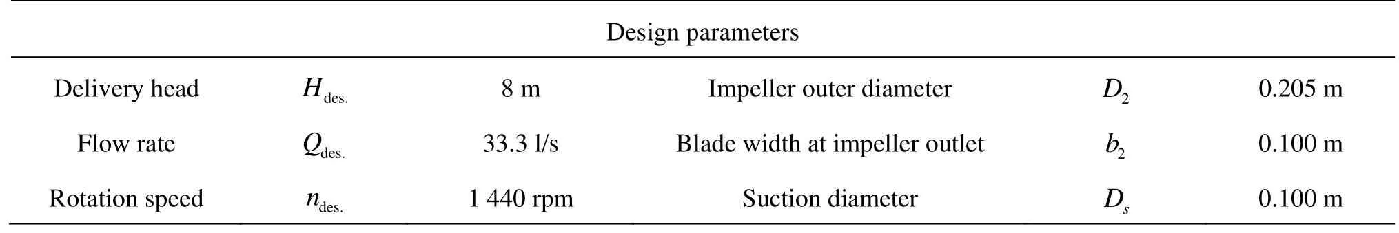
Table 1 Parameters of the pump
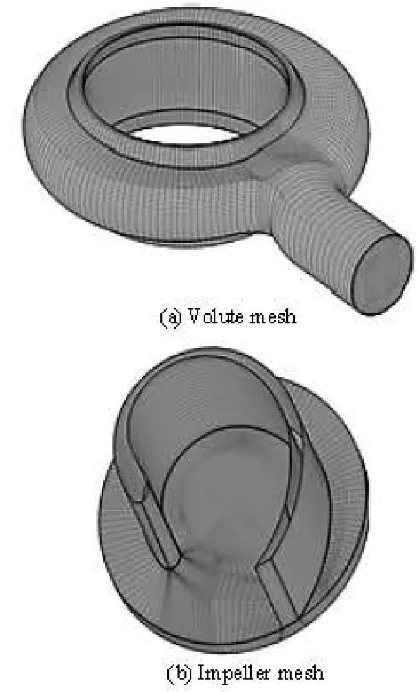
Fig.2 Grid details
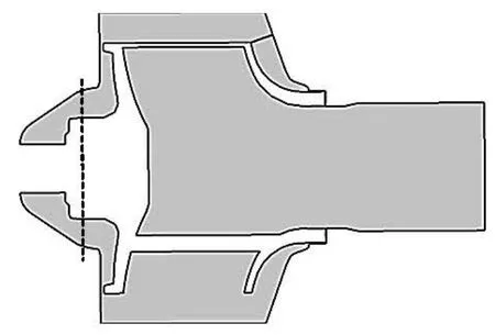
Fig.3 Rotor fluid domain view in a meridional plane
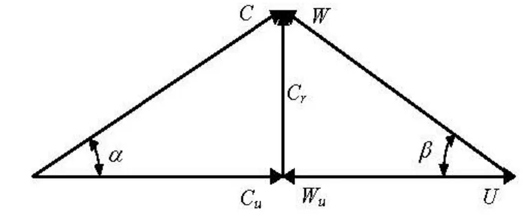
Fig.4 Velocity triangle
Due to the CFD calculation based on URANS equations, the velocity component inside the pump consists of two parts: a time-average component and a periodic component, therefore, the random fluctuating velocity components associated with the unsteady phenomena which are not correlated with the impeller frequency are not considered. Each relative velocity component in the rotating domain and each absolute velocity component in the volute region can be expressed as follows:
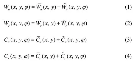
whereWurepresents the relative circumferential velocity component,Wrrepresents the relative radial velocity component,CuandCrrepresent the absolute circumferential velocity component and the absolute radial velocity, respectively, and they can be calculated in cylindrical systems according to the azimuth angle from the absolute velocity components inx-axis andy-axis directions. Here the meridional componentCmis assumed to be equal to the radial componentCr.?,?,?and?represent the time-averaged components, obtained from all results in one impeller revolution period.?,?,?and?represent the periodic components caused by different relative impeller circumferential positions to the volute tongue. The velocity components can be shown in a typical velocity triangle of centrifugal pumps, as in Fig.4. The relative velocity components can be obtained from Eqs.(5) and (6)
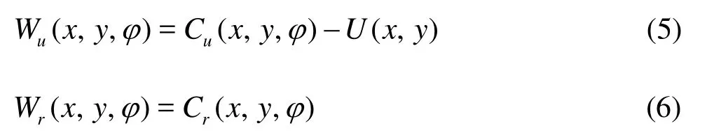
wheretφis the impeller position at the instant timet, andTis the period of the pump rotation.
The time-averaged velocity components can be calculated from Eqs.(7) through (10)
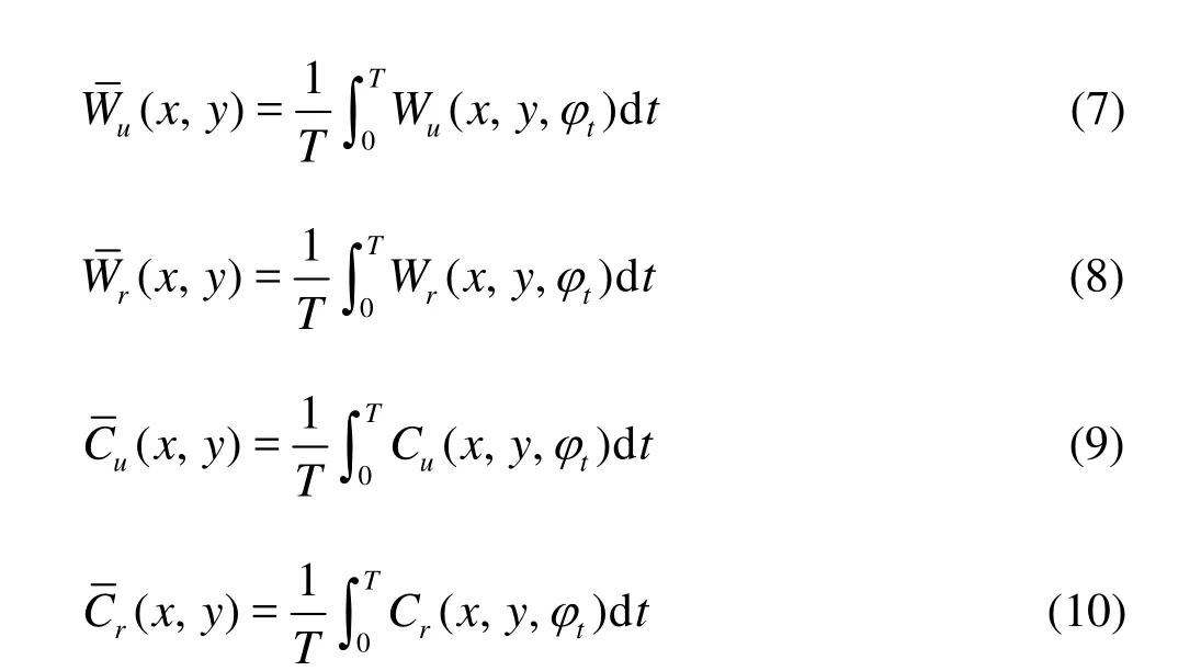
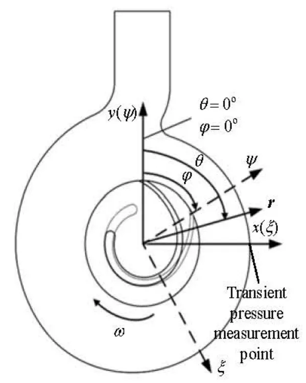
Fig.5 Definition of angle parameters and monitor points
In order to examine quantitatively the unsteadiness of the impeller relative flow, the impeller unsteady intensityIuis defined in Eq.(11).Iuis calculated by the root mean square of two periodic components normalized by the impeller tip speedU2. And the time-averaged unsteady intensity?is calculated according to Eq.(12) considering results of 120 time steps in one impeller revolution, and the examined points in the rotor region are in the rotating frame of reference. The stator unsteady intensitySuis defined by the root mean square of two absolute periodic velocity components in Eq.(13), and the time-averaged unsteady intensity?is calculated according to Eq.(14).
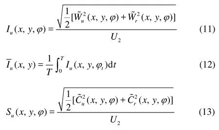
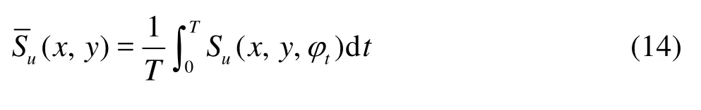
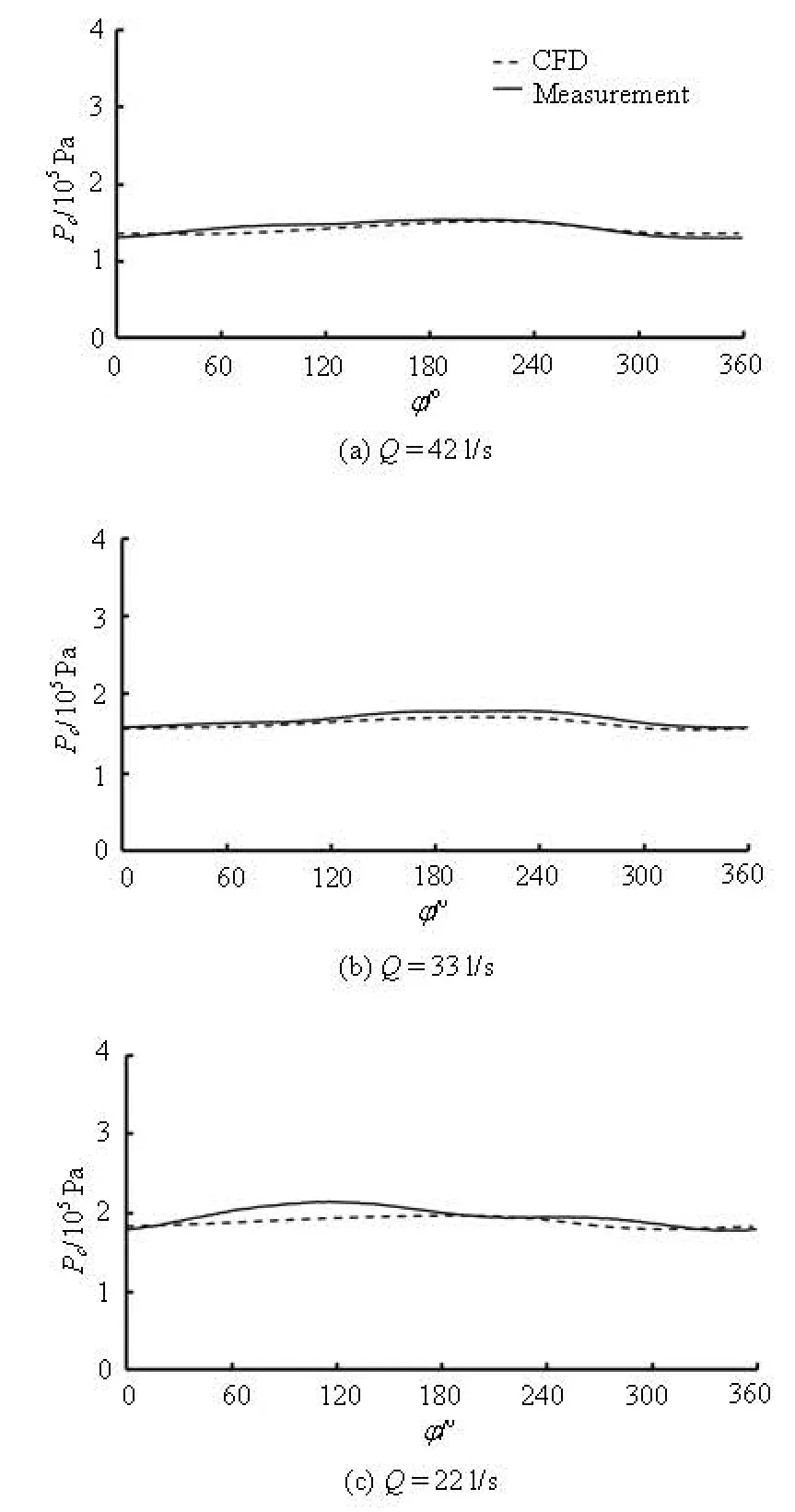
Fig.6 The comparison of experimental and numerical pressure fluctuation results on the casing
Fig.7 Relative velocity vector distribution at midspan forQ= 33l/s,φ=0o
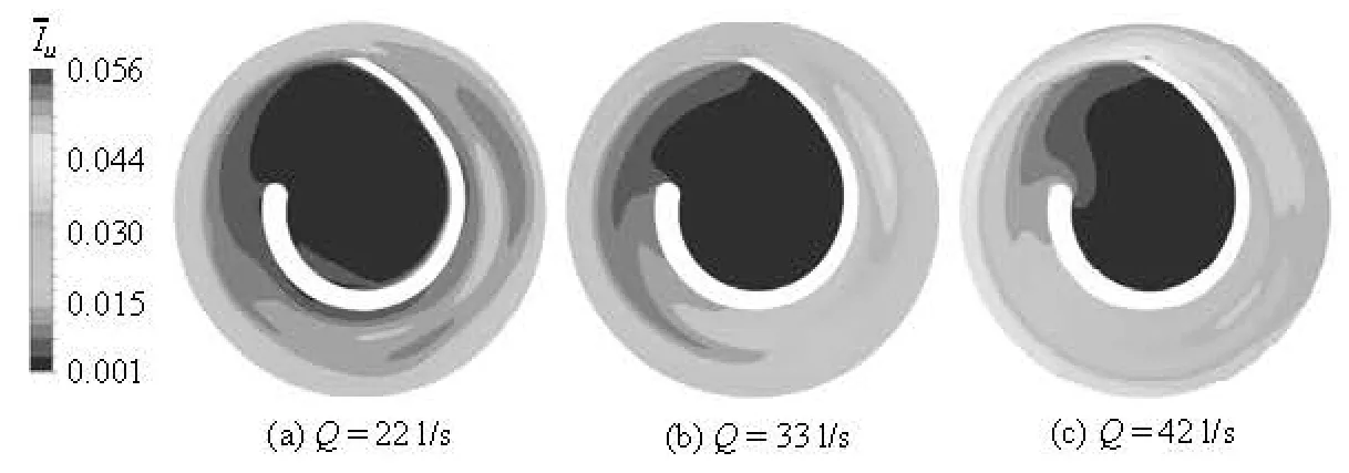
Fig.8 Comparison of multi-condition results of time-averaged rotor unsteadiness at midspan
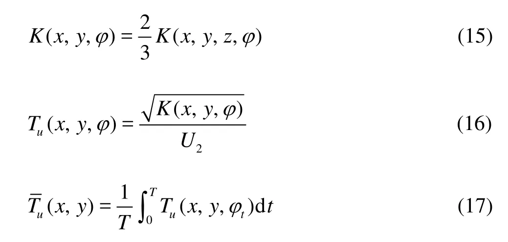
The turbulence intensityTuis defined in Eqs.(15) and (16) based on the turbulence kinetic energyK(x,y,φ), and the isotropic assumption is used to calculate the turbulence kinetic energy with consideration of two components. The time-averaged turbulence intensity?in one period is calculated according to Eq.(17)
3. Results of comparison
For analyzing the flow unsteadiness under various conditions, two coordinate systems are defined, the stationary coordinate frame marked asx,yand the rotating coordinate frame marked asψ,ξ, as shown in Fig.5. The rotating position of the impeller is indicated by defining the rotating angleφbetween the positive axisψof the rotating coordinate frame and the positiveyaxis of the stationary coordinate frame in the clockwise direction, andφ=0omeans that the trailing edge of the impeller is at the top position. The angle of the circumferential position in the stationary coordinate is defined asθ, andθ=0owhenx=0 m andy>0 m. The circumferential position angleθincreases in the clockwise direction in thex,ycoordinate system, as shown in Fig.5.
Experimental data are collected for the model pump in the laboratory of the Institute of Turbomachinery at University of Duisburg-Essen, Germany, to verify the accuracy of the calculation. The transient pressure results at the transient pressure measurement point, shown in Fig.5, on the casing by both CFD and experimental methods are qualitatively compared under multi-conditions, as shown in Fig.6, and the numerical results are validated.
Figure 7 shows the relative velocity vector distribution at the midspan under the design condition (Q=33l/s) whenφ=0ofrom an unsteady simulation result, and the legend represents the velocity scale in the calculation domain. The stable flow patterns can be observed in the volute domain, and the velocity is relatively small. Therefore, the kinetic energy of the flow is transformed into the pressure energy very well in this volute under the design condition. Because the circumferential velocity of the domain is zero, the relative velocity is equal to the absolute velocity in the volute. In the rotor domain, a significantly unbalanced velocity distribution can be observed because of the asymmetrical blade shape. A relatively low velocity appears near the blade pressure side and the impeller eye position. A relatively large velocity appears near the blade suction side and at the circumferential area of the blade outlet, and the maximum velocity can be found at the outermost position of the impeller. The almost same phenomenon can be observed at each examined flow rate. However, the relative velocity distribution results are obtained at a specified time, the velocity field is also fluctuating with time which is called the unsteadiness in this paper, and this phenomenon cannot be shown in a single figure. To study the intensity distribution of the flow fluctuation and the mechanism of the unsteadiness phenomenon, a number of pictures of flow distributions at each time point or at a number of monitor points at each position containing the time-history results should be obtained to describe the phenomenon in the whole flow passage, which is not efficient and even possible. Therefore, applying the time-averaged unsteadiness intensity coefficients defined in this paper to analyze the unsteadiness mechanism in the pump is a better choice as with the coefficients one can use a single value at each location to describe the unsteadiness intensity with consideration of the whole time-history fluctuating results for an impeller revolution.
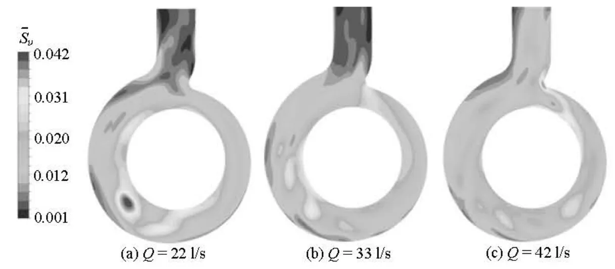
Fig.9 Comparison of multi-condition results of time-averaged volute unsteadiness at midspan
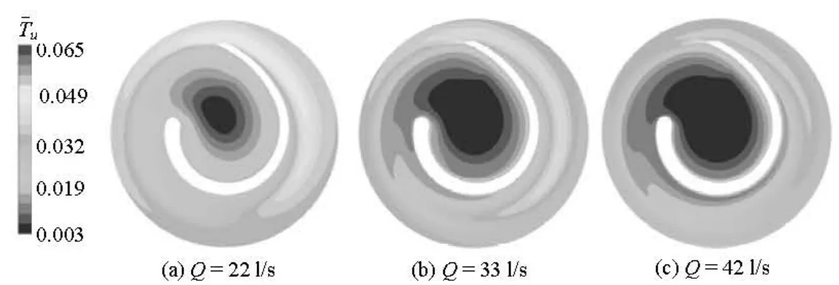
Fig.10 Comparison of multi-condition results of time-averaged turbulence intensity in the impeller at midspan
Figure 8 shows the comparison of multi-condition results of the time-averaged rotor unsteadiness coefficients at the midspan. For each flow rate, relatively large values can be observed near the impeller outlet and near the blade pressure side, and the values increase when the flow rate increases. At three examined flow rates, the maximumIuresult can be observed at the trailing edge close to the pressure side of the blade forQ=42 l/s. Because under a large flow rate condition, more power is required from the blade by the fluid while more kinetic energy is transferred to the fluid, and the wake flow with a relatively high velocity near the blade trailing edge will have a stronger interaction downstream with the volute tongue, and a strong velocity fluctuation will appear. At a small flow rate, less power is required from the blade, and a weak interaction between the fluids in the rotor and in the stator is observed, which means a weak periodic velocity fluctuation.
Figure 10 shows the comparison of multi-condition results of the time-averaged turbulence intensity
in the impeller at the midspan.Turepresents the flow random fluctuation intensity with consideration of the cumulative effect of the flow results in an impeller revolution. At each flow rate, relatively large values can be observed in the area near the impeller outlet and in the area near the blade pressure side, and the values increase when the flow rate decreases, because at a large flow rate, much more energy of the rotating blade is transferred to the fluid in a relatively strong periodic flow by the RSI effect, and less energy of fluid is spent in the turbulent random fluctuation. At a small flow rate, the periodic flow fluctuation is relatively weak with an unexpected impeller-volute matching as shown in Fig.8 while a chaotic flow with more unstable vortexes will be produced, therefore, more residual energy will be spent in the turbulent velocity random fluctuation. Under the design condition, relatively moderate distribution results are obtained.
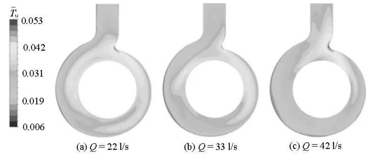
Fig.11 Comparison of multi-condition results of time-averaged turbulence intensity in the volute at midspan
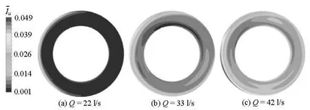
Fig.12 Comparison of multi-condition results of time-averaged unsteadiness on the cross section of side chambers
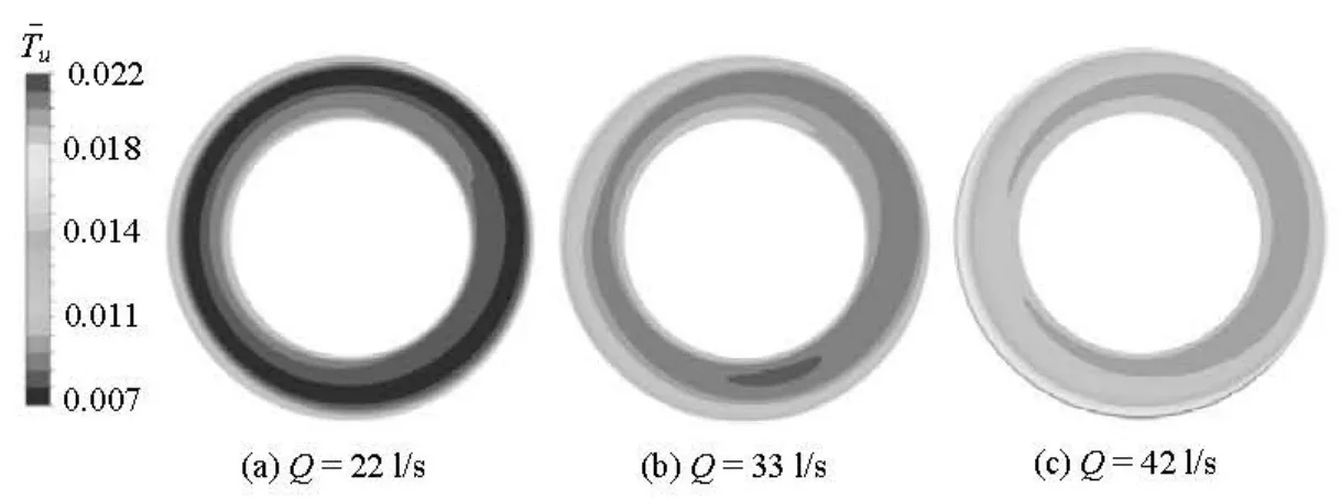
Fig.13 Comparison of multi-condition results of time-averaged turbulence intensity on the cross section of side chambers
Figure 11 shows the comparison of multi-condition results of time-averaged turbulence intensity in the volute at the midspan. A high turbulent flow can be seen near the tongue for an impeller revolution under each condition, and the area is bigger under the off-design conditions. The reason is that, at large and small flow rates, the flow in the volute is not smooth, the volute tongue will have a great influence on the flow velocity and much energy losses are caused. Therefore, the flow in the area becomes quite chaotic and varies strongly with time.
Figure 12 shows the comparison of multi-condition results of?on the cross section of the side chambers, and the position of the cross section is shown in Fig.3. The values increase with the increase of the flow rate, because the source of the periodic flow phenomenon is in the impeller and volute channels, the flow in the side chamber is affected by the periodical unsteady flow in the main channel. The periodic unsteadiness intensity increases with the increase of the flow rate, as shown in Fig.8, therefore, the influence on the side chamber flow becomes significant with the increase of the flow rate.
Figure 13 shows the comparison of multi-condition results of?on the cross section of the side chambers, and the values increase with the increase of the flow rate. The reason is that, at a large flow rate, a higher flow velocity in the pump channel is obtained, and more energy can be transferred to the side chamber fluid. Therefore, a part of energy can make the flow in the side chamber chaotic and make the flow relatively more turbulent in the impeller revolution. Although a relatively large?can be found in the impeller channel at a small flow rate, as shown in Fig.10, the impeller flow can be found to have a small influence on the side chamber flow under this condition.
4. Conclusions
To consider the flow rate effect, the behavior of the unsteady flow in the pump is analyzed from a new angle of view by defining the flow unsteadiness coe-fficients for a single-blade centrifugal pump within the whole flow passage. The CFD results are validated by experimental data collected at the laboratory. The unsteadiness distribution results under multi-conditions are studied while the flow mechanism behind that is analyzed. The following conclusions are drawn:
沟渠生态修复区主要位于河道、灌渠、排涝渠两侧及坑塘周边地带,是维系平原生态的重要廊道。该区域农田排涝系统不完善、不达标。沟渠直线化、规则化、硬质化严重,在纵向、横向、垂向上不连续化。河渠生态功能丧失,水生态系统受损。坑塘被填埋、挤占严重,雨洪调蓄、入渗、湿地净化功能减少。该区以生态修复为主,实施防洪空间扩展与达标防洪、沟渠系清理与水系连通、水环境改善、坑塘恢复与治理、河滨缓冲带建设等措施。
(1) For the flow in the impeller channel, a strong velocity fluctuation will appear at a large flow rate while a weak periodic velocity fluctuation is observed at a small flow rate.
(2) A strong velocity fluctuation can be found at a large flow rate near the tongue area in the volute, and at a small flow rate, an unstable flow can be observed in the volute spiral channel with strong velocity fluctuations.
(3) The extents of the periodic velocity fluctuation and the turbulent random fluctuation increase with the increase of the flow rate in the side chamber channels.
(4) A comparison analysis can reveal the behaviors of the flow unsteadiness in detail as related with the flow rate, and the findings would be useful to reduce the obvious flow unsteadiness and to increase the pump reliability when the pump is running under multi-operational conditions.
Acknowledgement
The authors would like to thank Prof. Benra F.-K. and Dr. Dohmen H. J. from University of Duisburg-Essen in Germany for their kind help and guidance on the research work and for providing the model of the pump.
[1] BENRA F.-K. Numerical and experimental investigation on the flow induced oscillations of a single-blade pump impeller[J]. Journal of Fluids Engineering, 2006, 128(4): 783-793.
[2] FENG J., BENRA F.-K. and DOHMEN H. J. Investigation of periodically unsteady flow in a radial pump by CFD simulations and LDV measurements[J]. Journal of Turbomachinery, 2011, 133(1): 011004.
[3] FENG J., BENRA F.-K. and DOHMEN H. J. Investigation of turbulence and blade orientation effects in a radial diffuser pump by laser doppler velocimetry[J]. Proceedings of the Institution of Mechanical Engineers, Part A: Journal of Power and Energy, 2009, 223(8): 991-999.
[4] FENG J., BENRA F.-K. and DOHMEN H. J. Unsteady flow visualization at part-load conditions of a radial diffuser pump: By PIV and CFD[J]. Journal of Visualization, 2009, 12(1): 65-72.
[5] FENG J., BENRA F.-K. and DOHMEN H. J. Application of different turbulence models in unsteady flow simulations of a radial diffuser pump[J]. Forschung Ingenieurwesen, 2010, 74(3): 123-133.
[6] FENG J., BENRA F.-K. and DOHMEN H. J. Unsteady flow investigation in rotor-stator interface of a radial diffuser pump[J]. Forschung Ingenieurwesen, 2010, 74(4): 233-242.
[7] BENRA F.-K., DOHMEN H. J. and SOMMER M. Periodically unsteady flow in a single-blade centrifugal pump numerical and experimental results[C]. Proceedings of ASME Fluids Engineering Division Summer Meeting. Houston, USA, 2005, 1: 1223-1231.
[8] PEI J., DOHMEN H. J. and YUAN S. Q. et al. Investigation of unsteady flow-induced impeller oscillations of a single-blade pump under off-design conditions[J]. Journal of Fluids and Structures, 2012, 35: 89-104.
[9] PEI J., BENRA F.-K. and DOHMEN H. J. Application of different strategies of partitioned fluid-structure interaction simulation for a single-blade pump impeller[J]. Proceedings of the Institution of Mechanical Engineers, Part E: Journal of Process Mechanical Engineering, 2012, 226(4): 297-308.
[10] PEI J., BENRA F.-K. and DOHMEN H. J. et al. Numerical prediction of unsteady pressure field within the whole flow passage of a radial single-blade pump[J]. Journal of Fluid Engineering, 2012, 134(10): 101103.
[11] De SOUZA B., NIVEN A. and DALY J. Single-blade impeller development using the design of experiments method in combination with numerical simulation[J]. Proceedings of the Institution of Mechanical Engineers, Part E: Journal of Process Mechanical Engineering, 2008, 222(3): 135-142.
[12] YASUYUKA N., RYOTA F. and JUNICHIRO F. Design method for single-blade centrifugal pump impeller[J]. Journal of Fluid Science and Technology, 2009, 4(3): 786-800.
[13] De SOUZA B., NIVEN A. and MCEVOY R. A numerical investigation of the constant-velocity volute design approach as applied to the single blade impeller pump[J]. Journal of Fluids Engineering, 2010, 132(6): 061103.
[14] KEAYS J., MESKELL C. A study of the behavior of a single-bladed waste-water pump[J]. Proceedings of the Institution of Mechanical Engineers, Part E: Journal of Process Mechanical Engineering, 2006, 220(2): 79-87.
10.1016/S1001-6058(13)60415-1
* Project supported by the National Natural Science Foundation of China (Grant Nos. 51239005, 51009072), the National Science and Technology Pillar Program of China (Grant No. 2011BAF14B04).
Biography: PEI Ji (1984-), Male, Ph. D.
猜你喜欢
杂志排行

水动力学研究与进展 B辑的其它文章
- A one-dimensional polynomial chaos method in CFD–Based uncertainty quantification for ship hydrodynamic performance*
- Numerical analysis of cavitation within slanted axial-flow pump*
- Numerical simulation of hydro-elastic problems with smoothed particle hydrodynamics method*
- Analytic solutions of the interstitial fluid flow models*
- Experimental study of shell side flow-induced vibration of conical spiral tube bundle*
- A streamline approach for identification of the flowing and stagnant zones for five-spot well patterns in low permeability reservoirs*