Influence of flow field on stability of throttled surge tanks with standpipe*
2013-06-01ANJianfeng安建峰ZHANGJian张健YUXiaodong俞晓东CHENSheng陈胜
AN Jian-feng (安建峰), ZHANG Jian (张健), YU Xiao-dong (俞晓东), CHEN Sheng (陈胜)
College of Water Conservancy and Hydropower Engineering, Hohai University, Nanjing 210098, China, E-mail: ajf102520@hhu.edu.cn
Influence of flow field on stability of throttled surge tanks with standpipe*
AN Jian-feng (安建峰), ZHANG Jian (张健), YU Xiao-dong (俞晓东), CHEN Sheng (陈胜)
College of Water Conservancy and Hydropower Engineering, Hohai University, Nanjing 210098, China, E-mail: ajf102520@hhu.edu.cn
(Received February 9, 2013, Revised March 3, 2013)
The steady-state flow field characteristics have important effects on the stability of the throttled surge tank with the standpipe. This paper analyzes these effects on the basis of the numerical simulation of the flow field by using the Computational Fluid Dynamics (CFD) method. It is shown that the anticlockwise recirculation zone is formed in the standpipe, which affects the local head loss at the junction of the standpipe with the pipeline. The variation of the head loss coefficient at the junction is linearly related with the diameter ratio of the standpipe to the pipeline. The dimensionless recirculation flow rate is proportional to the square of the diameter ratio. Considering the effects of the recirculation zone, an empirical expression of the critical stability area is obtained. Comparing with the Thoma critical area, the area obtained by the present method is smaller, and the reduction depends on the diameter ratio and the ratio of the velocity head to the head losses in the tunnel.
critical stability area, throttled surge tank, Computational Fluid Dynamics (CFD) simulation, turbulence model, flow field
Introduction
A throttled surge tank is usually used to reduce the amplitude of the pressure fluctuations by reflecting the incoming pressure waves, and to improve the regulating characteristics of a hydraulic turbine. It serves as a storage for the excess water during the period of the load reduction and provides water during the period of the load acceptance in a hydropower plant. A standpipe, which connects the tank and the tunnel in this type of the surge tank, forms a T-junction between them[1].
In a steady state, there are almost no inflow into and outflow from the standpipe. The steady-state flow field of the throttled surge tank with the standpipe is similar to that of a sudden expansion flow[2,3]. Because of the abrupt change of direction of the boundary and the sudden expansion in the cross-sectional area at the junction, a recirculation zone forms in the standpipe, and the velocity head at the junction is not the same as that at the end of the tunnel[1]. These features of the flow field have very important effects on the size of the cross-sectional area of the throttled surge tank[4,5].
The effect of the velocity head at the junction on the critical stability area was studied by Jaeger[4]and Anderson[5]. They came to similar conclusions that the gross head loss coefficient αin the Thoma critical stability area becomesα+k/2g(k =1-0.5, gis the gravitational acceleration), and the velocity head is favorable to the upstream throttled surge tank. Based on Gardel’s T-junction gross head loss formulas[6], Lai et al.[7,8]analyzed the effect of the momentum ex- change at the junction on the size of the cross-sec- tional area of the downstream throttled surge tank. Nevertheless, the effect of the recirculation zone on the critical stability area of a throttled surge tank were not considered in these investigations.
The head loss coefficient corresponding to the recirculation flow rate could not be neglected in the determination of the critical stability area, even if the head losses caused by the recirculation zone are small compared with those of the tunnel. The effect of the recirculation zone on the stability of the throttled surge tank could be studied by using the Computational Fluid Dynamics (CFD) method[9]. The keyissues in using the CFD method are the turbulence model and the wall treatment. To improve the numerical accuracy, the realizable k-εmodel and the standard wall function method could be employed for the turbulent flow and the near wall flow[10-14], respectively. Using these numerical techniques, Cheng et al.[15]simulated the flow fields in T-type bifurcation and throttled surge tanks with consideration of the inflow and outflow from the standpipe. The results are in good agreement with the experiments conducted by Cai et al.[16]. These studies focused on the head losses at the junction, but not so much on the characteristics of the flow field without the inflow and outflow from the standpipe.
The present study analyzes the stability of the throttled surge tank with the standpipe, and comes up with an empirical expression of the critical stability area of this type of the surge tank with consideration of the flow field characteristics.
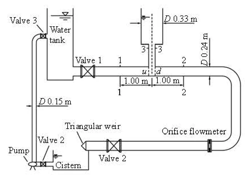
Fig.1 Schematic diagram of experimental setup
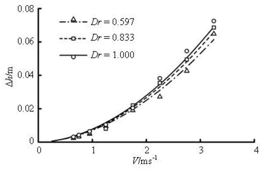
Fig.2 Comparisons of computed and measured head losses for the cases of different diameter ratios Dr, where the signs of various shapes are for computed results and the curves are for measured results
1. Model description
1.1 Numerical model
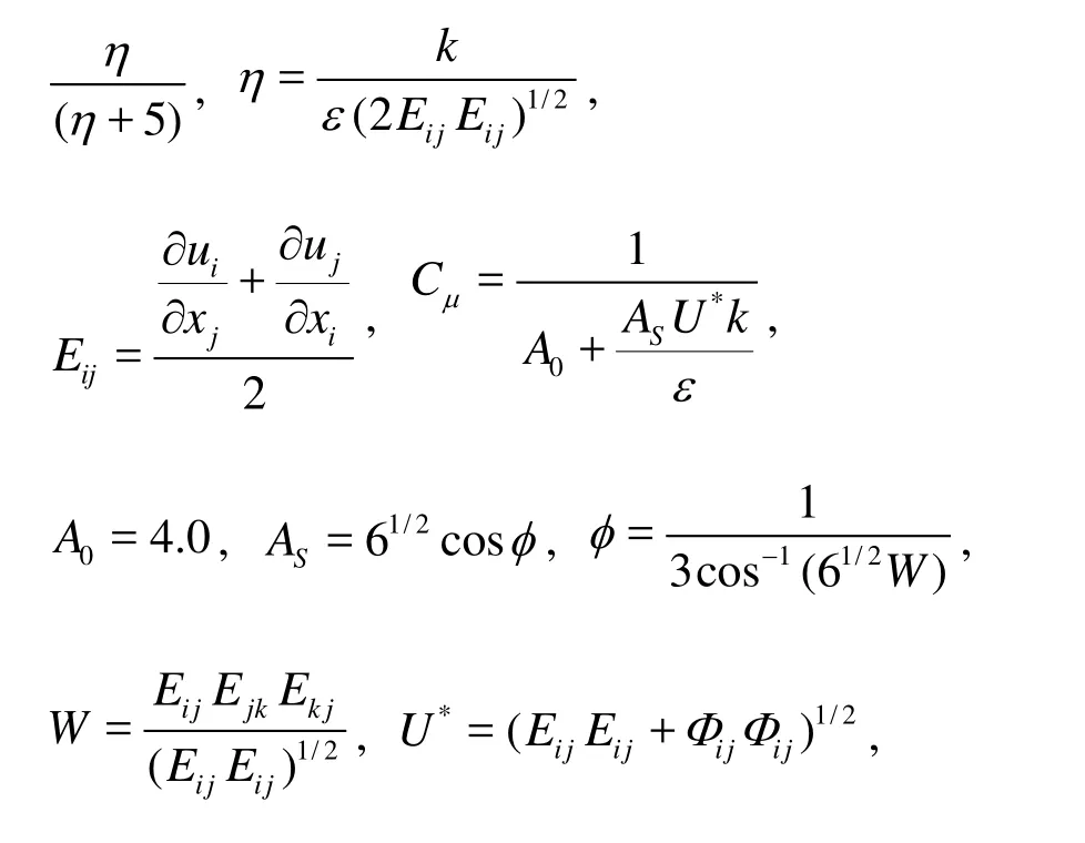
The flow is assumed to be steady, incompressible, isothermal, and Newtonian. The continuity equation, the momentum equation, and the equations fork andεin the realizablek-εmodel are:

respectively, where xiare the spatial coordinates, uiare the Reynolds-averaged velocity components, giare the body force components of unit mass, ρ is the fluid density, ν is the kinematic viscosity, P is the pressure, k is the turbulent kinetic energy, ε is the turbulent dissipation rate, the turbulence Prandtl numbers for k and ε areσk=1.0 and σε=1.2, respectively, C2= 1.90, C1is the maximum value between 0.43 andis the mean rate of the rotation tensor viewed in a rotating reference frame with angular velocity ωk.

In the numerical model, the control volume method is used together with the second order upwind scheme[17]. The SIMPLEC algorithm is used for the pressure coupling[18]. The upsteam boundary condition is set as the velocity inlet. At the downstream end, the pressure outlet is used. The Standard Wall Functions method is employed for the near-wall treatment of the turbulence flow.
1.2 Validation of numerical model
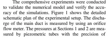

Figure 2 shows the local head losses between Sections 1 and 2, for the cases of different diameter ratios of the standpipe to the main duct (Dr= D3/ D1):Dr =0.597, 0.833 and 1.000. As can be seen, the computed results are in good agreement with the measured ones. The absolute error increases with the velocity, but the maximum relative error is still less than 10%. These differences may result from the measurement errors and the accuracy of the turbulence model.
2. Flow field characteristics
2.1 Flow patterns
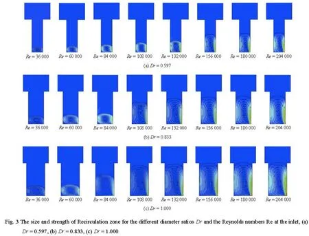
The fluid emerging from the main duct can not follow the abrupt change of direction of the boundary, consequently, the flow separates and an anticlockwiserecirculation zone is formed in the standpipe. Figure 3 illustrates parts of the numerical results. The steamlines and the velocity contour plots in this figure demonstrate that the size and the strength of the recirculation zone increase with Drand the Reynolds numbers at inlet (Re=VD1/ν,V and D1are the mean velocity and the diameter of the main duct). It can be seen in this figure that for the sameDrthe size and the strength of the recirculation zone increase withRe. For the sameRe, the size of the recirculation zone increases withDr. The detailed computed results indicate the increase in the size of the recirculation zone in the range of 60000 <Re <92000/Dr is more significant than that outside of the range.
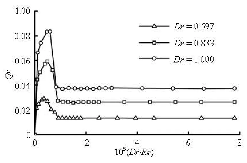
Fig.4 Variations of Qrwith Dr⋅ Re for Dr=0.597, 0.833 and 1.000

Fig.5 Variation of Qrwith Dr for Dr⋅ Re>92000
2.2 Recirculation flow rate
The recirculation flow rate Qschanges with the main duct flow rate Qand the diameter of the standpipe. Figure 4 shows the variations of the dimensionless flow rate(Qr= Qs/Q)against Dr⋅ Re . Here, Dr⋅ Re is the dimensionless product ofDrand Re, and represents the flow condition and the geometrical property of the model. It is observed that the flow-ratioQrincreases with Dr⋅ Rewhen0

Obviously,Qris approximately proportional to the square ofDr.
For the practical hydraulic engineering projects, the conditionDr⋅ Re>92000is always satisfied, so Eq.(5) could be used to estimate the steady-state recirculation flow rate for throttled surge tanks with standpipe.

Fig.6 Schematic diagram of flow patterns

Fig.7 Variation of α0with Dr for Dr⋅ Re>92000
2.3 Head loss coefficients
Based on the steamlines and the velocity contour plots in Fig.3, Figure 6 illustrates the flow patterns. The recirculation causes the dissipation of energy as heat, and consequently, the head losses between Sections uandd , Section 3 and Point a, and Section 3 and Pointb(Δhu-d,Δh3-a, and Δh3-b, where the subscripts are the location indices as shown in Fig.1). These head losses follow a square law, i.e.,Δh= αV2/2g. The coefficients corresponding to these head losses are represented by α0,α1and α2, respectively. Figure 7 shows the variation of α0withDr in the range Dr⋅ Re>92000. It is observed from this figure thatα0is proportional to Drapproximatively, and the best fitting formulae is

On the other hand, the piezometric pressures at Sectionsuandd are approximately equal to those at Pointsaandb , respectively. The computed results show that the following conditions As1/ AT= 8Dr/9and As2/ AT= Dr/9are always satisfied. The coefficientsα1and α2may be, therefore, obtained as illustrated in Fig.8. In this figure,α1and α2are approximately proportional toDrby using the piecewise functions. The same values ofDr at the boundary points are 0.225. Note that the condition As/ AT>0.15is always satisfied for throttled surge tanks with standpipe, that is to say, the condition of Dr>0.225always holds.
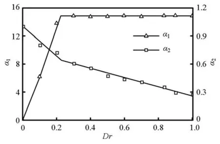
Fig.8 Variation of α1and α2with Dr for Dr⋅ Re> 92 000
3. Critical stability area
With Thoma’s assumption and considering the head loss for the recirculation zone, the dynamic equation of the fluid in the tunnel is
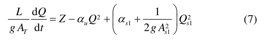
where L is the length of the tunnel,ATis the average cross-sectional area of the tunnel,Qis the discharge of the tunnel,Qs1is the recirculation flow rate upstream as shown in Fig.6,Zis the water level in the surge tank above the reservoir level (positive upward), αu= α + k / 2g, α is the head loss coefficient of the tunnel,α= α/2gA2,
s11 s1 α= α/2gA2, and g is the gravitational
s22 s2 acceleration.
The continuity equation for the junction of the tunnel and the standpipe is
where Qtis the turbine flow,Qs2is the recirculation flow rate downstream as shown in Fig.6, and F is the horizontal cross-sectional area of the tank.
By assuming the constant efficiency of the turbine, the constant hydraulic power equation therefore takes the form

where H0is the static head,αdis the head loss factor in the penstock, and the subscript “0” represents the steady-state value.
For the head losses at the junction of the tunnel and the standpipe, the following equation can be used

By rewriting Eqs.(7)-(10) in terms of small deviations,Δz,ΔQ,ΔQt, from the steady-state values, and neglecting terms of second and higher orders, the second-order differential equation forΔz is obtained. If the coefficient of the term d/(Δz)/dt in this equation is equal to zero, the oscillations are in a stable state. The resulting expression for the criticalstability area of the surge tank is consequently obtai- ned as follows

where the first fraction term is the Thoma critical sta-bility area,hw0is the head losses of the tunnel in the steady state, and hwm0is the head losses of penstocks in the steady state.
Substitution ofAs1/ AT=8 Dr /9,As2/ AT= Dr /9, and computed results of α1and α2into the termαs2/(αs1- αs2)of Eq.(11), we have

The term 1/2 gA2αof Eq.(13) is the ratio of the velocity head to the head losses in the tunnel. The comparison of this equation with the Thoma critical stability area indicates the critical stability area is re- duced. This reduction in the tank area is favorable to the economy of the construction. In general, the adva- ntage of this reduction is more significant for the low- head power plants.
4. Conclusion
In this study, the stability of the throttled surge tanks with standpipe is analyzed with consideration of the effects of the flow field characteristics in the steady state. The critical stability area is derived on the basis of the numerical results. The critical area presented in this study is smaller than the Thoma’s one, and is influenced by the diameter ratio and the ratio of the velocity head to the head losses in the tunnel. This reduction in the tank area is favorable to the economy of construction. In addition, the computed results show that there is an anticlockwise recirculation zone in the standpipe due to the abrupt change of direction of the boundary. The variation of the head loss coefficient at the junction is linearly related with the diameter ratio of the standpipe to the pipeline. The dimensionless recirculation flow rate is proportional to the square of the diameter ratio. The simulation results of the CFD could be used to calculate the critical stability area of the downstream throttled surge tanks with standpipe.
[1] CHAUDHRY M. H. Applied hydraulic transients[M]. 2th Edition, New York: Van Nostrand Reinhold, 1987, 333-376.
[2] CASARSA L., GIANNATTASIO P. Three-dimensional features of the turbulent flow through a planar sudden expansion[J]. Physics of Fluids, 2008, 20(1): 1-15
[3] ROY V., MAJUMDER S. and SANYAL D. Analysis of the turbulent fluid flow in an axi-symmetric sudden expansion[J]. International Journal of Engineering Science and Technology, 2010, 2(6): 1569-1574
[4] JAEGER C. A review of surge-tank stability criteria[J]. Journal of Basic Engineering, 1960, 82(4): 765-775.
[5] ANDERSON A. Surge shaft stability with pumped-storage schemes[J]. Journal of Hydraulic Engineering, ASCE, 1985, 110(6): 687-706.
[6] GARDEL A. Pressure drops in flows through T-shaped fittings[J]. Bulletin Technique De La Suisse Romande, 1957, 83(9): 123-130.
[7] LAI Xu, YANG Jian-dong and CHEN Jian-zhi. Effects of velocity and momentum exchange on critical stable sectional area of downstream throttled surge tank[J]. Journal of Energy Engineering, 2003, 129(3): 96-106. [8] LAI Xu, YANG Jian-dong and CHEN Jian-zhi. Critical stable sectional area of downstream throttled surge tank[C]. 4th ASME/JSME Joint Fluids Summer Engineering Conference. Honolulu, Hawaii, USA, 2003, 2885-2890.
[9] FERZIGER J. H., PERIC M. Computational methods for fluid dynamics[M]. 3th Edition, New York: Springer-Verlag, 2002.
[10] WILCOX D. C. Turbulence modeling for CFD[M]. 3th Edition, San Diego, USA: DCW Industries, Inc., 2006.
[11] SAMY M. E., MOFREH H. H. A comparative study of turbulence models performance for separating flow in a planar asymmetric diffuser[J]. Computers and Fluids, 2011, 44(1): 248-257.
[12] SAQR K. M., WAHID M. A. Comparison of four eddyviscosity turbulence models in the eddy dissipation modeling of turbulent diffusion flames[J]. International Journal of Applied Mathematics and Mechanics, 2011, 7(19): 1-18.
[13] NICHOLS R. H., NELSON C. C. Wall function boundary condition including heat transfer and compressibility[J]. AIAA Journal, 2004, 42(6): 1107-1114.
[14] CRAFT T. J., GANT S. E., IACOVIDES H. and LAUNDER B. E. Development and application of a new wall function for complex turbulent flows[C]. European Congress on Computational Methods in Applied Sciences and Engineering. Swansea, Wales, UK, 2001.
[15] CHENG Yong-guang, YANG Jian-dong. Hydraulic resistance coefficient determination of throttled surge tanks by means of computational fluid dynamics[J]. Journal of Hydraulic Engineering, 2005, 36(7): 792-797 (in Chinese).
[16] CAI Fu-lin, HU Ming and CAO Qing. Coefficients of head losses of throttled surge tanks with long linking pipe[J]. International Journal of Hydroelectric Energy, 2001, 19(4): 40-42.
[17] HUA Zu-lin, XING Ling-hang and GU Li. Application of a modified quick scheme to depth-averaged k-ε turbulence model based on unstructured grids[J].
10.1016/S1001-6058(13)60366-2
* Project supported by the National Natural Science Foundation of China (Grant No. 51079050) the Doctoral Innovation Foundation in Jiangsu Province (Grant No. 2017-B0803338).
Biography: AN Jian-feng (1981-), Male, Ph. D. Candidate
ZHANG Jian,
E-mail: jzhang@hhu.edu.cn
猜你喜欢
杂志排行

水动力学研究与进展 B辑的其它文章
- Hydrodynamic modeling of cochlea and numerical simulation for cochlear traveling wave with consideration of fluid-structure interaction*
- Orientation of the fiber suspending in the flow through a tube containing a sphere*
- Numerical analysis of vortex core phenomenon during draining from cylinder tank for various initial swirling speeds and various tank and drain port sizes*
- Radiation and diffraction analysis of a cylindrical body with a moon pool*
- Heat transfer characteristics in micro-fin tube equipped with double twisted tapes: Effect of twisted tape and micro-fin tube arrangements*
- Stochastic simulation of fluid flow in porous media by the complex variable expression method*