Torque Ripple Suppression Control Strategy for Brushless Integrated Starter/Generator Wound-Field Synchronous Motor
2012-07-25LUOGuangzhao骆光照ZHANGWeiwei张围围YANGNanfang杨南方MAPeng马鹏LIUWeiguo刘卫国
LUO Guang-zhao(骆光照),ZHANG Wei-wei(张围围),YANG Nan-fang(杨南方),MA Peng(马鹏),LIU Wei-guo(刘卫国)
(School of Automation,Northwestern Polytechnical University,Xi’an 710072,Shaanxi,China)
Introduction
With the rapid development of informationization and electrification of armored vehicles,more and more vehicular electronic equipment is springing up.They need great electric power.Therefore,the integrated starter/generator(ISG)system is one of optimal solutions because of its compact structure,high reliability,multiple function and energy recycling.
A novel concept of ISG is brushless wound-field synchronous motor(WFSM).It consists of an armature rotary single-phase AC excited machine(exciter),a rotary rectifier and a three-phase wound-field synchronous machine(main machine).They are coaxial and integrated.The exciting flux of main machine is adjusted indirectly by changing the field current of exciter to eliminate the brush set and effectively improve reliability and maintainability.However,the coaxial connection of the exciter and main machine leads to the mutual influence between them.Especially,in the start process of main machine,the exciter is usually excited by single phase AC current and then the rectified induced current is used to excite the main machine.In such situation,the fluctuation of field current of main machine causes the ripples of flux linkage and electromagnetic torque inevitably.It may lead to the engine ignition failure and even damage.Thus,it becomes a key issue to realize smooth start of the synchronous machine with fluctuated field current[1-2].
Nowadays,the vehicular ISG mainly adopts permanent magnet synchronous motor(PMSM),brushless DC motor(BLDCM),inductive motor(IM)and so on[1-5].There has been a lot of literature discussed the issue.In Ref.[6],the coordinate control of start process of ISG using PMSM and engine was studied,and experiments were given to verify the feasibility of the proposed strategy.In Ref.[7],the authors conducted comparative investigated the performances of PMSM and IM adopted in ISG comparatively,and proposed fuzzy control strategy.In Ref.[8],WFSM adopted in ISG was proposed for an armored vehicle,but the detailed analysis for the start process was absent.Anyway,there are still many researches to be conducted in order to adopt WFSM in ISG used in armored vehicles.
In this paper,the control of start process of main machine under fluctuated field current is investigated,and the compensation of flux is analyzed.A compensation method ford-axis current to minimize the torque and flux linkage ripples is proposed to start the main machine smoothly.Simulation and experiment results verify its feasibility.
1 Analysis and Modeling for BLISG Start
1.1 Start Analysis
The simple structure of BLISG is shown in Fig.1.The field current of the main machine is a direct current which rectified by a rotary rectifier.The main machine starts like a motor,and transits from the motor to the generator after reaching a certain speed.

Fig.1 Structure of brushless ISG system
The system operation can be divided into two stages.Firstly,the main machine works like a motor to drive the engine;secondly,the main machine works like a generator after the engine runs normally.In the first stage,the exciter generates an alternating current in the rotor to the rotary rectifier when a single-phase AC voltage is put into its excitation windings.And the main machine starts with an impulsive DC field current from the output of rotary rectifier.Then,the proportion of the DC component of the single-phase field current is regulated to improve the excitation intensity when the speed of the main machine gradually increases.The AC component decreases gradually to zero when the main machine reaches a certain speed,and finally,the DC excitation componentremains only.In this process,the speed of the main machine increases gradually to the ignition speed of the engine,then the engine starts successfully at the end of first stage.In the second stage,the main machine transits from the electromotion state to the generation state when the engine starts smoothly and the speed increases gradually.The engine drives the main machine to generate electric power for the whole vehicle.
1.2 Modeling of Electric Excited Synchronous Motor
The voltage equations of WFSM is a set of differential equations with variable parameters in ABC threephase physical phase coordinates,and the coefficients of the differential equation vary with the relative position of rotor and stator.Considering the damper windings on the rotor,the mathematical model has features of nonlinearity,multivariate,strong coupling and so on.
To simplify the equations,the model in the physical phase coordinates can be transformed linearly tod-qcoordinate system by using the coordinate transformation theory of the motor.Assuming the sinusoidal distribution of three-phase stator windings in space,ignoring the high frequency harmonics,magnetic saturation,iron loss and parameters perturbation caused by temperature,and also considering the effects of the damping winding,the mathematical model ind-qcoordinate system can be given as follows.
The voltage equation is
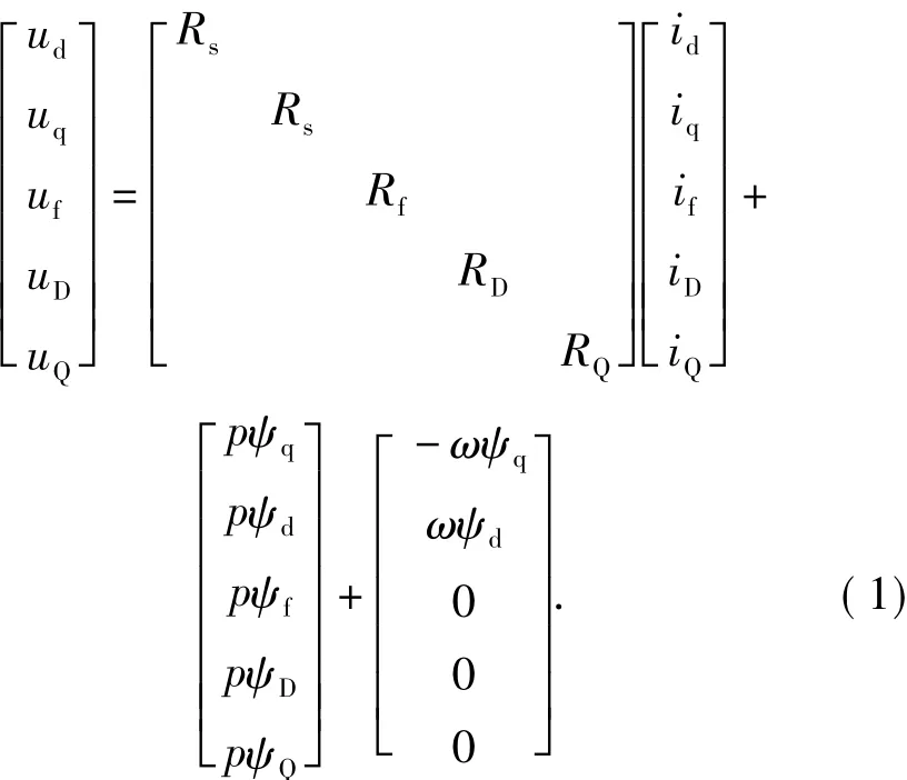
whereRs,Rf,RDandRQare resistances of armature,excitation,d-andq-axis damping windings,respectively;ud,uq,uf,uDanduQare the voltages ofd-,q-axis,excitation,d-andq-axis damping windings,respectively;id,iq,if,iDandiQare the currents ofd-,q-axis,excitation,d-andq-axis damping windings,respectively;ψd,ψq,ψf,ψDandψQare the flux linkage ofd-,q-axis,excitation,d-andq-axis damping windings,respectively;ωis the rotor’s angle frequency;p=d/dtis a differential operator.
The flux linkage equation is
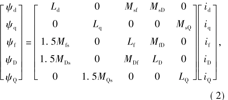
whereLdandLqare the equivalent inductancesd-andq-axis windings;LDandLQare the inductances ofdandq-axis damping windings;Lfis the inductance of excitation winding;Msf=Mfsis the mutual inductance betweend-axis armature winding and excitation winding;MsD=MDsis the mutual inductance betweend-axis armature winding andd-axis damping winding;MsQ=MQsis the mutual inductance betweenq-axis armature winding andq-axis damping winding;MDf=MfDis the mutual inductance between excitation winding anddaxis damping winding.
The electromagnetic torque equation is
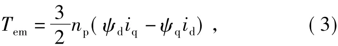
whereTemis the generated electromagnetic torque;npis the pair number of poles.
According to Eq.(2),the electromagnetic torqueTemcan be divided into basic electromagnetic torqueTem1,additional electromagnetic torqueTem2generated by the damping winding and torque ripple ΔTamproduced by the excitation fluctuation.Then,the electromagnetic torque can be expressed as

ΔTamneeds to be analyzed according to the ripple amplitude of field current,while the excitation ripple can be equivalent to the effect of a flux ripple in theψddirection,denoted as Δψd,and then ΔTamcan be written as

In addition,the damping winding can generate asynchronous starting torque in the start procedure.It also reduces the air-gap magnetic field dynamics in a certain extent.When the machine operates like a generator,the damping winding can weaken the negative sequence components of the magnetic field and reduce the higher harmonic current amplitude.Therefore,the influence of damping winding has to be considered in start process.
2 Control in Start Process
2.1 Torque-velocity CharacteristicsMatch Between Engine and ISG
Since the main machine and the engine is an interrelated combination in the starting process,it is necessary to match the output characteristics of main machine and the starting characteristics of engine to ensure the stability and reliability.The parameter match includes three parts,the starting power,torque and speed.
2.1.1 Power characteristics match
The constraint for match between the main machine power characteristics and the engine starting performance is[9]

wherePmis the starting power of main machine;Peis the starting power of engine.
The vehicle is required to drive the engine up to a certain speed within the specified time,so the main machine must have the ability to start the engine at a certain short time.The engine’s starting powerPecan be expressed as
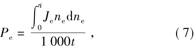
whereJeis the rotary inertia of the engine;neis its ro-tary speed;niis its idle speed;tis its starting time.
2.1.2 Torque and speed characteristics match
The solid line in Fig.2 shows the starting characteristics of the engine.For the engine starting,the mechanical properties of the main machine are required as follows.
1)The system can overcome the staticfriction moment in the static state.
2)The torque output can meet the requirements of the peak torque point of the engine in the constant torque output section.
3)The system has the field-weaken ability to run in high speed and drive the engine to releasing speed.
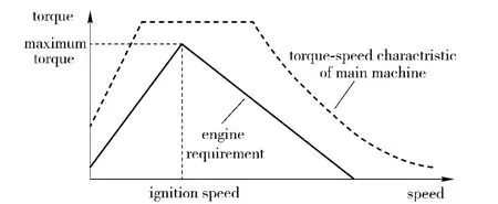
Fig.2 Torque characteristics of engine and main machine
According to the analysis above,the torque output curve of the main machine can be planed as the dash line shown in Fig.2.The frequency conversion can be used to increase the starting torque and accelerate in the low speed segment.The maximum torque output has to be achieved in the constant torque segment.The field can be weakened for high speed operation in the constant power segment.
2.2 Field Oriented Control with Flux Linkage Compensation
There are two requirements for BLISG to start enginesuccessfully.First,BLISG has to supply enough electromagnetic torque;and second,the torque control has to be stable,because the higher torque ripple will lead to the ignition failure or damage of engine.The first requirement can be satisfied by increasing the power range of WFSM,while the second requirement must be satisfied by improving the normal control method in order to minimize torque ripple.The field oriented control(FOC)has perfect torque control performance in lower speed compared with the direct torque control(DTC).Hence,it is suitable for start control of BLISG system.
The compensation of flux linkage will be conductedin the basic FOC method.Usingd-axis compensation,a relative constant flux linkage can be obtained when the field current fluctuates.The block diagram of the proposed control is shown in Fig.3.

Fig.3 Block diagram of flux linkage compensation FOC
The field current of main machine can be divided into rotating component and inductive component,if the commutation of rotate rectifier is ideal.The rotating component is used to identify the contribution of exciter in field current of main machine;and the inductive component represents the contribution of armature current of main machine,due to armature reactive.
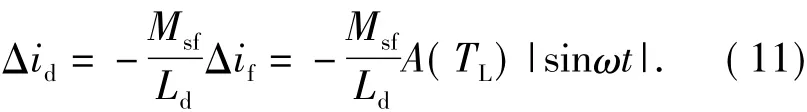
As for the rotating component,the terminal voltage of exciter is proportional to the rotary speed of rotor,and then the three phase voltages are rectified to DC voltage using as exciting voltage of main machine.Therefore,adjustment of field current of main machine can be realized by controlling the field current of exciter.For the inductive component,it depends upon the load torque and rotor angle frequency,due to it is generated by armature reactive in main machine.According to above analysis and some experiment data,the field current of main machine can be expressed as

whereC(ω)is the rotating component which increases with the increase of rotor speed and gradually retain constant due to saturation of magnet field in motor;A(TL)is the magnitude of inductive component changing with the load torque;ωis the rotor angle frequency;presents the rotating AC component;Δifpresents the inductive DC component.
2.3 d-axis Flux Linkage Compensation
According to Eq.(8),the torque and flux linkage ripple is generated by fluctuation of AC component.Therefore,a good torque and flux linkage performance can be obtained by compensatingd-axis current.d-axis flux linkageψdcan be expressed as

where Δidis the compensation current ofd-axis current.To makeψdkeep constant,the following equation must be satisfied

Then,the compensation current can be written as
3 Simulation of BLISG Starting Control with Flux Compensation
The starting process of main electric machine with variable magnetic flux can be simulated by using Matlab/Simulink,for the proposed mathematical model,control strategy and output characteristics of the WFSM.The flux linkage compensation module is shown in Fig.4.

Fig.4 Flux linkage compensation module
Build the excitation module according to Eq.(8),and obtain the field current,as shown in Fig.5.
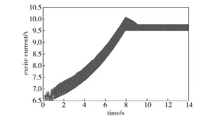
Fig.5 Field current
For the field current above,the starting process of the main machine can be simulated in two situations,i.e.with and without magnetic flux compensation,as shown in Fog.6 and 7.
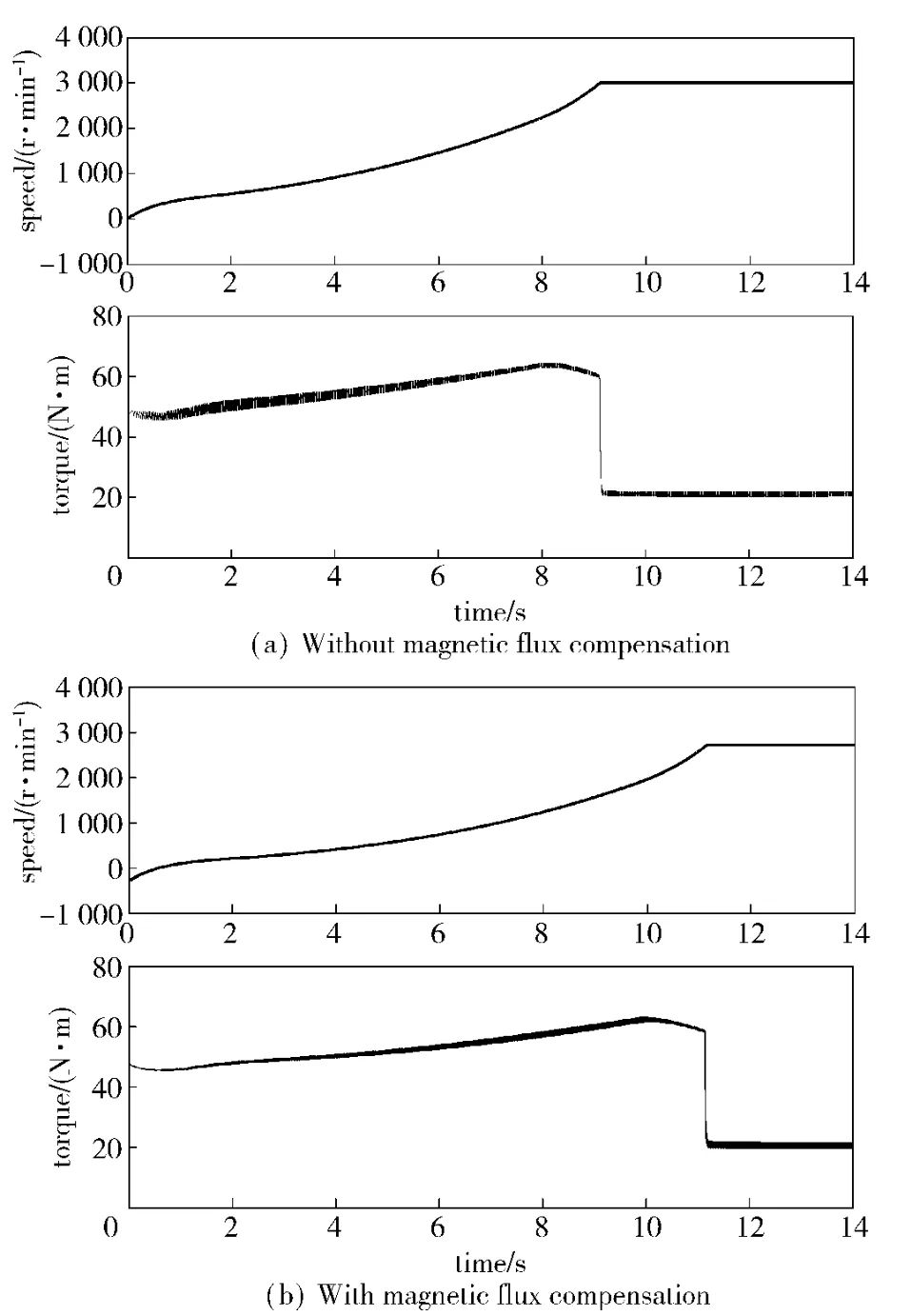
Fig.6 Speed and torque in starting process
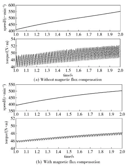
Fig.7 Speed and torque in initial start
It can be seen from the figures that the torque rip-ple is about 6%of total torque in average without the flux linkage compensation,while it reduces to about 2%when the flux linkage compensation is adopted.Especially,the torque ripple can be reduced by more than 70% when the speed of the motor lower than 1 000 rpm.
In addition,the start time without magnetic flux compensation is 25%shorter than that with magnetic flux compensation according to Fig.6.In fact,this uncertain start time changes along with the different RMS of excitation ripple.And it will lead to uncertainty of combustion and decrease the reliability of the starting process.
It can be known from the simulation results that,by using the method,the engine can be driven to the firing speed,the ripple of the torque is suppressed in low-speed,and the starting performance is improved significantly.And,the starting time with magnetic flux compensation almost keeps constant in different excitation ripples.
4 Experiment Analyses
A preliminary experiment is carried out by using a WFSM to verify the proposed flux linkage compensation FOC.The ratio of ripple’s amplitude to the DC field current component varies from 6.3%to 23.7%.The testes motor’s parameters are shown in Tab.1.The experimental apparatus is shown in Fig.8.

Tab.1 Parameters of tested synchronous motor
The experiment results are shown in Fig.9.The waveforms of the field current,A phase current of the main machine and B phase current of the main machine are shown in channel 1,2 and 3,respectively.It can be seen from Fig.9 that the magnetic flux compensation can effectively improve the three-phase current of the main machine.It also can be inferred that the ripples of torque and speed are reduced.Because of the limitation of experiment condition,the torque of the main machine can not be directly measured.
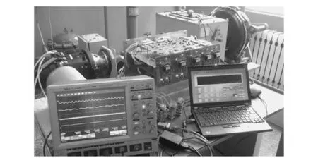
Fig.8 Experiment apparatus

Fig.9 Phase current
The speed of the motor in start process is shown in Fig.10,the dashed curve is the given speed,and the black curve is the actual speed.
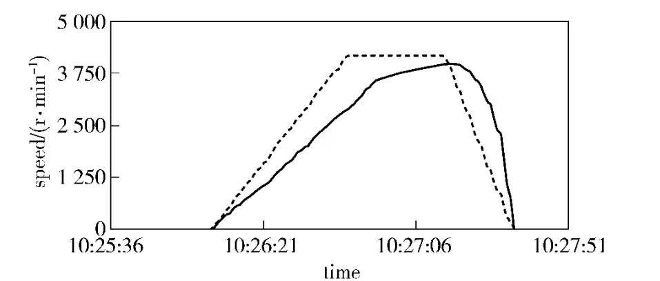
Fig.10 Rotary speed of motor
The experiment results show that the magnetic flux compensation in the field oriented control strategy can effectively suppress the torque ripple caused by flux linkage and ensure the motor start smoothly and reliably.It is proved that the field oriented control with flux linkage compensation in the brushless ISG system is feasible.
5 Conclusions
In this paper,the starting process of the brushless ISG system is analyzed.To solving the flux ripple caused by the fluctuated field current,a flux linkage compensation FOC is proposed.Comparing the traditional FOC with the proposed method,it is proved that the flux linkage compensation can greatly reduce the torque ripple in the motor starting process and improve the stability and reliability of the system.
[1]ZHANG Bo,ZHU Xiao-yong,LI Quan,et al.An integrated starter-generator based on flux memory machines for hybrid electric vehicles[J].Electrical Machines and Systems(ICEMS),2011,(20-23):1-4.
[2]Jain A K,Mathapati S,Ranganathan V T,et al.Integrated starter generator for 42-V powernet using induction machine and direct torque control technique[J].IEEE Transactions on Power Electronics,2006,21(3):701 -710.
[3]CAI W.Comparison and review of electric machines for integrated starter alternator applications[J].Industry Applications Conference,2004,lvi+2822:3-7.
[4]LIU Chun-hua,Chau K T,JIANG J Z.A permanentmagnet hybrid brushless integrated starter-generator for hybrid electric vehicles[J].IEEE Transactions on Industrial Electronics,2010,57(12):4055 -4064.
[5]Chau K T,Chan C C,LIU Chun-hua.Overview of permanent-magnet brushless drives for electric and hybrid electric vehicles[J].IEEE Transactions on Industrial Electronics,2008,55(6):2246 -2257.
[6]LU Zhong-hua,CHENG Xiu-sheng,FENG Wei.Coordinated control study in engine starting process of hybrid vehicle[C]∥Proceedings of 2010 IEEE International Conference on Information and Automation,2010:20 -23,2111-2116.
[7]Williamson S S,Khaligh A,Emadi A.Impact of utilizing selective motor topologies and control strategies on the overall performance of integrated starter alternator(ISA)based HEVs[J].Electric Machines & Drives Conference,2007,1:3 -5,134 -139.
[8]ZHANG Ning.New type power supply system for armored vehicle[J].Ordnance Industry Automation,2005,24(5):31-32.(in Chinese)
[9]HUANG Da-xing,HE Ren.Parameters matching on engine and ISG motor for city bus[C]∥Proceedings of International Conference on Electrical and Control Engineering,2010:25 -27,5388 -5391.
杂志排行

Defence Technology的其它文章
- An Investigation on a Tin Fixed Abrasive Polishing Pad with Phyllotactic Pattern for Polishing Wafer
- An Approximate Calculation Method for Lateral Trajectory Correction
- Lift Enhancement and Oscillatory Suppression of Vortex-induced Vibration in Shear Flow by Loentz Force
- A Study on Criteria for Barrel Lifetime
- Research on Microcrack Extension Mechanism of SiCp/Al in the Machining Process
- Molecular Dynamic Simulation for HMX/NTO Supramolecular Explosive