Acquisition, Pointing and Tracking System for Shipborne Space Laser Communication without Prior Information
2022-08-08WANGXiaokang王小康SHANGJianhua尚建华LUOYuanHEYan
WANG Xiaokang(王小康), SHANG Jianhua(尚建华)*, LUO Yuan(罗 远), HE Yan(贺 岩)
1 College of Information Science and Technology, Donghua University, Shanghai 201620, China 2 Key Laboratory of Space Laser Communication and Detection Technology, Shanghai Institute of Optics and Fine Mechanics, Chinese Academy of Sciences, Shanghai 201800, China
Abstract: A space laser communication acquisition, pointing and tracking(APT)system based on the beacon laser is designed without prior information. And then, a new target scanning method and a pointing and tracking algorithm are proposed. The target scanning mode is the round-trip triangular wave scanning, and it means that scanning track of the PAN-TILT platform follows the triangular wave repeatedly. For the pointing and tracking algorithm, the beacon laser is used as the auxiliary aiming light source. The position of the beacon laser in the viewfield of the complementary metal oxide semiconductor(CMOS)camera is calculated by the centroid algorithm. In order to realize the target tracking, the joint control method of the angle control and the angular velocity control is used. The simulation and experimental results show that the APT system can achieve full coverage scanning in the scanning area and capture the target in one scanning cycle successfully. After capturing the PAN-TILT platform, the pointing and tracking algorithm can track the PAN-TILT platform quickly and accurately, and the tracking accuracy is up to 0.22 mrad.
Key words: space laser communication; acquisition, pointing and tracking(APT); triangular scanning method; angle control; angular velocity control
Introduction
Laser communication has been widely used in both military and civilian fields because of the advantages of high speed, large capacity, strong confidentiality and strong anti-interference ability.A space laser communication system is mainly composed of the transmitting system, the receiving system, and the beam acquisition, pointing and tracking(APT)system.Among them, the APT system is responsible for accurate alignment and high-precision tracking of a laser communication terminal which directly affects the quality of space laser communication[1].
The researchers have carried out a lot of work related to the space laser communication APT system.In 1995, the spaceborne optical transceiver LCE with the laser communication system ETS-VI was conducted by the test satellite in Japan.In the following year,the two-way inter-satellite laser communication experiments were carried out by the Jet Propulsion Laboratory of America.The fine tracking field of the LCE is 500 μrad with the alignment accuracy of 1 μrad and the tracking bandwidth of 300 Hz[2-3].From the year of 2013 to 2014, the lunar laser communications demonstration(LLCD)system of National Aeronautics and Space Administration(NASA)of America realized space laser communication successfully.For the APT system of the LLCD, the beacon laser with the divergence angle from 45 mrad to 100 mrad was used as the auxiliary aiming light source, and the tracking and aiming accuracy of this APT system was lower than 1 μrad[4-6].Since the year of 2014, researchers from Xi’an University of Technology has carried out a series of research on the low earth optical communication[7-10].Using the two-step alignment method of beam angle alignment and position alignment, the designed APT system with a dual detection structure achieved an angle tracking accuracy of 34.6 μrad and a position tracking accuracy of 35 mm.In addition, the acquisition, alignment and tracking of the beacon laser could be realized when the distance is 1.3 km.In 2017, Liu[11]analyzed the capture performance based on the beacon-free optical APT system.According to the results of theoretical analyses and simulation experiments, it was found that the required capture time for step scanning can be further shortened by using the mode of beacon-free capturing.
Herein, based on the application requirements of the shipborne laser communication APT system, a round-trip triangular wave scanning method with high acquisition efficiency and a high-speed tracking algorithm for ground targets without prior information are designed.In the process of target acquisition, the two-dimensional(2D)PAN-TILT platform is used as the carrier, and the beacon laser is played as the auxiliary aiming light source.Firstly, the complementary metal-oxide-semiconductor(CMOS)camera scans and captures the beacon laser by reciprocating triangular wave.Secondly, for the target tracking and aiming, the centroid algorithm is used to obtain the position of the beacon laser in the viewfield of the CMOS camera.Finally, the angular position and the angular velocity of the PAN-TILT platform is controlled according to the position information, so as to realize high-precision and high-speed tracking.
1 Structure Design of APT System Terminal
As shown in Fig.1, the shipborne laser communication APT system has two terminals with the same structure and working process.The terminals are mainly composed of the transmitting unit and the receiving unit of the beacon laser, the 2D PAN-TILT platform movement unit, and the main control unit of industrial computer.After terminal A transmitting the beacon laser A, the CMOS camera in the receiving unit of terminal B receives the beacon laser, and the accurate position information of the spot in the viewfield of the CMOS camera can be obtained with the help of the centroid algorithm.Then, according to the obtained spot position information, the industrial computer in terminal B controls the angular position and the angular velocity of its 2D PAN-TILT platform, and finally realizes the rapid tracking and aiming of the target PAN-TILT of terminal A.The scanning resolution of the 2D PAN-TILT platform in the system is 1 920×1 200 pixels.Meanwhile, terminal A captures and tracks the target PAN-TILT in terminal B according to the same workflow.
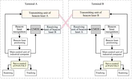
Fig.1 Composition of shipborne laser communication APT system
2 Target Scanning and Capturing
In this APT system, omnidirectional scanning is required in the horizontal direction, and the corresponding scanning range in the pitching direction is 20°.There are three kinds of scanning methods commonly used in the space laser communication system: the rectangular scanning, the spiral scanning, and the spiral rectangular scanning.These methods mentioned above require a long scanning period, and cannot satisfy the application requirements of scanning in a large unknown area without prior information[6].Therefore, a reciprocating triangular wave scanning method is proposed in this paper.As shown in Fig.2, the 2D PAN-TILT platform moves at a constant speed in the pitching direction and the horizontal direction, respectively, and its final scanning track is similar to the reciprocating motion of the triangular wave.Considering the jitter of the platform itself and the influence of other interference factors, in order to make sure that the viewfield of the CMOS camera can cover the arranged scanning area during scanning, the scanning overlapping area size should be set reasonably.

Fig.2 Principle reciprocating triangular wave scanning
The selection of the scanning speed and the scanning range of the 2D PAN-TILT platform is very critical.Besides ensuring the full coverage scanning of the CMOS camera, the time required for target acquisition should be shortened as much as possible.Therefore, we should not only consider the full coverage scanning of the CMOS camera, but also reduce the target acquisition time at the same time.To ensure that the detection area of the CMOS camera can cover the range to be scanned in an all-round way, the viewfield of the CMOS camera needs to be in the time interval of two adjacent frames of images Δt.In this way, there will be an overlap in the pitching direction.
When the viewfield angle of the CMOS camera in the pitching direction isθy, the scanning angular velocity in the pitching direction of the 2D PAN-TILT platformωyshould satisfy
ωy·Δt≤θy.
(1)
If the pitching scope to be scanned is fromybegintoyend, in order to enable the horizontal viewfield of the CMOS camera to overlap each other, the time intervaltof the two adjacent top(or bottom)peaks of the 2D PAN-TILT platform triangular wave scanning track is described as
(2)
For the viewfield angle of the CMOS camera in the horizontal direction isθx, the scanning angular velocity in the horizontal direction of the 2D PAN-TILT platformωxneeds to satisfy
ωx·t≤θx.
(3)
Since the specific position of the target PAN-TILT of the other side cannot be known, the horizontal scanning range is set from-180° to +180°, and the pitching direction scanning range is set to a smaller value.It can be seen from Eq.(1)thatωydepends on the viewfield of the CMOS camera and Δt.Forωx, it is limited by the scanning range in the pitching direction, the angular velocity of the pitching scanning, and the viewfield of the CMOS camera.For practical application,ωyof the 2D PAN-TILT platform at both ends can be set to be the same value, whileωxneeds to be set separately.So as to obtain the best scanning and acquisition performance, the simulation experiments are conducted repeatedly.Thus, whenωAxandωBxmeet the golden ratio as shown in Eq.(4), the APT system achieves the best performance.
ωBx=0.618ωAx.
(4)
To verify the target acquisition probability of the reciprocating triangular wave scanning method, the mutual scanning and acquisition process of the 2D PAN-TILT platform at both ends is simulated according to the flow shown in Fig.3.In the calculation, according to the actual device parameters of the CMOS camera, the field angles in the horizontal direction and the pitching direction are set to be 6.112° and 3.820°, respectively.The divergence angle of the beacon laser is set to 3.000°.The horizontal scanning range and the pitching scanning range of the 2D PAN-TILT platform at both ends are uniformly set from-180° to +180°, and-10° to +10°, respectively.ωAxandωAyare 13.00(°)/s and 90.00(°)/s, respectively.ωBxandωByare 8.03(°)/s and 90.00(°)/s, respectively.Due to that the time interval between two adjacent frames of the CMOS camera used in the system is about 40 ms, the time iteration step during the target scanning and acquisition simulation is set as 40 ms for the scanning and acquisition simulation.

Fig.3 Simulation process of target scanning and acquisition
Figure 4 shows the simulation results of target scanning and acquisition.The abscissa represents the number of time iterations, and the ordinate represents the acquisition status.The value of the capturing flag value 1 means that acquisition is successful.It is obvious that the 2D PAN-TILT platform at both ends is successfully captured for the first time after 400 time iterations(about 16 s).In the range of 5 000 time iterations(200 s), a total of five acquisitions are realized.Therefore, the round-trip triangular wave scanning method has a high acquisition efficiency.It can not only capture the target PAN-TILT for many times, but also take a short time for the first acquisition.

Fig.4 Simulation results of target scanning and acquisition
3 Target Tracking and Aiming
In the APT system, the angle control mode and the angular velocity control mode are normally used to realize the motion control of the PAN-TILT.The stability of the angle control mode is satisfied, but the response speed is slow.However, the angular velocity control mode has a high response speed and poor stability.Therefore, in order to realize the accurate control of the fast-moving PAN-TILT, the angle control mode and the angular velocity control mode are applied to track and aim the target.The flow of tracking and aiming joint control algorithm based on angle control and angular velocity control is shown in Fig.5.The viewfield of the CMOS camera is 1 920×1 200 pixels.For the circular area with the center of the viewfield as the circle center and the radius of 300 pixels, the angular velocity control method is used to track and aim the target.Otherwise, for the viewfield of the CMOS camera outside the circular area, the angle control method is used to track and aim the target.

Fig.5 Tracking and pointing control algorithm based on the angle control and the angular velocity control
In the angle control mode, after the CMOS camera captures the beacon laser emitted by the target PAN-TILT, the position information of the beacon laser spot in the viewfield of the CMOS camera is calculated with the help of the centroid algorithm[12-13].Then, the angle of the PAN-TILT is controlled to stabilize the target PAN-TILT beacon laser at the center of the camera viewfield, and the aiming of the target PAN-TILT is realized finally.
Different from the angle control mode, the angular velocity control mode controls the angular velocity of the PAN-TILT.Since the angular position information of the target PAN-TILT beacon laser spot in the viewfield of the CMOS camera is obtained by the centroid algorithm, the angular velocity needs to be converted into the angle so as to stabilize the beacon laser in the center of the viewfield of the CMOS camera.Firstly, the position offset(px,py)between the current beacon laser spot and the center of the CMOS camera viewfield is calculated.Secondly, the difference(Δpx, Δpy)between the offsets at the current time relative to the previous time is obtained.Thirdly, based on four parameters mentioned above, the digital incremental PI algorithm[14-15][shown in Eq.(5)]is used to drive 2D PAN-TILT platform of own side to the target PAN-TILT beacon laser spot at an appropriate speed(vx,vy), and then stabilize the beacon laser at the center of the field of own CMOS camera.Finally, the pointing and tracking of the target PAN-TILT is realized.
(5)
wherekpis the proportional coefficient, andkiis the integral coefficient.
To verify the effectiveness of the above-mentioned control algorithm, the algorithm was simulated and verified in Matlab.Since the same digital incremental PI control algorithm is applied in both the pitching direction and the horizontal direction, herein only one dimensional direction needs to be simulated.The simulation shows that whenkp=1 andki=11, the performance of the digital incremental PI control algorithm is optimal.The corresponding changes of the angle deviation and the angular velocity are shown in Fig.6.The abscissa presents the number of time iterations, and the time corresponding to each time iteration is 40 ms.At the initial moment, if there is an angle deviation, an angular velocity in the opposite direction will be output to the own gimbal to compensate for the current angular deviation, and the angular velocity is related to the angle deviation.Consuming 20 time iterations(about 800 ms), the angle deviation is adjusted to 0, and the angular velocity is no longer required to be compensated at this time.Meanwhile, the angular velocity is also adjusted to 0.
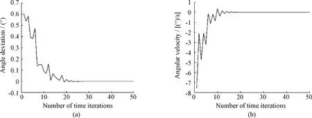
Fig.6 Simulation results of angular velocity control:(a)angle deviation;(b)angular velocity
4 Experimental Results and Analyses
In practical application, the initial position and start-up time of terminal A and terminal B of the APT system are different.And the azimuth angle of the tracked PAN-TILT is also unknown.In the experiment, the distance between the 2D PAN-TILT A and B(shown in Fig.7)is set to 15 m in the labratory,ωAyandωByare set to be 90.00(°)/s, respectively,ωAxis set to be 13.00(°)/s, andωBxis 0.618 times ofωAx.In addition, the viewfield angle of the CMOS camera in the horizontal direction and the pitching direction is 6.112°, and 3.820°, respectively, and the divergence angle of the beacon laser is 3.000°.This short-distance indoor experiments is able to prove the effectiveness of the designed method and algorithms to some extent.And the corresponding results are great important foundation for further improving and adjusting system parameters and algorithms.

Fig.7 Lab experimental platform for the APT system located on the other 2D PAN-TILT platform:(a)2D PAN-TILT A;(b)2D PAN-TILT B
The scanning ability of the APT system is tested firstly.As shown in Table 1, four kinds of scanning ranges are set.The pitching scanning range of the 2D PAN-TILT A and B is from-10° to +10°, and the horizontal scanning range includes four conditions.For each scanning range, 10 tests are carried out, and the total 10 results are averaged to obtain the average capture time of the APT system.Meanwhile, the capture probability is also obtained.It can be seen from Table 1 that when the pitching scanning range of the scanned area remains unchanged, the smaller the horizontal scanning range, the shorter the average acquisition time of the APT system.When the horizontal scanning range is from-180° to +180°, the average acquisition time of the APT system is the longest, namely 56.4 s.If the approximate orientation of the target PAN-TILT is known, the horizontal scanning range of the APT system can be reduced, which will shorten the average acquisition time greatly.In addition, the capture probability will decrease along with the scanning range increase.However, the capture probability can be up to 80.00%, even though the horizontal scanning range is from-180° to +180°.

Table 1 APT system capture performance
In order to obtain the performance of the designed space laser communication APT system located on the shipboard, the PAN-TILT B is loaded on the other 2D PAN-TILT platform as shown in Fig.7(b), whose angular velocities in horizontal and pitching directions are 4.00(°)/s.During the test, the APT system and the 2D PAN-TILT platform are operated at the same time.Under the condition that the beacon laser is not blocked, the 2D PAN-TILT A and B can realize mutual alignment for a long time which proves that the control of tracking and aiming is effective.
The pixel offset is shown in Fig.8.The abscissa is the number of time iterations(the time corresponding to each iteration is 40 ms), and the ordinate is the number of pixel offset.The pixel offset presents the position deviation of the beacon laser from the center of the CMOS camera viewfield, and the pixel offset is always less than 4 pixels during the process of target tracking and aiming.Since the actual CMOS camera tracking accuracy is about 0.055 mrad per pixel, correspondingly, the tracking accuracy of the designed APT system is between 0 and 0.220 mrad.Besides, when the pixel offset is positive, the beacon laser moves away in one direction.On the contrary, the beacon laser moves away in the opposite direction.

Fig.8 Number of pixel offset
5 Conclusions
In this paper, the APT system of space laser communication is studied in detail.The high-precision scanning method based on a round-trip triangular wave scanning and the pointing and tracking algorithm combining the angle control and the angular velocity control are proposed.The simulation and the lab experimental results show that the scanning method is able to successfully capture the target in one scanning cycle without any prior information and can provide short scanning time and high target acquisition probability.After capturing the target PAN-TILT which locates on the other 2D PAN-TILT platform simulating the shipboard, the joint tracking and the aiming algorithm can track the target PAN-TILT quickly and accurately, and the tracking accuracy is between 0 and 0.220 mrad.In order to further verify the capabilities of the designed APT system, the following work will focus on the outdoor performance tests.
杂志排行

Journal of Donghua University(English Edition)的其它文章
- Three-Dimensional Model Reconstruction of Nonwovens from Multi-Focus Images
- Toughness and Fracture Mechanism of Carbon Fiber Reinforced Epoxy Composites
- Three-Dimensional Metacomposite Based on Different Ferromagnetic Microwire Spacing for Electromagnetic Shielding
- Blockchain-Based Architectural Framework for Vertical Federated Learning
- Optimal Control of Heterogeneous-Susceptible-Exposed-Infectious-Recovered-Susceptible Malware Propagation Model in Heterogeneous Degree-Based Wireless Sensor Networks
- Enhanced Arsenite Removal Using Bifunctional Electroactive Filter Hybridized with La(OH)3