Toughness and Fracture Mechanism of Carbon Fiber Reinforced Epoxy Composites
2022-08-08LIYuanyuan李媛媛JIYuGUZhiqi谷志旗LIQiuya李秋雅HEHongzhe何鸿喆ZHANGYanWANGPingSUIJianhua眭建华
LI Yuanyuan(李媛媛), JI Yu(嵇 宇), GU Zhiqi(谷志旗), LI Qiuya(李秋雅), HE Hongzhe(何鸿喆), ZHANG Yan(张 岩), WANG Ping(王 萍), SUI Jianhua(眭建华)
1 College of Textile & Clothing Engineering, Soochow University, Suzhou 215006, China 2 Nantong Hanvo New Material Technology Co., Ltd., Nantong 226400, China
Abstract: The fracture toughness of carbon fiber reinforced epoxy composite(CFRP)was investigated through mode I and mode II shaped fracture system in this paper. A novel polyimide with trifluoromethyl groups and grafted nanosilica were used to modify epoxy resin. Effect of modified resin and unmodified resin on fracture toughness of CFRP was compared and discussed. Lay-up angles and thicknesses effects on fracture toughness of composites were also investigated. The fracture toughness of CFRP was obtained through double cantilever beam(DCB)and end notched flexure(ENF)tests. The results showed that the composites prepared by modified resin exhibited high fracture toughness compared with unmodified composites. The fracture toughness value of mode I increased from 1.83 kJ/m2 to 4.55 kJ/m2. The fracture toughness value of mode II increased from 2.30 kJ/m2 to 6.47 kJ/m2.
Key words: fracture toughness; carbon fiber reinforced epoxy composite(CFRP); mixed modification; laying angle
Introduction
Carbon fiber reinforced epoxy resin composites(CFRPs)exhibit high specific strength, high specific modulus and strong designability.CFRPs have been widely used in aviation, aerospace, shipping, transportation, and sports equipment applications[1-7].However, in their real practice, various damage modes such as fiber fracture, matrix cracking, fiber/matrix interface debonding, and delamination occurred[8-11].The damage greatly reduced in their services life and the application fields.In order to avoid catastrophic damage of composite structures, it is necessary to conduct in-depth research on the damage mechanism and fracture toughness of composite materials[12-15].In addition, improving the toughness of CFRP has become a research hotspot of composite materials in recent years.
The critical failure mode of epoxy resin is brittle damages and debonding.Resin greatly influenced the performance of the composite materials.Many researchers are devoted to studying the toughening modification of epoxy resin to improve the fracture toughness of composite materials.
Kwonetal.[16]studied the effects of two curing agents, 3, 3′-diaminodiphenyl-sulfone(DDS)and 4, 4′-DDS on the fracture toughness of CFRP.The fracture toughnesses of mode I and mode II were tested.The results showed that the mode II fracture toughness of the composite material cured with 3,3′-DDS was almost as twice as that of the composite material cured with 4,4′-DDS.The spatial arrangement of the molecular structure of the epoxy curing agent led to great differences in the mechanical properties.Manh and Choi[17]modified epoxy resin with silk fibroin nanofibers as the toughening agent and prepared CFRP to study their fracture toughness.The results showed that the adhesion between resin and carbon fiber improved by introduction of silk fibroin nanofibers, and mode II fracture toughness of the composites increased by 30% with a weight fraction of 0.1% of silk fibroin nanofibers.Truongetal.[18]used three different types of nanomaterials to modify the composites and studied the effects of nanomaterials and interfacial fiber angles on the mode I fracture toughness of CFRP.The results showed that nanomaterials significantly improved mode I fracture toughness of CFRP.Zhouetal.[19]adopted a new method for preparing liquid rubber toughened epoxy blends.Initiators were added to the liquid rubber-epoxy mixture which could trigger cross-linking reaction of the liquid rubber and thus prepared carboxyl-terminated butadiene-acrylonitrile(CTBN)/epoxy resin blends.The results showed that the mechanical properties of the new rubber toughened epoxy blends were greater than those of the traditional rubber toughened epoxy blends.It can be ascribed to the form of a local interpenetrating network structure in the blend which greatly improves the interface bonding force by this new method.
Structural designs and lay-up methods play important roles in improving various mechanical properties of composite materials[20].Zhangetal.[21]designed a new type of light-weight load-bearing structure to explore the energy-absorbing performance.The results showed that the hybridization of glass fiber and carbon fiber(50∶50)in the panel achieved the same specific bending strength as a panel made entirely of carbon fiber composite materials.Increasing the corrugation angle and thickness of the core plate enhanced the specific bending strength of the sandwich structure, while increasing the bond length reduced the specific bending strength.In order to improve the bonding strength of carbon fiber and the resin matrix, Navarroetal.[22]explored the effect of different lay-up methods on the fracture toughness of carbon fiber reinforced composites.The results showed that the fiber/matrix interface between 0° laminate debonded on the cross section of the composite material, while the interface of 45° laminate exhibited a rough matrix failure surface.The fracture toughness results showed that the C45∥C45exhibited the best mode I fracture value(GIC).Partridge and Cartie[23]used Z-pins technology to bind each sub-laminate together by implanting Z-pins in the thickness direction of laminates, which significantly improved mode I and mode II fracture toughness of energy release rates of laminates.The fracture toughness of laminates increased with the increase of the area density of Z-pins.Mertinyetal.[24]studied the effect of multi-angle filament winding on the strength of tubular composite structures.They found that multi-angle wound structures exhibited an overall better performance in resisting damage when subjected to a variety of loading conditions.Hence multi-angle winding technology may provide considerable advantages over pure angle-ply lay-ups.Therefore, in order to improve the fracture toughness of CFRP, it is necessary to toughen epoxy resin and designed suitable structure for CFRP.
In this work, the novel polyimide contained trifluoromethyl group and grafted nanosilica were used as modifiers to co-modified epoxy resin.The mechanical properties of the modified epoxy resin such as tensile strength and fracture toughness were studied.In addition, based on the modified resin, CFRPs were prepared with different lay angles and thicknesses.Double cantilever beam(DCB)and end notched flexure(ENF)specimens were used to investigate mode I and mode II fracture toughness of CFRP, respectively.
1 Materials and Methods
1.1 Materials
JC-02A epoxy resin and JC-02B curing agent were purchased from Changshu Jiafa Chemical Co., Ltd.Changshu, China, and 1,4-bis(4-amino-2-trifluoromethyl)-benzene(PIS)was synthesized shown in Fig.1(a).Hydroquinone and triethylamine were supplied by Yonghua Chemical Technology Co., Ltd., Changshu, China.N,N-Dimethylacetamide(DMAc)was provided from Sinopharm Chemical Reagent Co., Ltd., Suzhou, China.2-chloro-5-nitrobenzotrifluoride was obtained from Jiangsu Argon Krypton Xenon Material Technology Co., Ltd., Suzhou, China.Carbon fiber unidirectional fabric was achieved from Zhongfu Shenying Carbon Fiber Co., Ltd., Lianyungang, China.
1.2 Nanosilica modified with KH570
The mixture of nanosilica and ethanol was added into a flask and stirred for 1 h at room temperature, and then was ultrasonic dispersed for 2 h.Silane coupling agent with a weight fraction of 4% was added and continued ultrasonic dispersion for 40 min.The mixture was then heated to 90 ℃ under condensation reflux for 6 h.After cooling, it was centrifuged, washed with ethanol for three times, and then vacuum dried to obtain the modified nanosilica powder.The modification process was shown in Fig.1.
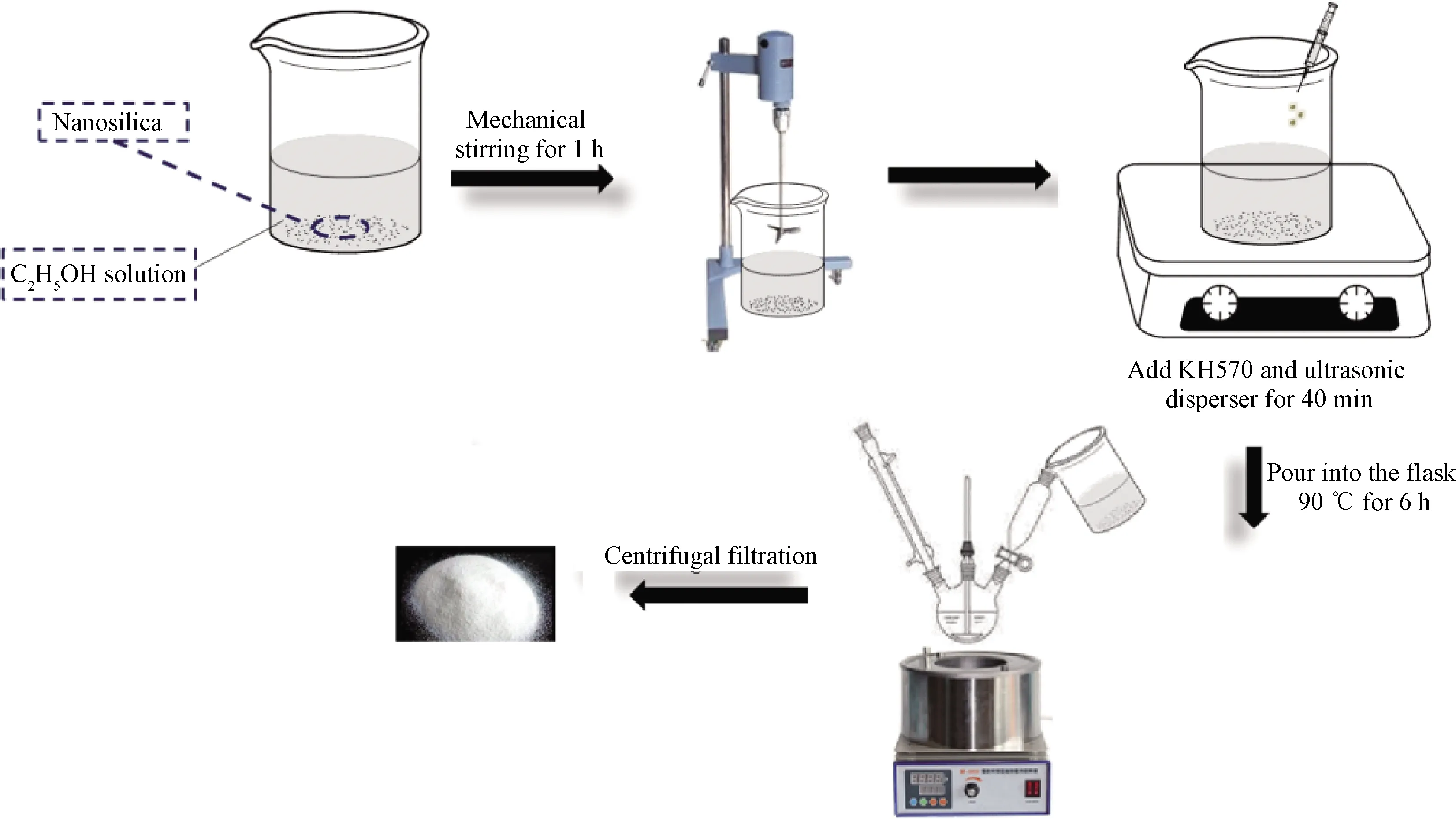
Fig.1 Flowchart of nano-oxide grafting modification
1.3 PIS and nanosilica modified epoxy resin
Modified epoxy resin with two components of polyimide and nanosilica were as follows.PIS with a weight fraction of 7.5% was dissolved in DMAc and then blended with desired amount of epoxy resin and curing agent.The mass ratio of epoxy resin and curing agent is 1.0∶0.8.The solution was stirred mechanically for 1 h and put into a vacuum oven at 60 ℃ to remove the solvent.High-speed mechanical stirring continued and nanosilica which was dissolved in ethanol was added in the stirring process.After stirring at a high speed for 4 h, the mixture was heated in a vacuum oven to remove the solvent.The mixture was then ultrasonically dispersed for 3 h so that the introduced particles were evenly dispersed in the resin.Finally, the degassed resin was poured into the preheated polytetrafluoroethylene(PTFE)mold and was cured.
1.4 Preparation of CFRPs
In this work, the CFRP was designed and prepared with a laminate number of 12, 16 and 20.It was set according to test standard ASTM D5528-13[25], where the specimen thickness was required to be 3, 4, 5 mm.Vacuum assisted resin transfer molding was not suitable for manufacturing the PIS/nanosilica modified CFRP.It was due to the fact that PIS and nanosilica particle in the epoxy resin were not able to flow through multiple laminates of fibers uniformly and hence resulted in poor overall particles dispersion.In the current work, to tackle this problem, the composite was prepared by pre-impregnation.The modified resin immersed the carbon fiber unidirectional fabric in advance so that the resin was fully infiltrated.A PTFE film was placed to prefabricate the cracks after laying 6 laminates of the soaked fabric on the mold.Then, another 6 laminates were laid.The CFRP was prepared by the vacuum resin transfer method.The same method was used to prepare 16-and 20-laminate CFRPs, as shown in Fig.2.
To this end one of you who is bold and artful must go into the city dressed as a traveller, and discover whom we have killed, and whether men talk of the strange manner of his death
1.5 Characterization
The tensile tests were conducted on an Instron 5967 tensile tester(Instron Ltd., America)according to ASTM D638-2014[26].The fracture toughness of epoxy resin matrix was conducted by the single edge notched 3-point bending(SENB)test through an Instron 5967 with the standard of ASTM D5045-2014[27].A scanning electron microscope(SEM,HITACHI S-4800, Hitachi, Japan)was used to observe the surface morphology of CFRP at an accelerating voltage of 3.0 kV.The size of specimens was 42 mm×10 mm×5 mm with the notch length from 4 mm to 6 mm.Fiber volume fraction of the composites prepared was(53.2±1.5)%.Five replicated samples were tested in all tests.The fracture toughness was studied by the critical stress intensity factorKICas
(1)
where

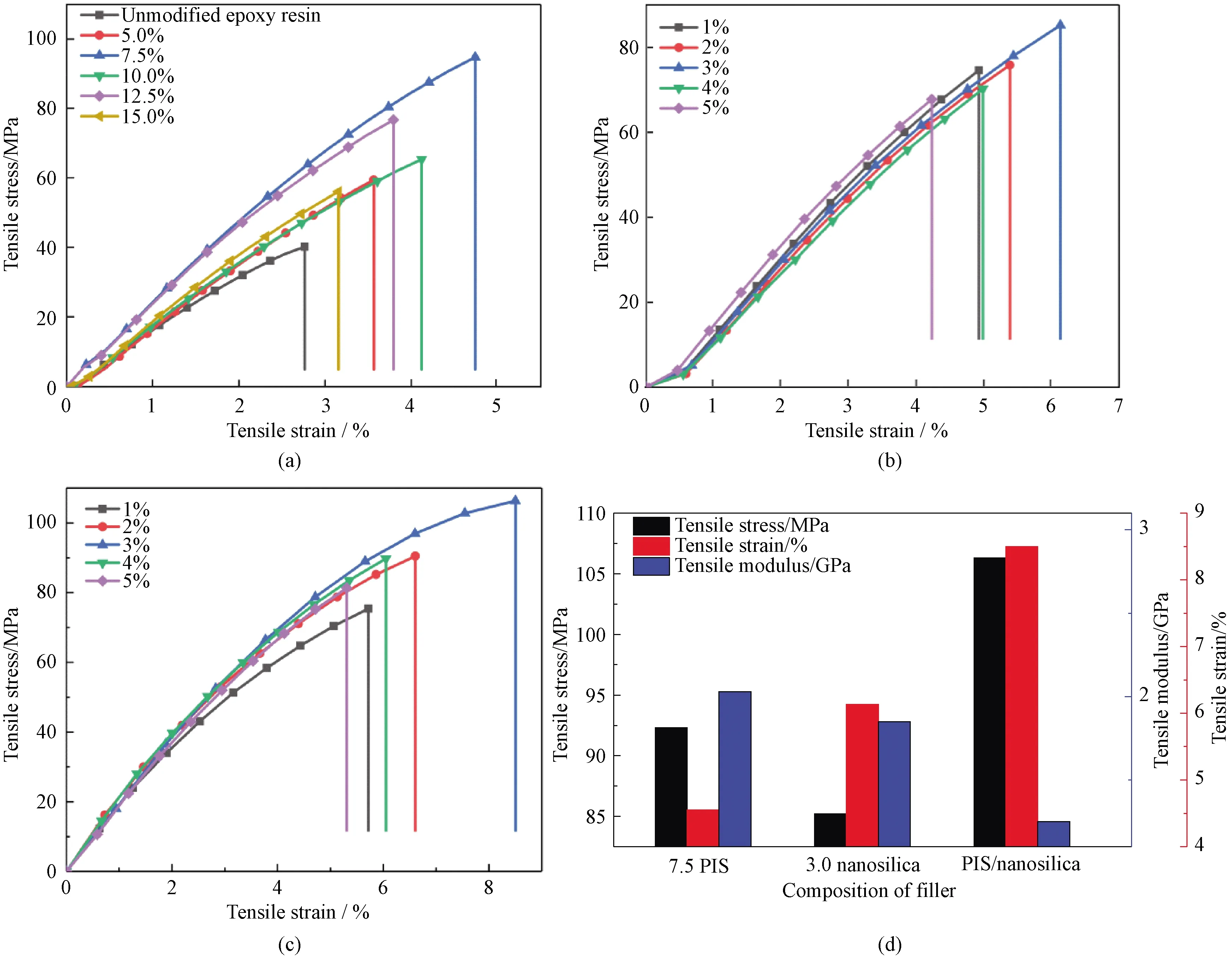
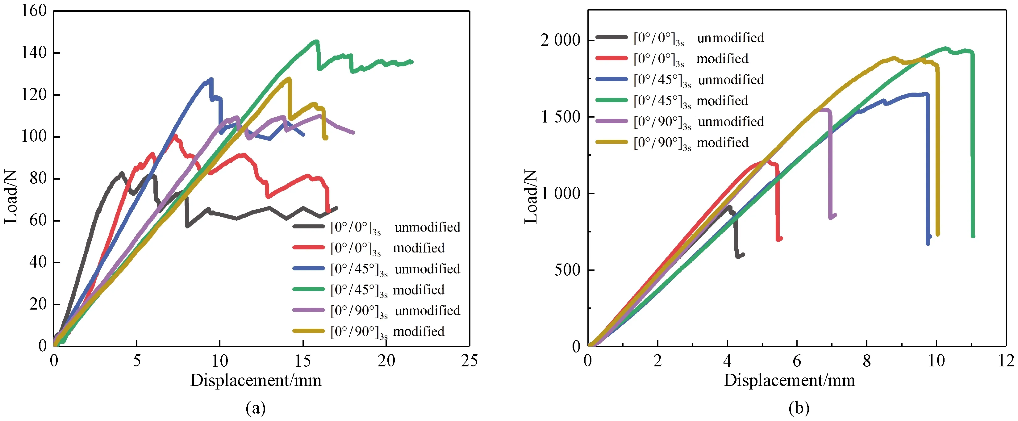
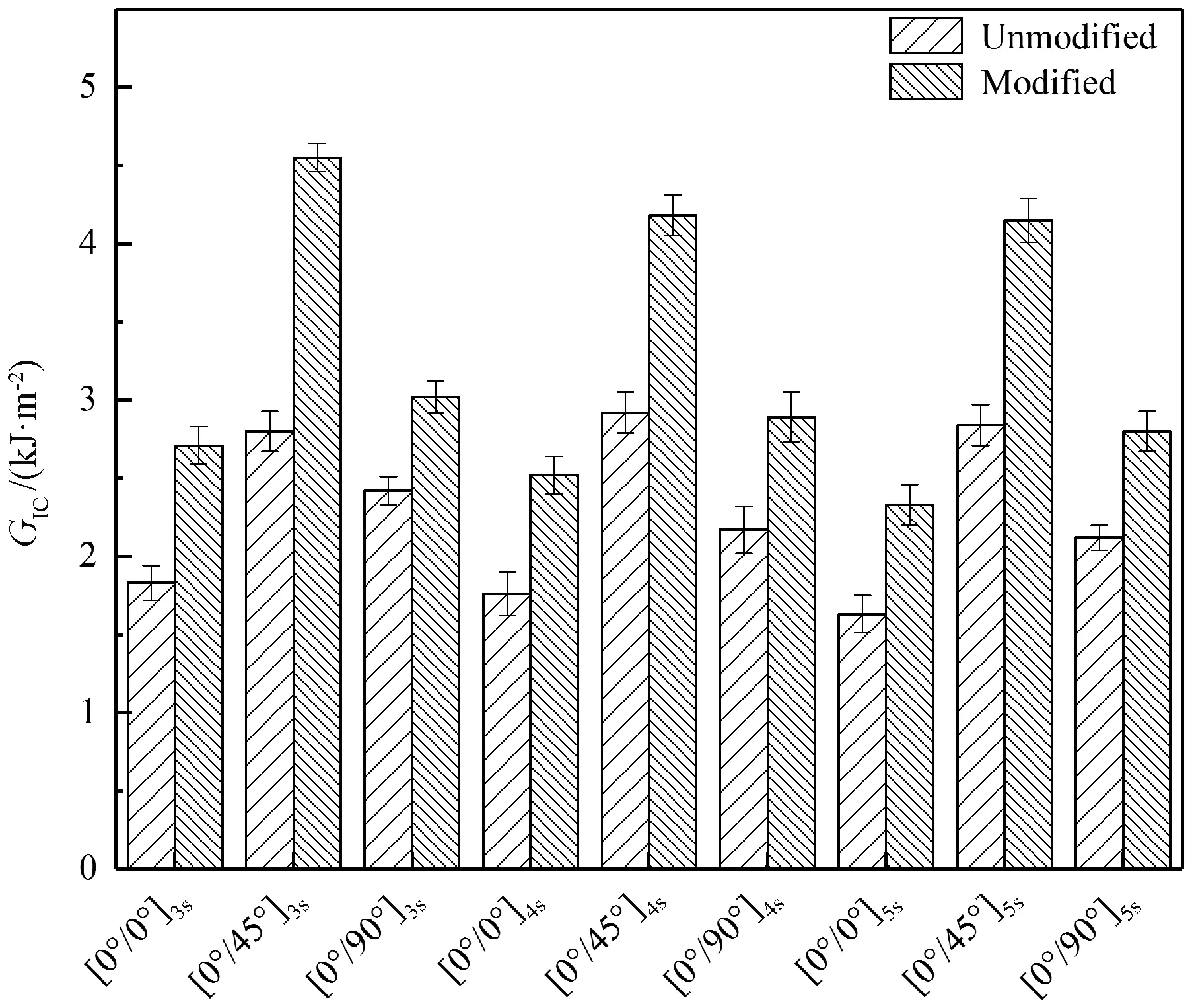
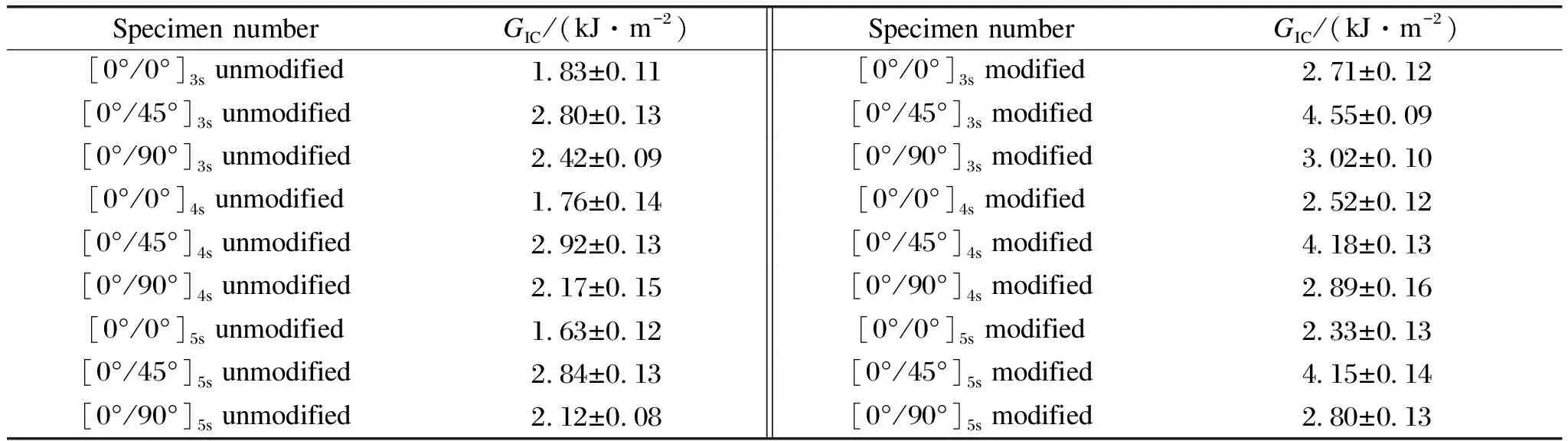
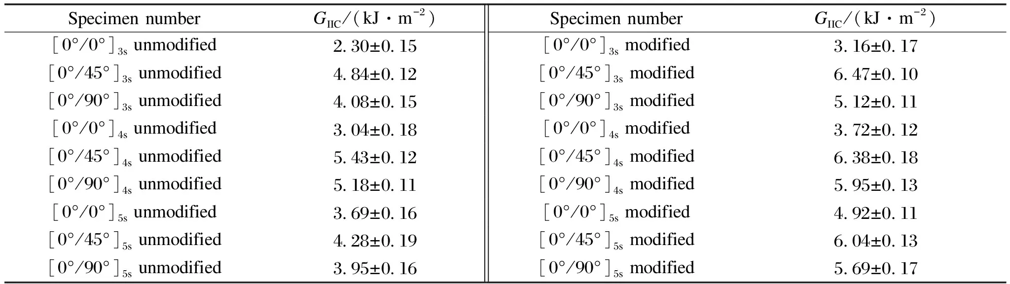
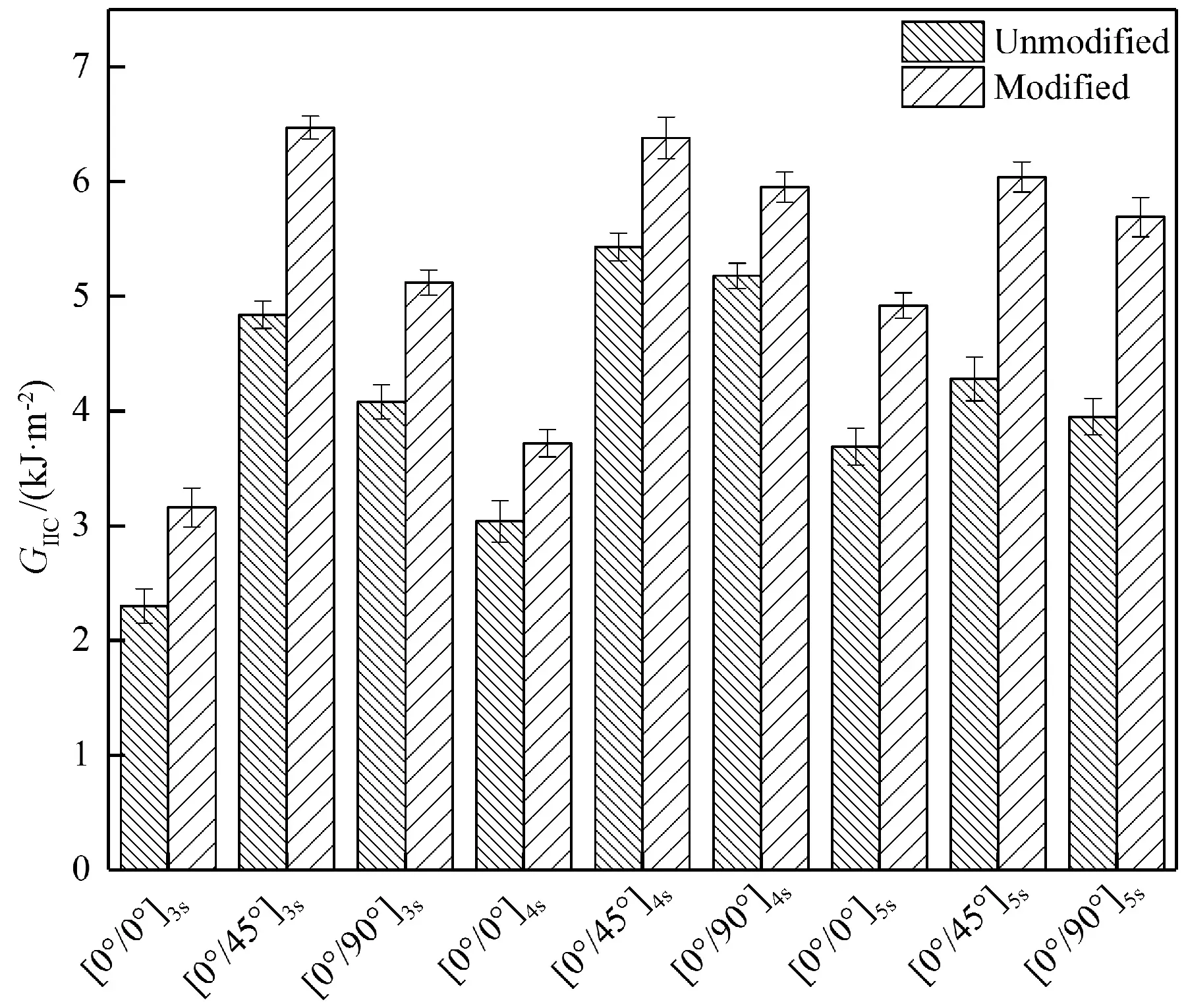
0 (2) PQis the fracture load,Bis the specimen thickness,Wis the specimen depth(width),xis a ratio andx=a/W(ais the crack length). This DCB test adopted test standard ASTM D5528-13[25].The length and width of the specimen are 180 mm and 20 mm, respectively.The specimen thickness is 3,4,5 mm, and the pre-crack length is 50 mm, as shown in Fig.3(a), wherelis the length of DCB.The test was carried out on the Instron 5967 universal material testing machine(Canton, Massachusetts, USA).The test tensile rate was 1 mm/min.The interlaminar strain energy release rateGICof DCB can be calculated by (3) wherePis the applied load,δis the displacement of the loading point,bis the width of the specimen,a0is the length of the pre-crack, and|Δ|is the correction amount of the delamination length. The ENF test adopts the test standard ASTM D7905-14[28].The specimen length and width of specimen are 120 mm and 20 mm, respectively.The thickness is 3,4,5 mm, and the pre-crack length is 45 mm, as shown in Fig.3(b), where 2Lis the length of span in ENF test.The test was carried out on the Instron 5967 universal material testing machine, and the test loading rate was 1 mm/min.ENF’s interlaminar strain energy release rateGIICcan be calculated by Fig.3 Experimental set up for DCB and ENF tests:(a)schematic diagram of DCB test;(b)schematic diagram of ENF test;(c)DCB test;(d)ENF test (4) The tensile stress, strain and modulus of modified epoxy resin are depicted in Fig.4.Figure 4(a)shows the stress-strain curve of PIS modified epoxy resin.It can be clearly seen that the fracture stress and strain of the modified resin are higher than those of the unmodified resin.With the increase of the content of polyimide, the failure stress first increased and then decreased, while the fracture strain remained the same trend.The PIS with a weight fraction of 7.5% showed the highest failure stress and strain.Compared with the unmodified resin, the fracture stress increased from 40.4 MPa to 92.3 MPa with an increase of 128%.The fracture strain increased from 2.67% to 4.55% with an increase of about 70%.Figure 4(b)presents the stress-strain curve of grafted nanosilica modified epoxy resin.The results showed that nanosilica improved the tensile strength and failure strain of epoxy resin.Compared with PIS, grafted nanosilica did not improve the fracture stress of the resin as well as PIS, but the fracture strain is higher than that of PIS.As shown in Fig.4(b), the epoxy resin modified by 3% nanosilica performed the best properties.The tensile strength increased from 40.4 MPa to 85.2 MPa, increased by 110.9%, and the fracture strain increased from 2.67% to 6.04% with an increase of 126.2%. Fig.4 Tensile stress, tensile strain and tensile modulus of modified epoxy resin:(a)PIS modified epoxy resin;(b)nanosilica modified epoxy resin;(c)PIS/nanosilica hybride modified epoxy resin;(d)comparison of the optimum modified components These two components can effectively improve the peak stress and failure strain of epoxy resin.The toughness effect was further investigated by mixing the two components in modified epoxy resin.The optimal component of PIS with a weight fraction of 7.5% was selected and blended with grafted nanosilica of different components to modify the epoxy resin.The results are shown in Fig.4(c).As expected, the PIS with a weight fraction of 7.5% and the grafted nanosilica blend with a weight fraction of 3.0% are the best combination, and the tensile stress reached 106.3 MPa, 163.1% higher than that of the unmodified resin.Tensile strain reached 8.5%, 218.4% higher than that of the unmodified resin.It was due to the synergistic effect between PIS and grafted nanosilica.The grafted active functional groups on nanosilica not only react with epoxy resin, but also form binding bonds with PIS.They are more closely combined and resist greater external forces and deformation. Fracture mechanics provides a quantitative analysis method for the fracture process of materials.It is based on the fact that fracture toughness is the force necessary for cracks to propagate through a structural part.Therefore,KICis used to measure the fracture toughness of the material.The fracture toughness values of epoxy resin modified in different ways are shown in Fig.5.As shown in Fig.5(a), it can be found that the fracture toughness of unmodified epoxy resin is low, suggesting a brittle material.With the introduction of PIS, the fracture toughness of modified epoxy resin is higher than that of the pure epoxy resin, and the fracture toughness value increases from 0.86 MPa·m1/2to 1.56 MPa·m1/2with the maximum increase of 81.4%.However, it then decreases quickly.This may be due to the fact that introduction of the PIS causes stress concentration and defects, resulting in a decline in the fracture toughness values of the material.Figure 5(b)shows the fracture toughness value of grafted nanosilica modified epoxy resin.The introduction of 1%-3% grafted nanosilica is beneficial to the fracture toughness of epoxy resin, although it is not as good as PIS.As the content of grafted nanosilica reached 5%, the fracture toughness value decreased significantly, approaching the unmodified epoxy resin.This indicated that the defects influenced the modified effect.The hazards are similar, and the toughening effect can not be achieved.KICof the mixed modification is shown in Fig.5(c).It could be clearly seen that the effect of the mixed modification was better than that of the single-component modification, andKICof the optimal component was more than twice than that of unmodified resin, exhibiting an excellent fracture toughness. Fig.5 Fracture toughness of modified epoxy resin:(a)PIS modified epoxy resin;(b)nanosilica modified epoxy resin;(c)PIS/nanosilica hybride modified epoxy resin Figure 6 shows the load-displacement curves of CFRP with different laying angles.It could be seen from Fig.6(a)that load increased linearly at the initial stage, and then the load decreased slightly.Load increased in a non-linear way and decreased after reaching the maximum load.Figure 6 shows the maximum load and the corresponding displacement of the composite material prepared by using the modified resin.The values were higher than those with the same ply angle, indicating that the binding force between the modified resin and the carbon fiber was stronger.The maximum load of the composite with an angle of 45° was higher than that of the composite with the angles of 0°and 90°.The composite carried greater external force in the loading process.The bond between fiber and resin was stronger resulting in highest fracture toughness.For the ENF test, as shown in Fig.6(b), all curves increased linearly in the initial phase, followed by a slight non-linear region before reaching the peak load.After the peak load, the initial cracks occurred and there was a sharp decrease of load.Similar to the test results of DCB, the maximum load and displacement of the composite with modified resin as the matrix were high.When the composite with an angle of 45° subjected to pressure load, the internal resin and carbon fiber dispersed the external force, exhibiting the best stress and strain. Fig.6 Load and displacement curves of composite materials with different lamination angles:(a)DCB test;(b)ENF test Figure 7 compares load-displacement curves of CFRP composites with different ply thicknesses.Figure 7(a)shows the mode I fracture curves of 12-, 16-and 20-laminate.Figure 7(b)illustrates 12-, 16-and 20-laminate of mode II fracture curves.It can be seen that the fracture load of CFRP presented a linear relationship with the specimen thickness.The displacement corresponding to the maximum load gradually decreased with the increase of the thickness.It was ascribe to that the stiffness of the specimen increased with the increase of the thickness.The mode I fracture curve was similar to that of the specimen behavior under the axial bending stress.The maximum load increased with the increase of thickness.The maximum load corresponding displacement decreased gradually.As could be seen from Fig.7, the load of 12-and 16-laminate composite slightly decreased first and then increased with increase in displacement before the maximum load.Catastrophic damage of composite occurred at the peak load.Followed by rapidly decrease in load.The failure pattern of 20-laminate composite is slightly different with 12-and 16-laminate composite materials.The greater thickness resulted in higher modulus and the maximum load.Load quickly erased when the specimen damaged.No platform was observed due to harder behavior and larger rigidity of CFRP specimens.The increase of specimen thickness led to the result that the maximum displacement decreased. Fig.7 Load-displacement curves of 12-, 16-and 20-laminate composites:(a)DCB test;(b)ENF test The effects of different ply thicknesses and ply angles on the fracture toughness of the composites were further studied.The mode I fracture toughness values of CFRP are shown in Fig.8 and Table 1.It can be clearly seen that the mode I fracture toughness of the composite modified resin with PIS and grafted nanosilica was significantly higher than that of the composite with unmodified resin as the matrix.For the CFRP with the same thickness, 45° laminate shows the best mode I fracture toughness without modification effect of resin.While 90° laminate takes the second place, and 0° laminate has the lowest mode I fracture toughness.It can be seen from Table 1 that the mode I fracture toughness of the composite with unmodified resin was between 1.72 kJ/m2and 2.92 kJ/m2.The laying angle of 45° shows the largest fracture toughness, which is about 70% higher than that of the 0° laminate.The fracture toughness of modified composite was between 2.33 kJ/m2and 4.55 kJ/m2.The maximum fracture toughness was at the 45° laminate, 95% higher than that at 0° laminate.After comparing mode I fracture toughness of the composites with different thicknesses, it is found that the thickness has little effect on mode I fracture toughness of the composites with the same laying angle and the same matrix.The results showed that the lay-up method had great influence on the fracture toughness of composite materials, which might be due to the fact that the lay-up method affected the maximum value of the bridge stress and the stress distribution in the bridge region.The 0° laminate ply occurred less bridging fibers during laminated expansion process and showed weak fiber bridging effect.The 45° composite plies produced more bridging fibers during the laminated expansion process, corresponding to fiber bridges and thus the synergy was strong.This caused bridge stress distribution in the fiber bridge area of the 45° ply to be higher than the bridge stress distribution in the fiber bridge area in the 0° ply. Fig.8 GIC of mode I fracture of CFRPs Mode II fracture toughness is also named as slip-open crack or shearing crack.The shear stress is parallel to the crack plane and perpendicular to the crack line, and the crack extends along the crack plane.As shown in Fig.9 and Table 2, the mode II fracture toughness of composite materials is presented.It can be seen from the figure that the change trend of fracture toughness of CFRP with different thicknesses and laying angles was consistent with that of mode I fracture toughness.The fracture toughness of the 45° angle laying mode was higher than that of the other angles, and the thickness exhibited little effect on the fracture toughness.The mode II fracture value of the composite with different thicknesses was basically constant. Table 1 GIC of mode I fracture of CFRPs Table 2 GIIC of mode II fracture of CFRPs Fig.9 GIIC of mode II fracture of CFRPs The typical macroscopic fracture morphology of mode I fracture and mode II fracture of composites are shown in Fig.10.As shown in Fig.10(a), mode I fracture test of the composite with a lay-up angle of 45° prepared with modified resin.It can be seen that fiber bridging occurred between sections when the composite was subjected to axial tensile failure.The bridging fiber increased the resistance of composite to external force.Higher fracture toughness was also observed.As shown in Fig.10(c), the macroscopic morphologies of mode I failure mode specimens laid at 0°, 45° and 90°, respectively.It can be seen that the section of CFRP composite laid at 0° was smooth, while the fracture of CFRP composite laid at 45° laminate was rough, resulting in plastic deformation.The fracture morphology of CFRP laid at 90° laminate was both smooth and rough fracture morphology.The mode II fracture test diagram of a composite prepared with modified resin is shown in Fig.10(b).From Fig.10(d), it can be found that the specimen with 0° angle of crack extension was smooth and with no block.At an angle of 45° to laying CFRP, a phenomenon that jumped a laminate in the crack was observed.The bridging fibers between cracks occurred in the adjacent laminate obstructed the crack propagation.It was owing to the rough fracture toughness.Although the CFRP laid at an angle of 90° also produced the stratification phenomenon during the crack propagation process, the bottom of specimen cracks affected the fracture toughness in the test. Fig.10 Failure morphology of composites:(a)mode I failure macroscopic diagram;(b)mode II failure macroscopic diagram;(c)mode I failure macroscopic diagram with different laying angles;(d)mode II failure macroscopic diagram with different laying angles The SEM images of mode I fracture toughness of the composite were analyzed to further investigate the toughness mechanism, as shown in Fig.11.In the mode I delamination expansion of the composite, fiber bridging and interlaminar matrix cracking were observed on the cross section.The strength of fiber bridging is closely related to the mechanical properties of the fiber/matrix interface.When the fiber/matrix interface strength is low, fiber bridging is more likely to be occurred during the delamination expansion process.At the same time, due to the appearance of bridging fiber, some cross-sectional characteristics were not directly related to the mode I crack propagation at the mode I delaminated propagation section.These features mainly were fiber bridging fracture and serrated sections in the local area of the matrix material.The SEM images of 0° composite laminate are presented in Figs.11(a)and 11(b).In Fig.11(a), the bond between carbon fiber and resin was not strong and the cross section was smooth for unmodified CFRP, leading to low fracture toughness value.The SEM images of modified composite are shown in Fig.11(b).Compared with Fig.11(a), the fracture section showed many jagged folds.The fiber and resin were tightly wrapped, so the composites could carry more loading to external forces.The cross-sections of the 45° laminate were presented in Figs.11(c)and 11(d).It can be found that the cross-section was overall smooth.Only few serrated structure was observed.As shown in Fig.11(d), the fracture surface was densely arranged with serrated sections.The resin adhered to the fiber surface tightly, showing a typical ductile fracture structure.A fairly high fracture toughness value was obtained.SEM images of the 90° laminate were observed in Figs.11(e)and 11(d).Similar to the 0° laminate, the cross-section of the unmodified composite was relatively smooth, while the cross-section of the modified composite presented a zigzag structure. Fig.11 SEM images of mode I fracture of CFRP:(a)unmodified resin at 0° laminate;(b)0° laminate of modified resin;(c)unmodified resin at 45° laminate;(d)modified resin at 45°laminate;(e)90° laminate of unmodified resin;(f)modified resin at 90° laminate Figure 12 shows the section morphology of mode II macroscopic crack propagation of the composite.The composite presents from left to right at 0°, 45° and 90°, respectively.The crack propagation of the 0° laminate was smooth and had no hindrance, while the 45° laminate underwent a jump in the laminated propagation path when the crack grew.The laminated propagation path jumped from the middle surface laminate of the DCB test piece.A large number of bridging fibers generated between adjacent laminates and cracks, which hindered the crack propagation.This may be the reason for the better fracture toughness of the specimen.For 90° laminate, a jump laminate phenomenon in the specimen appeared, and the bottom fracture of specimen affected its fracture toughness. SEM images of mode II section of the composite is shown in Fig.12.Compared with mode I fracture mode, the fracture section of mode II showed an obvious zigzag structure, which was a typical fracture feature of mode II fracture.Figures 12(a), 12(c)and 12(e)present the fracture sections of unmodified composites.The laying angles of the composites are 0°, 45° and 90°, respectively.Figures 12(b), 12(d)and 12(f)show the sectional views of the composite using PIS/nanosilica modified resin as the matrix.Fiber pulling-out and fiber debonding were observed in Figs.12(a), 12(c)and 12(e).It indicated that the bonding between epoxy resin and carbon fiber was poor, corresponding to low fracture toughness.As shown in Figs.12(b), 12(d)and 12(f), the fiber was closely bonded to the resin part and did not detach with the fiber in the loading process.This behavior led to resisting more deformation and exhibiting a higher fracture toughness. Fig.12 SEM images of mode II fracture of CFRP:(a)unmodified resin at 0° laminate;(b)0° laminate of modified resin;(c)unmodified resin at a 45° laminate;(d)modified resin at 45°laminate;(e)unmodified resin at 90° laminate;(f)modified resin at 90° laminate The fracture toughnesses of PIS and grafted nanosilica hybrid modified epoxy resin have been studied in this work.Mode I and mode II fracture toughnesses were used to evaluate the resin modification on toughness properties of composite laminates.Results showed that epoxy resin modified with PIS and graft nanosilica exhibited excellent strength and toughness.The tensile stress and strain were 163.1% and 218.4% higher than those of unmodified resin, respectively.TheKICvalues of epoxy resin increased from 0.86 MPa·m1/2to 1.98 MPa·m1/2, indicating great enhancement in toughness.The mode I and mode II fracture toughnesses of CFRP were improved through epoxy modification.Compared with unmodified resin(GIC, 1.63-2.92 kJ/m2),GICof composite specimens increased from 2.33 kJ/m2to 4.55 kJ/m2, and the variation trend ofGIICwas consistent with that ofGIC.In addition, the thickness had no effect on the fracture toughness of composites.The SEM images further indicated that the lamination method had an effect on the fracture toughness of the composite, and 45° laying angle showed the highest fracture toughness.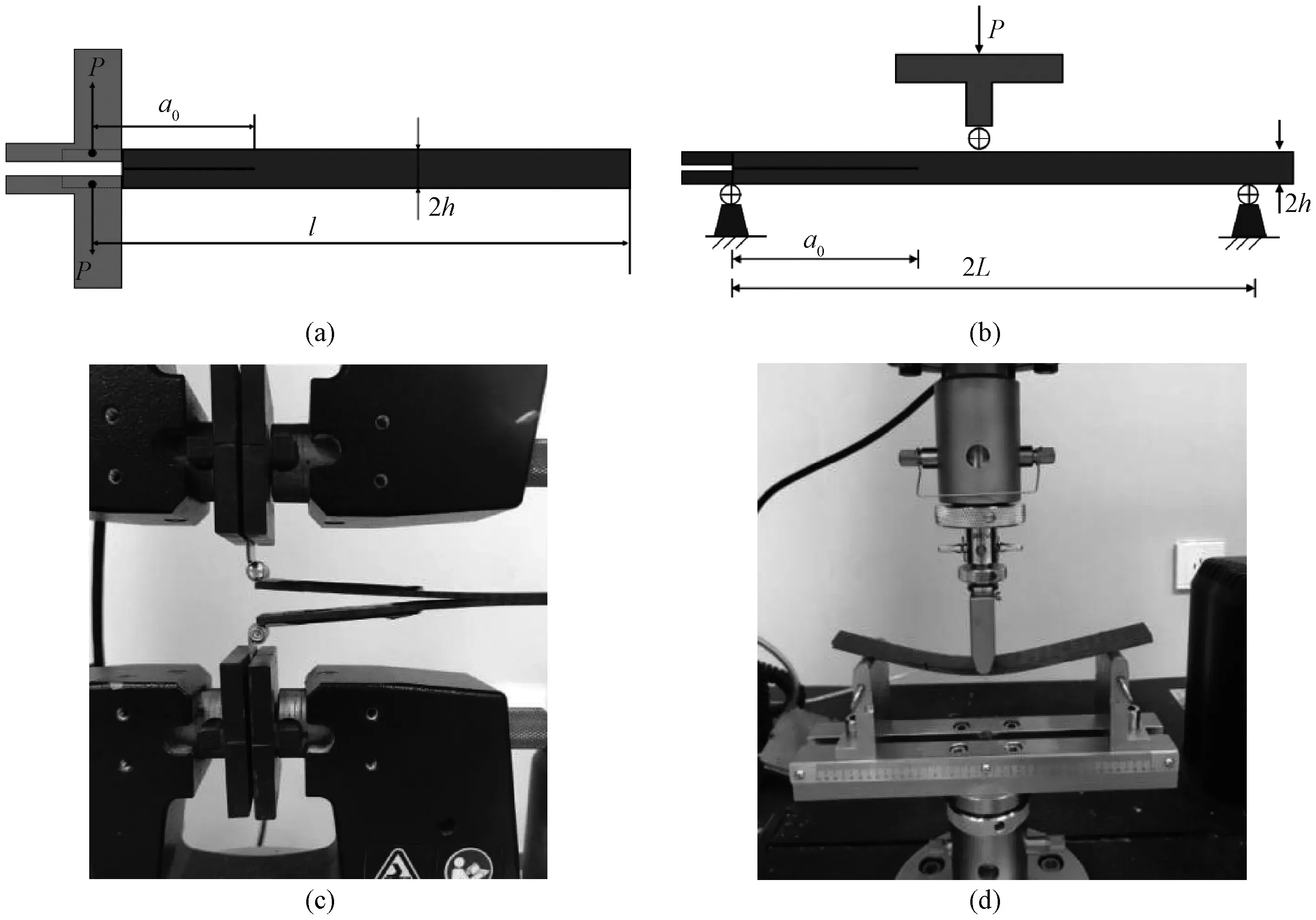
2 Results and Discussion
2.1 Tensile and fracture properties of hybride modification epoxy

2.2 Mode I and mode II interlaminar fracture toughness

2.3 Mode I and mode II interlaminar fracture toughness
2.4 Failure morphology analysis


3 Conclusions
杂志排行

Journal of Donghua University(English Edition)的其它文章
- Three-Dimensional Model Reconstruction of Nonwovens from Multi-Focus Images
- Three-Dimensional Metacomposite Based on Different Ferromagnetic Microwire Spacing for Electromagnetic Shielding
- Blockchain-Based Architectural Framework for Vertical Federated Learning
- Optimal Control of Heterogeneous-Susceptible-Exposed-Infectious-Recovered-Susceptible Malware Propagation Model in Heterogeneous Degree-Based Wireless Sensor Networks
- Enhanced Arsenite Removal Using Bifunctional Electroactive Filter Hybridized with La(OH)3
- Students’ Feedback on Integrating Engineering Practice Cases into Lecture Task in Course of Built Environment