A 32-channel 100 GHz wavelength division multiplexer by interleaving two silicon arrayed waveguide gratings∗
2021-12-22ChangjianXie解长健XihuaZou邹喜华FangZou邹放LianshanYan闫连山WeiPan潘炜andYongZhang张永
Changjian Xie(解长健) Xihua Zou(邹喜华) Fang Zou(邹放)Lianshan Yan(闫连山) Wei Pan(潘炜) and Yong Zhang(张永)
1Center for Information Photonics and Communications,School of Information Science and Technology,Southwest Jiaotong University,Chengdu 611756,China
2State Key Laboratory of Advanced Optical Communication Systems and Networks,Department of Electronic Engineering,Shanghai Jiao Tong University,Shanghai 200240,China
Keywords: wavelength division multiplexer, arrayed waveguide grating, silicon photonics, Mach–Zehnder interferometer
1. Introduction
With the development of communication networks,wavelength division multiplexer has become a crucial device due to its role in expanding the channel capacity. The passive wavelength multiplexers in optical transmission system mainly include microring resonator (MRR),[1,2]Mach–Zehnder interferometer (MZI)[3,4]and arrayed waveguide grating (AWG).[5–7]Since the AWG was proposed by Smit in 1988,it has been extensively studied due to its compactness compared to that of MRR and MZI, and it also has lower insertion loss and better crosstalk performance.[8,9]Specifically,a 16-channel AWG based on silicon nitride was proposed in Ref.[10],which achieved−30 dB adjacent channel crosstalk with 0.5 dB loss. But the footprint of the entire device exceeded 1 cm2due to the low refractive index difference. A compact AWG was designed based on the high refractive index contrast characteristics of silicon,[11]whose footprint was about 400×600µm2. However,the adjacent channel crosstalk was only 10 dB. Moreover, some novel designs such as fold structure were also proposed. For example, add reflectors at the arrayed waveguide to form a 4-channel folded AWG,[12]the crosstalk and insertion loss are about−20 dB and 3.5 dB,respectively. Therefore,it is still a challenge to realize multichannel high performance AWG in compact footprint.
In this paper, a 32-channel wavelength division multiplexer is designed by cascading two parallel 16-channel AWGs and an MZI.The channel spacing of 16-channel AWG and FSR of MZI are both 200 GHz. The output spectra of the two AWGs are interleaved and aligned with MZI. Thus,a 32 channels,100 GHz channel spacing wavelength division multiplexer is realized.
2. Design of 32-channel wavelength division multiplexer
Figure 1 shows the structure of the wavelength interleaved wavelength division multiplexer which is composed of an MZI and two on-chip AWGs. One AWG mainly includes input and output waveguides, two slab waveguides and arrayed waveguides. The arrayed waveguides are a group of strip waveguides with fixed length difference. The incident light is dispersed and output to the arrayed waveguides with equal amplitude and phase distribution in the first slab waveguide. As the length of the arrayed waveguide increases linearly,the phase change caused by the wavelength change linearly changes along the output aperture.As a result,the light is tilted and the focus moves along the output surface of the second slab waveguide. By placing the output waveguide in an appropriate position, the spatial separation of different wavelength channels can be obtained.
The parameters of AWG should follow the constraint[13]
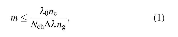
wheremis the order of the phased array,λ0is the central wavelength,ncandngare the effective refractive index and the group index of the arrayed waveguides, ∆λis the channel spacing of the AWG,andNchis the output number of the AWG.In our design,the parameters are specified asNch=16,∆λ=1.6 nm, andλ0=1.55 µm. The width of the arrayed waveguide is 500 nm, and the input mode is the fundamental transverse electric(TE0)mode. With these parameters and SiO2cover layer,nc=2.446 andng=4.053 are derived. According to Eq.(1), theRof the slab waveguide can be calculated by
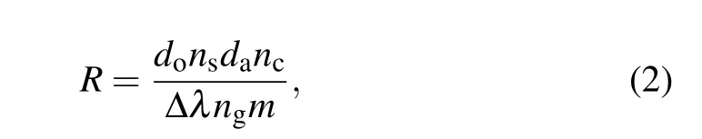
wheredo=2 is the output waveguide spacing,da=2 is the arrayed waveguide spacing,andns=2.848 is the effective refractive index of the slab waveguide. Figure 2 shows the numerical simulation result obtained by IPKISS 3.5.0 with these parameters. It can be seen that the adjacent crosstalk,which is defined as a power leakage from a neighboring channel,[14]is lower than−50 dB.
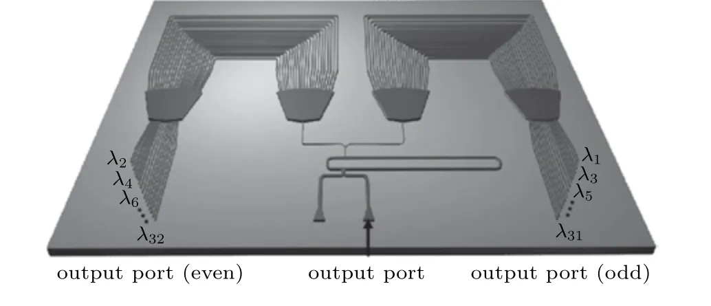
Fig.1. Schematic diagram of the interleaved wavelength division multiplexer.
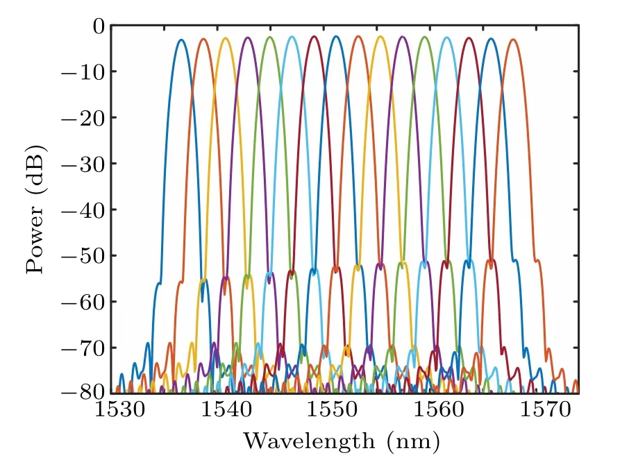
Fig.2. Numerical results of silicon 16-channel AWG.
In order to implement a 32-channel wavelength division multiplexer, we mark the outputs of AWG#1 and that of AWG#2 as odd channels and even channels, respectively.[15]For this purpose, we set the central wavelength of AWG#2 asλ0=1550.8 nm. Meanwhile, we keep themand ∆Lunchanged. Under these conditions, the center wavelength of AWG will shift when the effective refractive index of the arrayed waveguide changes. This wavelength shift can be calculated by
Changing the width of the arrayed waveguide is a flexible way to achieve wavelength shift, while an MZI is cascaded with two AWGs. As above analyzed, the FSR of this MZI is 200 GHz and it can be calculated by[16]
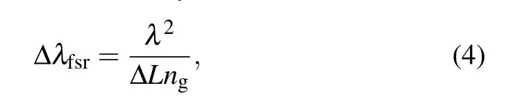
where ∆Lis the arm length difference of MZI andng=4.053 is the group index of the arm waveguide. When ∆λfsr=1.6 nm, we can calculate ∆L ≈370 µm. The MZI is formed by double cascaded MMIs. In order to reduce the loss introduced by MZI,the width of MMI iswMMI=3.6µm and the position of the port is atx=±wMMI/6. With this condition,we analyze the transmission responses of MMI under different lengths. The structure of MMI and analyze results are shown in Fig.3.
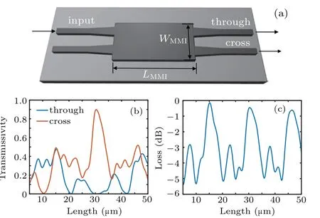
Fig.3.(a)The structure of MMI for designing MZI;(b)transmissivities of the two output ports for MMI with different lengths;(c)total loss of output ports for MMI with different lengths.
When the length of MMI isLMMI=15 µm, the output powers of the two output-ports are both close to 50%and the total loss is minimized. In addition,we also analyze the transmission responses of the two output ports within the bandwidth of 1500 nm–1600 nm,the results are shown in Fig.4(a).Based on the above optimization parameters, two MMIs are cascaded to form an MZI.Figure 4(b)shows its transmission response and it can be found that the insertion loss is less than 0.7 dB within the bandwidth of 40 nm.
When the MZI is cascade with AWG, the wavelength should be aligned between two sections through the thermal tuning embedded in the MZI part. Thermal tuning is achieved by heating the waveguide to change its effective refractive index. Therefore, the different heating powers are applied to tungsten to adjust the waveguide refractive index. It can be seen from Fig. 5(a) that ∆neffis proportional to the heating power.
In addition, we also simulate the wavelength drift of MZI under different heating powers. The result is shown in Fig.5(b). It can be seen that the wavelength shifts with changing the heating power.

Fig.4. (a)Transmission responses of through and cross ports of MMI.(b)Transmission responses of MZI.

Fig.5. (a)Waveguide refractive index under different heating powers;(b)wavelength drifts of MZI with different heating powers.
The output of this wavelength division multiplexer is obtained by numerical simulation and shown in Fig. 6. It can be found that the insertion loss and the crosstalk are less than 3.6 dB and−27 dB,respectively.

Fig.6. Numerical result of 32-channel wavelength division multiplexer.
3. Fabrication and tests
In order to verify the proposed design, a composed 32-channel multiplexer is fabricated by E-beam lithography.AWG#1 and AWG#2 are fabricated with different waveguide widths of 495 nm and 490 nm, respectively. Figure 7 shows the experimental setup.
The scanning electron microscope (SEM) images are shown in Fig. 8(a). Thanks to the waveguide width difference, a distinction in the effective refractive index is introduced between AWG#1 and AWG#2, resulting in a required wavelength shift for the interleaving structure. The insertion loss and crosstalk of the two AWGs are lower than 5 dB and−15 dB,respectively,as shown in Figs.8(b)and 8(c).
After adjusting the FSR of MZI to 200 GHz,the transmission responses of MZI and 32 interleaved channels are measured and shown in Fig.9. It is clear that that the crosstalk is lower than−15 dB.
A comparison between this work and previous 16-channel AWGs is listed in Table 1. The footprint of our work is more compact than that of nitride AWG,even though more channels are realized in this proposed design. In addition, a comprehensive performance comparison between the fabricated 32-channel wavelength division multiplexer and other AWGs previously reported is listed in Table 1. Our device provides 32 available wavelength channels for the first time,and excellent specifications on crosstalk and dense wavelength spacing.

Fig.7.The experimental setup for 32-channel wavelength division multiplexer.
Fig.8. (a)Microscope images of AWG.Transmission responses of the(b)AWG#1 and(c)AWG#2.
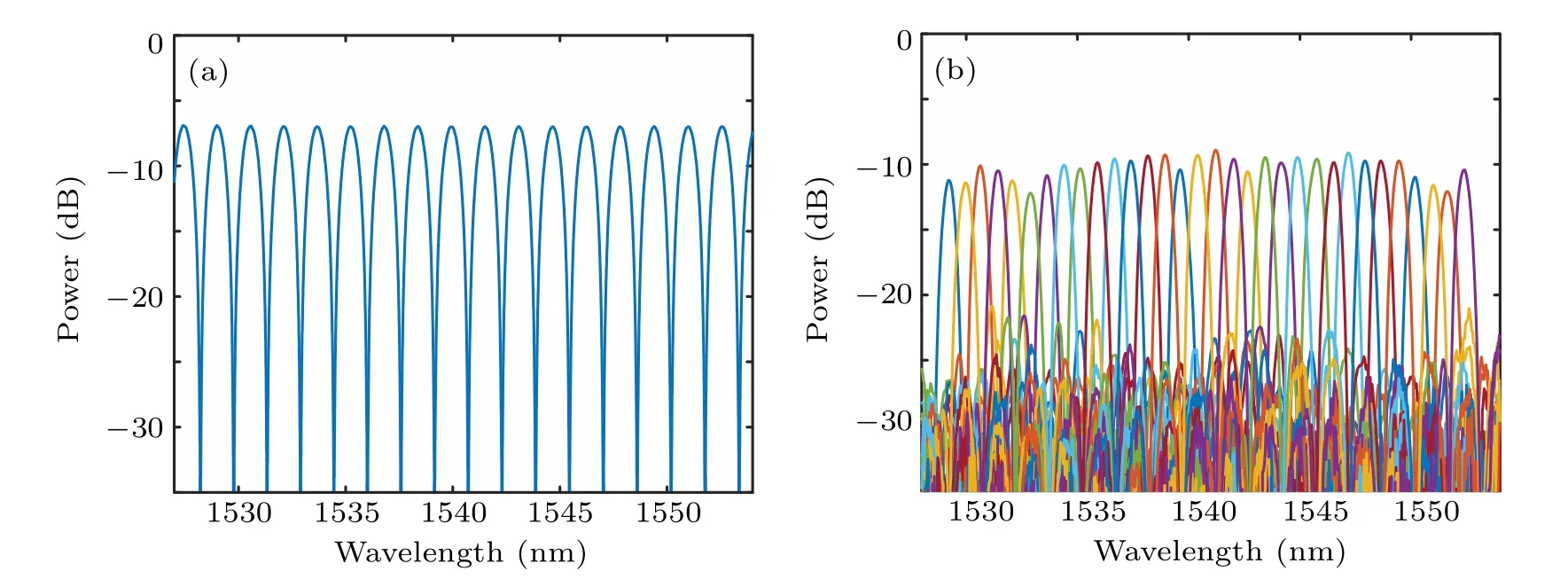
Fig.9. (a)Transmission response of tunable MZI.(b)Transmission response of the 1×32-channel interleaved wavelength division multiplexer.
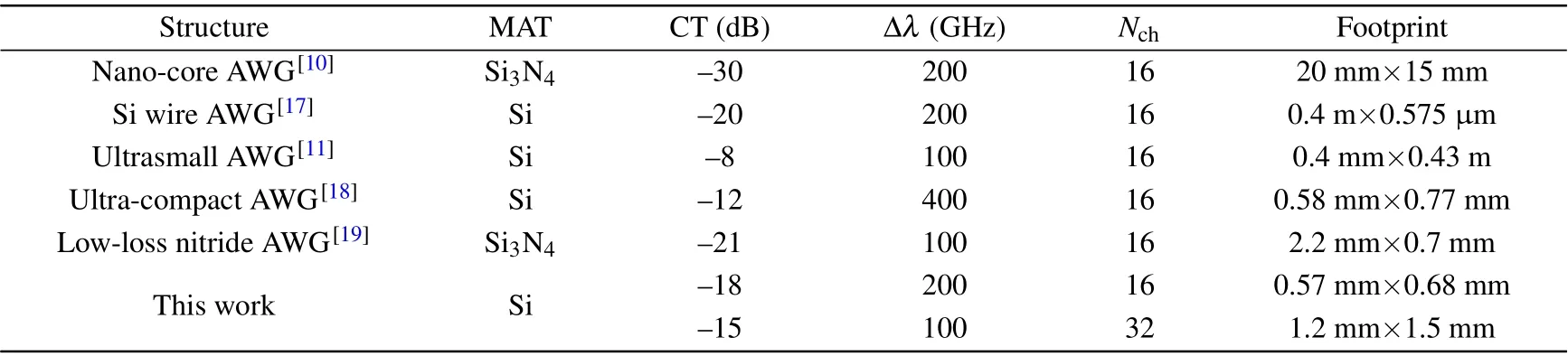
Table 1. Performance comparison of 16-channel AWG based wavelength division multiplexers.
4. Conclusion
We have designed a 32-channel wavelength division multiplexer with the channel spacing of 100 GHz. This device is fabricated with two wavelength interleaved AWGs and a tunable MZI,using E-beam lithography.Experiment results show that the crosstalk is lower than−15 dB for the 32 100-GHz channels. Such silicon wavelength division multiplexer with dense spacing and large channel capacity will find important applications in optic commutations,microwave photonics,and optical sensing.
猜你喜欢
杂志排行

Chinese Physics B的其它文章
- Transient transition behaviors of fractional-order simplest chaotic circuit with bi-stable locally-active memristor and its ARM-based implementation
- Modeling and dynamics of double Hindmarsh–Rose neuron with memristor-based magnetic coupling and time delay∗
- Cascade discrete memristive maps for enhancing chaos∗
- A review on the design of ternary logic circuits∗
- Extended phase diagram of La1−xCaxMnO3 by interfacial engineering∗
- A double quantum dot defined by top gates in a single crystalline InSb nanosheet∗