Research on corona discharge suppression of high-voltage direct-current transmission lines based on dielectric-film-covered conductor
2021-02-27YuzeJIANG姜雨泽QiyingLI李其莹XuekaiZHANG张学凯DiwenJIANG姜迪文ShiqiangLIU刘士强BangfaPENG彭邦发andJieLI李杰
Yuze JIANG (姜雨泽), Qiying LI (李其莹), Xuekai ZHANG (张学凯),Diwen JIANG(姜迪文),Shiqiang LIU(刘士强),Bangfa PENG(彭邦发) and Jie LI (李杰),∗
1 State Grid Shandong Electric Power Research Institute, Jinan 250003, People’s Republic of China
2 State Grid Shandong Electric Power Company, Jinan 250001, People’s Republic of China
3 State Grid Jinan Jiyang Power Supply Company, Jiyang 251400, People’s Republic of China
4 School of Electrical Engineering,Dalian University of Technology,Dalian 116024,People’s Republic of China
Abstract Corona discharge suppression for high-voltage direct-current (HVDC) transmission lines at line terminals such as converter stations is a subject that requires attention.In this paper,a method based on a conductor covered with dielectric film is proposed and implemented through a bench-scale setup.Compared with the bare conductor,the corona discharge suppression effect of the dielectricfilm-covered conductor under positive polarity is studied from the composite field strength and ion current density using a line-plate experimental device.The influences of film thickness and film material on the corona discharge suppression effect are investigated.The charge accumulation and dissipation characteristics of different film materials are also studied.The results show that the conductor covered with dielectric film has excellent ability to inhibit corona discharge.The groundlevel composite field strength of the conductor covered with dielectric film is lower than its nominal field strength,and its ion current density is at the nA m−2 level.The corona threshold voltage can be promoted by increasing the film thickness,but the ability to inhibit corona discharge becomes weak.The larger the surface electric field strength,the more charge accumulated,but the faster the charge dissipation rate.Compared with polyvinyl chloride film,cross-linked polyethylene film has stronger charge accumulation ability and slower charge dissipation rate,which can better restrain the corona discharge of HVDC transmission lines.
Keywords: high-voltage direct-current (HVDC) transmission lines, corona discharge suppression, dielectric-film-covered conductor, composite field strength, ion current density
1.Introduction
Although corona discharge is widely used in dust removal,sterilization, pollutant degradation and other applications [1–3],corona discharge of high-voltage direct-current (HVDC) transmission lines can cause a series of electromagnetic environment problems such as corona loss, radio interference and audible noise [4–6].In addition, after corona discharge, the directional movement of space charge generated under the action of an electric field forms an ion flow field[7].Under the action of an electric field, heteropolar charged suspended particles adhere to the surface of the conductor,which makes the corona discharge more serious.The charged suspended particles of the same polarity continuously accumulate on the power equipment under the lines,which seriously endangers the safety of the equipment and greatly increases the maintenance cost [8, 9].It should be noted that the inhibition of this phenomenon needs to be paid more attention in the case of a wire terminal(such as a converter station).On one hand,in this situation the height of the HVDC wire declines visibly, which can enhance the corona discharge intensity.On the other hand, usually in these stations there are many items of power equipment that can be influenced by the strong corona discharge.Therefore, it is necessary to study and suppress the corona discharge of HVDC transmission lines.
In recent years,scholars have carried out a lot of theoretical and experimental studies on the corona discharge and electromagnetic environment of HVDC transmission lines[10–12].Cuiet alsummarized the research status of ion flow fields at home and abroad in detail[13].Bianet alstudied the influence of fine particulate matter on the variation of surface morphologies of conductors subjected to positive DC voltages,and found that the interactions between particles play a critical role in the formation of agglomerations and parallel chains[14].Liuet alfocused on the edge effect of an ion current density plate on the measured results under HVDC.The results show that the edge effect can be basically eliminated when the width of the protective annulus is less than 2 mm [15].Based on a reduced-scale corona cage,Zhanget alconducted a theoretical study on radio interference of HVDC transmission lines [16].Liuet alstudied the correlation between audible noise and the corona current spectrum of HVDC transmission lines [17].Based on the plasma chemical model,Chenet alnumerically simulated the Trichel pulse in the early stage of negative DC corona discharge[18].Zhuet alused an accelerating contamination depositing apparatus to study the effect of pollutants on the corona discharge of conductors[19].It was found that the corona discharge could be weakened when the charged particles were uniformly accumulated on the conductor surface,while the non-uniform pollution on the conductor led to the deterioration of corona discharge.The current research mainly focuses on the electromagnetic environment measurement and simulation calculation after corona discharge.However, the source of the electromagnetic environment of HVDC transmission lines is corona discharge.In order to weaken or even eliminate the electromagnetic environment problems as much as possible, it is of great practical significance and academic value to study the methods of suppressing corona discharge.At present,in order to inhibit corona discharge,methods of increasing the conductor diameter, increasing the number of splits or optimizing the tower heights and distances between poles are usually adopted.Although these methods can suppress corona discharge to some extent, they cannot eliminate it fundamentally.
In this paper, a new method of inhibiting corona discharge of HVDC transmission lines based on the suppression effect of a conductor covered with dielectric film is proposed.In sections 2.1 and 2.2,the line-plate experimental device and the principle of corona discharge suppression by a conductor covered with dielectric film are introduced, respectively.In section 3.1, the composite field strength and ion current density distribution of a bare conductor and a conductor covered with dielectric film are compared, and the effectiveness of corona discharge suppression is verified.The effects of film thickness and film material on corona discharge suppression are studied in section 3.2.In section 3.3, the influence of film material on the surface charge accumulation and dissipation characteristic is explored.Finally, the main conclusions are given in section 4.
2.Line-plate experimental device and corona discharge suppression principle
2.1.Line-plate experimental device
Figure 1 shows the schematic diagram of a monopolar line-plate corona discharge experimental device.The device mainly consists of four parts: a high-voltage conductor, grounded plate,composite field strength measurement area and ion current density measurement area.The length of the high-voltage conductor is 2000 mm, it is composed of a bare aluminum conductor or an aluminum conductor covered with dielectric film,and its ends are fixed by nylon insulation brackets.In order to prevent tip discharge of the conductor,shielding balls with radii of 20 mm are installed at both ends of the conductor.The size of the grounded plate is 3000 mm×2000 mm,and it is composed of an internal measuring plate and external shielding plate.The outer shield plate is 250 mm in width and its purpose is to eliminate the influence of the edge effect on internal measurement.The two grounded plates are separated by an air gap of 1 mm.The composite field strength measurement part consists of nine circular holes with diameters of 90 mm in the front,numbered from E1 to E9.The field intensity distribution on the ground level is measured by a DC field strength meter.The ion current density measurement part consists of seven ion current density plates at the rear, numbered from I1 to I7.The ion current density distribution on the ground level is measured by a sampling resistance method.The sample resistance is 10 MΩ.The size of the ion current density plate is 158 mm×218 mm,and has four chamfers with radii of 10 mm.The ion current density plate is flush with the internal measuring plate and there is an air gap of 1 mm between them.In order to facilitate the comparison of experimental results, the height of the line-plate was maintained at 500 mm.
Polyethylene insulation materials are widely used in high-voltage transmission and distribution fields because of their excellent insulation performance and anti-breakdown properties [20, 21].In this work, two typical insulating materials, cross-linked polyethylene (XLPE) and polyvinyl chloride (PVC) are studied.The specifications of the conductors used in the experiment are shown in table 1, whered,randRrepresent the diameter of the bare conductor and the inner and outer diameters of the conductor covered with dielectric film, respectively.
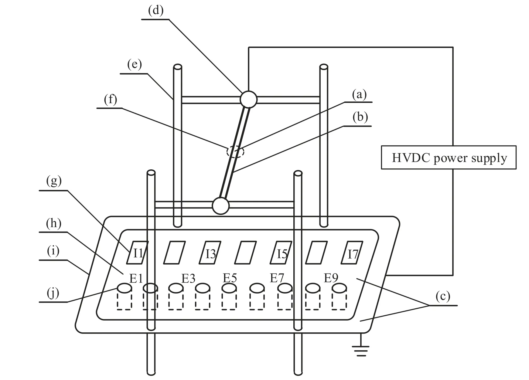
Figure 1.Schematic diagram of line-plate experimental device.(a) Bare conductor, (b) film material, (c) grounded plate, (d) shielding ball,(e)nylon bracket,(f)conductor covered with dielectric film,(g)ion current density plate,(h)internal measuring plate,(i)external shielding plate, and (j) DC field strength meter.

Table 1.Specifications of conductors used in the experiment.
Based on the LabVIEW platform, the programmable function of power supply is used to control the voltage change ranging from 0 kV to 100 kV with a rising rate of 10 kV min−1.An NI-USB-6210 data acquisition card is used to collect the ground-level field strength and ion current density value.The sampling rate is 10 K s−1and the sampling time is 1 min.The ion current density is obtained by recording the voltage of the acquisition resistance through a data acquisition card.The ion current density data are collected for 1 min at a time, totaling 600 data values.Each scatter in figures 5,6,9,10 and 13 is the average value of 600 data values.The synthetic field intensity is measured by a field grinding instrument.Since the synthetic field intensity is stable and the field grinding instrument is accurate,these data are the result of a single measurement.The experiments are carried out in atmospheric-pressure air with the temperature varying from 18.5 °C to 21.6 °C and the relative humidity ranging from 31% to 42%.Moreover, in order to eliminate the influence of pollutants on the surface of conductors, absolute ethanol is used to clean the conductors before the experiments.
The thermal performance of the covered conductor is an important factor that also needs to be considered during the method implementation.Firstly,compared with AC transmission lines,the heat generated by the core layer inside DC transmission line is lower, because DC transmission lines do not have to consider the heat generated by the core layer due to the skin effect.Secondly, for the dielectric-film-covered conductor to inhibit corona discharge,it is different from a typical cable section possessing multi-layer insulation material composition.The dielectric film thickness is smaller than the typical cable thickness;in other words,the intermediate polymer can conduct heat faster in this situation.Thirdly, in contrast to submarine cables or underground cables,this work is aimed at covering dielectric film on overhead lines; due to the influence of air convection in the outer surface of the insulation medium,heat dissipation there can be faster.In general,considering the three aspects of internal core heat generation, intermediate polymer heat conduction and surface layer heat dissipation,the impact of the core heat generation is not large in the formal implementation.
2.2.Principle of corona discharge suppression by dielectric film

Figure 2.Schematic diagram of the corona discharge suppression effect of a conductor covered with dielectric film under positive polarity.(a) Initial stage of corona discharge and (b) later stage of corona discharge.
Figure 2 shows a schematic diagram of corona discharge suppression by the suppression effect of a conductor covered with dielectric film under positive polarity.The conductor covered with dielectric film is composed of an internal metal conductor and external insulating dielectric.After the discharge, under the action of an electric field, electrons continuously accumulate on the surface of the insulating dielectric and generate an opposite electric field, while space positive ions move away from the conductor until they move to the ground level (as shown in figure 2(a)).The superposition of the electric field generated by the charge accumulation on the dielectric surface and the nominal field strength weaken the composite electric field in the outer space.The continuous accumulation of electrons makes the space composite field strength gradually decrease.When the electric field around the conductor drops to the threshold voltage, the corona discharge stops (figure 2(b)) and the ion current disappears, so as to achieve the purpose of suppressing corona discharge.
It is assumed that the surface of the conductor is equipotential and the ground remains at zero potential, and the effect of the dielectric constant of the material on the external electric field of the material is not considered.Without considering the accumulation of heterogeneous charges on the surface of the medium, the electric field intensity on the surface of the conductor can be written as equation (1)according to the Gauss theorem and mirror image theory[22]:
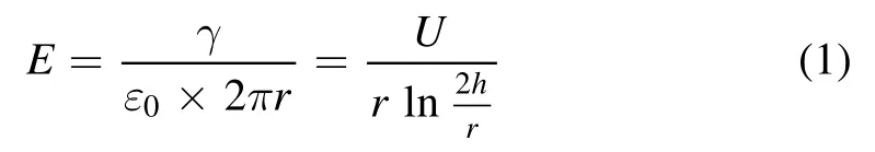
whereEis the surface electric field strength of the conductor(if it is a coated conductor,it is the outer electric field strength of the film), kV cm−1;Uis the conductor potential, kV;ris the radius of the conductor(if it is a film-covered conductor,it is the overall radius of the film-covered conductor), cm;his the height of the conductor from the ground, cm;ε0is the vacuum dielectric constant ε0= 8.85×10⁻¹⁴F cm−1;and γ is the linear charge density of the central conductor,kC cm−1.
The internationally recognized formula for a coronagenerating electric field is the Peek formula; the AC Peek formula can be converted into DC form as follows:

whereEonis the initiation field intensity of the corona discharge, kV cm−1;mis the roughness coefficient of the conductor surface;and δ is the relative density of air,Under standard atmospheric conditions,p= 101325 Pa,t= 20 °C, and δ = 1.IfE=Eon,then the corona inception voltage can be obtained as follows:
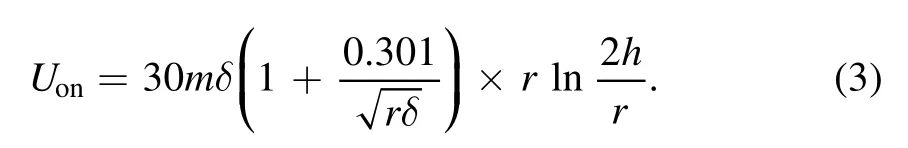
According to equation (3), it can be obtained that after the conductor is covered with dielectric film, the equivalent radius of the conductor can be enlarged, making the corona inception voltage increase.
In order to compare the influence of heterogeneous charges accumulated on the surface of the dielectric film on corona discharge,equation(1)should be rewritten as follows,since the charge amount on the surface of the medium is considered in this situation:
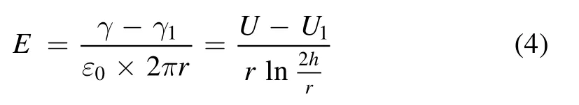
where γ1is the charge linear density on the surface of dielectric film, kC cm−1; andU1is the additional potential caused by the surface charge of the dielectric film,kV.It can be seen from equation (4) that heterogeneous charges accumulated on the of the medium have a certain weakening effect on the surface electric field of the covered conductor.Thus,the accumulated heterogeneous charges can reduce the corona discharge intensity.Moreover, the more charges accumulated, the more obvious the discharge suppression effect.

Figure 3.Relationship between electric field and voltage at different measuring points.(a) Bare conductor with diameter of 2 mm,(b)conductor covered with XLPE film with inner diameter of 2 mm and film thickness of 0.5 mm,and(c)bare conductor with diameter of 3 mm.

Figure 4.Comparison of the cross-section distribution of electric field under different voltages.(a) Bare conductor with diameter of 2 mm,(b)conductor covered with XLPE film with inner diameter of 2 mm and film thickness of 0.5 mm,and(c)bare conductor with diameter of 3 mm.
3.Results and discussion
3.1.Effect of dielectric film on corona discharge characteristics
3.1.1.Effect of dielectric film on the composite field strength.
In order to study the suppression effect of dielectric on DC corona discharge, the ground-level composite field strengths of the bare conductor(radius of 1 mm)and conductor covered with XLPE film (conductor diameter of 1 mm and film thickness of 0.5 mm) are compared.Figure 3 shows the ground-level composite field strength versus voltage curves of the two conductors at different measuring points.In the figure,the vertical dotted line represents the threshold voltage of the conductor, and the inclined dotted line represents the nominal field strength (NFS).Compared with the conductor covered with XLPE film, the discharge threshold voltage of the bare conductor is lower, which is due to the larger outer diameter of the conductor covered with XLPE film.Before discharge, the ground-level electric field strengths of the two kinds of conductors have little difference.After discharge,with the increase in voltage,the ground-level composite field strength under the bare conductor is much higher than the nominal field strength and the curve is curved upward,whereas the ground-level composite field strength of the conductor covered with XLPE film changes slowly and is lower than the nominal field strength.This indicates that there is heteropolar charge accumulated on the surface of the dielectric after corona discharge, which can significantly suppress corona discharge and greatly reduce the composite field strength under the transmission lines.However,with the increase in voltage, the ground-level composite field strength of the conductor covered with XLPE film still shows a slow increasing trend, which indicates that the increment of ground-level composite field strength cannot be completely suppressed by the conductor covered with dielectric film.In order to eliminate the influence of the outer diameter discrepancy between the bare conductor and conductor covered with XLPE film, figure 3(c) shows the variation of ground-level field strength with voltage for the bare conductor with a radius of 1.5 mm.At this time, the bare conductor starts to discharge at about 70 kV, which is consistent with that of the conductor covered with XLPE film, but the ground-level composite field strength of the bare conductor is still significantly higher than that of the conductor covered with XLPE film.
In order to compare the ground-level composite field strength of the bare conductor and conductor covered with XLPE film,the cross-section distributions of field strength of the three conductors under different voltages are shown in figure 4.Under the same voltage, the ground-level field composite field strength of the bare conductor is much higher than that of the conductor covered with XLPE film.For every 10 kV increment, the field-strength increment of the bare conductor is about five times that of the conductor covered with XLPE film, and the ground-level composite field strength of the bare conductor is more than twice that of the conductor covered with XLPE film at 100 kV.In addition,compared with the bare conductor with a radius of 1 mm,the ground-level composite field strength of the bare conductor with a radius of 1.5 mm decreases, which indicates that corona discharge can be suppressed by increasing the radius of the bare conductor, but it is not as effective as that of the conductor covered with dielectric film.
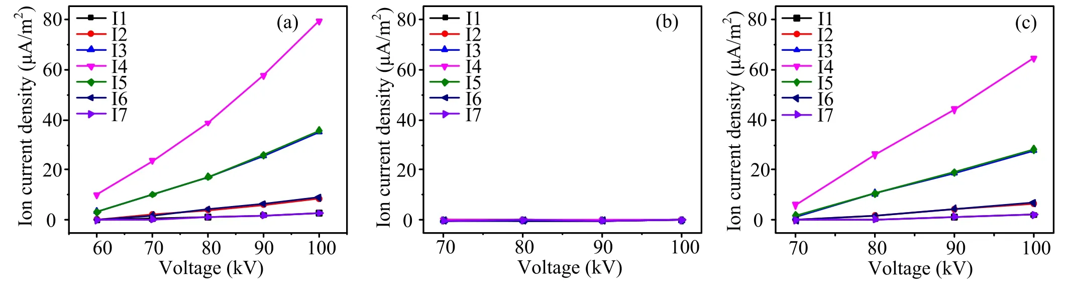
Figure 5.Relationship between ion current density and voltage at different measuring points.(a) Bare conductor with diameter of 2 mm,(b)conductor covered with XLPE film with inner diameter of 2 mm and film thickness of 0.5 mm,and(c)bare conductor with diameter of 3 mm.

Figure 6.Comparison of the cross-section distribution of ion current density under different voltages.(a) Bare conductor with diameter of 2 mm, (b) conductor covered with XLPE film with inner diameter of 2 mm and film thickness of 0.5 mm, and (c) bare conductor with diameter of 3 mm.
3.1.2.Effect of dielectric film on ion current density.Figure 5 shows the variation curves of ground-level ion current density with applied voltage at different measuring points of the three kinds of conductors.There is an enlarged view of the groundlevel ion current density of the conductor covered with XLPE film in the upper right corner of figure 5(b).After discharge,the ground-level ion current density of the bare conductor is at the μA m−2level,whereas that of the conductor covered with XLPE film is at the nA m−2level, which can be ignored compared with the bare conductor.In addition, the variation in ion current density of the conductor covered with XLPE film is not regular, which is because the ground-level ion current density is very small at this time, and the sampling resistance cannot accurately obtain the ion current.At the same time, it is also shown that the conductor covered with XLPE film can greatly reduce the ground-level ion current,so as to achieve the purpose of suppressing corona discharge.
Figure 6 shows the cross-section distribution of ion current density for the three conductors at different measuring points.With the increase in voltage, the ground-level ion current density of the bare conductor increases uniformly and presents symmetrical distribution, whereas that of the conductor covered with XLPE film basically does not increase and has no regularity.
3.2.Effect of film parameters on corona discharge characteristics
3.2.1.Effect of film thickness on corona discharge characteristics
3.2.1.1.Effect on composite field strength.The corona discharge can be suppressed by the presence of the dielectric film.Considering the economy, the film thickness should not be too thick.Therefore, it is necessary to study the effect of film thickness on corona discharge.Figure 7 shows the variation curve of ground-level composite field strength with applied voltage for XLPE conductors with inner diameter of 2 mm and film thicknesses of 0.5 mm,0.75 mm and 1 mm.Although increasing the film thickness can improve the threshold voltage of the conductor, the increment of film thickness does not make the ground-level composite field strength decrease gradually.After discharge,the relationship between the ground-level composite field strength and the film thickness is opposite, which is mainly caused by two reasons.(I) After discharge, the composite field strength of the conductor covered with dielectric film is lower than the nominal field strength.At the voltage of 70 kV,the conductor with film thickness of 0.5 mm has been discharged, whereas the conductors with film thicknesses of 0.75 mm and 1 mm have not been discharged, and their ground-level field strength is still the nominal field strength.Similarly, at the voltage of 80 kV, the conductors with film thicknesses of 0.5 mm and 0.75 mm have been discharged,whereas the conductor with film thickness of 1 mm has not been discharged.(II) The ground-level composite electric field strength is not completely suppressed by the conductor covered with dielectric film.The surface charge accumulation is saturated and the charge accumulation is related to the surface field strength of the conductor [20].
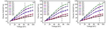
Figure 7.Comparison of electric field and voltage variation for conductors covered with XLPE film.(a) Inner diameter of 2 mm and film thickness of 0.5 mm,(b)inner diameter of 2 mm and film thickness of 0.75 mm,and(c)inner diameter of 2 mm and film thickness of 1 mm.
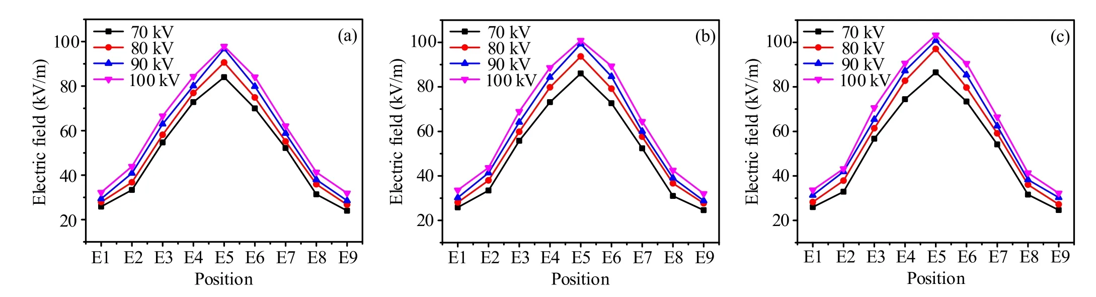
Figure 8.Comparison of the cross-section distribution of electric field under the conductor covered with XLPE films.(a) Inner diameter of 2 mm and film thickness of 0.5 mm, (b) inner diameter of 2 mm and film thickness of 0.75 mm, and (c) inner diameter of 2 mm and film thickness of 1 mm.
Figure 8 shows the cross-section distribution of the ground-level composite field strength of the three conductors under different voltages.It can be clearly seen that, with the increase in film thickness, the ground-level composite field strength gradually increases.In addition, with the increase in applied voltage, the increment of field strength at each measuring point gradually slows down, which indicates that the conductor covered with dielectric film can better suppress the enhancement of corona discharge under higher voltage.
3.2.1.2.Effect on ion current density.Figure 9 shows the variation curve of ground-level ion current density with applied voltage for the three kinds of conductors.With the increase in voltage, the ground-level ion current densities of the three kinds of conductors are all very small and irregular,and negative values even appear in some positions, which indicates that it is impossible to contrast the difference in the corona discharge suppression effect of film thickness through the ion current density.
Figure 10 shows the cross-section distribution of the ground-level ion current density for the three conductors under different voltages.With the increase in applied voltage,the cross-section distributions of ground-level ion current density of the three kinds of conductors are also irregular,and abnormal values appear at both ends.There is almost no ion current in the ground level of the three kinds of conductors,which indicates that corona discharge can be well suppressed as long as the film is covered.
3.2.2.Effect of film material on corona discharge characteristics
3.2.2.1.Effect on composite field strength.Different insulating materials have different surface microstructure and may have different charge accumulation and dissipation characteristics.Therefore,it is necessary to study the effect of film materials on corona discharge characteristics.Figure 11 shows the ground-level composite field strength curves of the conductors covered with XLPE film and PVC film,where the inner diameter is 1 mm and film thickness is 1 mm.Since the geometry of the two conductors is the same,they both start to discharge at about 80 kV.After discharge,compared with the conductor covered with PVC film, the field strength curve of the conductor covered with XLPE film bends down more,which indicates that XLPE insulation material has better ability to accumulate charges and suppress corona discharge than PVC insulation material.
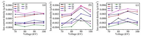
Figure 9.Comparison of ion current density and voltage variation for conductors covered with XLPE film.(a) Inner diameter of 2 mm and film thickness of 0.5 mm,(b)inner diameter of 2 mm and film thickness of 0.75 mm,and(c)inner diameter of 2 mm and film thickness of 1 mm.

Figure 10.Comparison of the cross-section distribution of ion current density under conductors covered with XLPE films.(a)Inner diameter of 2 mm and film thickness of 0.5 mm,(b)inner diameter of 2 mm and film thickness of 0.75 mm,and(c)inner diameter of 2 mm and film thickness of 1 mm.

Figure 11.Comparison of electric field with voltage variation under different film materials:(a)conductor covered with XLPE film with inner diameter of 2 mm and film thickness of 1 mm,and(b)conductor covered with PVC film with inner diameter of 2 mm and film thickness of 1 mm.
Figure 12 shows the cross-section distribution of electric field under the two kinds of conductors with different voltages.The corresponding black curve at 70 kV represents the cross-section distribution of electric field without discharge, and the ground-level composite field strengths of the two kinds of conductors are basically the same.However,with the increase in voltage,the increment of the ground-level field strength of the conductor covered with XLPE film is lower than that of the conductor covered with PVC film,which also indicates that XLPE insulation material has better ability to suppress the corona discharge.

Figure 12.Comparison of the cross-section distribution of electric field under different film materials:(a)conductor covered with XLPE film with inner diameter of 2 mm and film thickness of 1 mm, and (b) conductor covered with PVC film with inner diameter of 2 mm and film thickness of 1 mm.
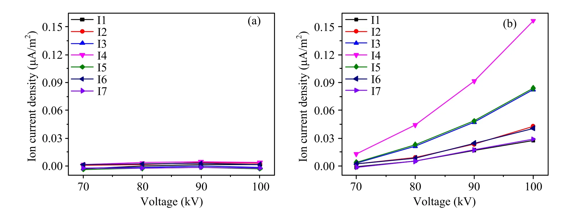
Figure 13.Comparison of ion current density with voltage variation under different film materials: (a) conductor covered with XLPE film with inner diameter of 2 mm and film thickness of 1 mm, and (b) conductor covered with PVC film with inner diameter of 2 mm and film thickness of 1 mm.
3.2.2.2.Effect on ion current density.Figure 13 shows the ground-level ion current density curves of two kinds of conductors.With the increase in voltage, the ground-level ion current density of the conductor covered with XLPE film basically does not increase and a negative value even appears in some positions,which indicates that corona discharge has hardly occurred.The ground-level ion current density of the conductor covered with PVC film increases with the increase in voltage,which indicates that corona discharge has occurred to a certain degree.Therefore, it can be seen from the ion current density that XLPE material has better ability to suppress corona discharge than PVC material.However, compared with the bare conductor,the conductor covered with PVC film still has a good ability to suppress corona discharge.
Figure 14 shows the cross-section distribution of ion current density under the two kinds of conductors with different voltages.The ground-level ion current density of the conductor covered with XLPE film still has negative values and the positions I3 and I5 are abnormal.This reveals that the ion current density of the conductor covered with XLPE film is very small, and the measurement results are easily affected by external factors.However, the groundlevel ion current density of the conductor covered with PVC film increases with the increase in applied voltage and has good symmetry,which indicates that PVC material does not have excellent ability to suppress corona discharge at higher voltage.
3.3.Effect of film materials on surface charge accumulation and dissipation characteristics
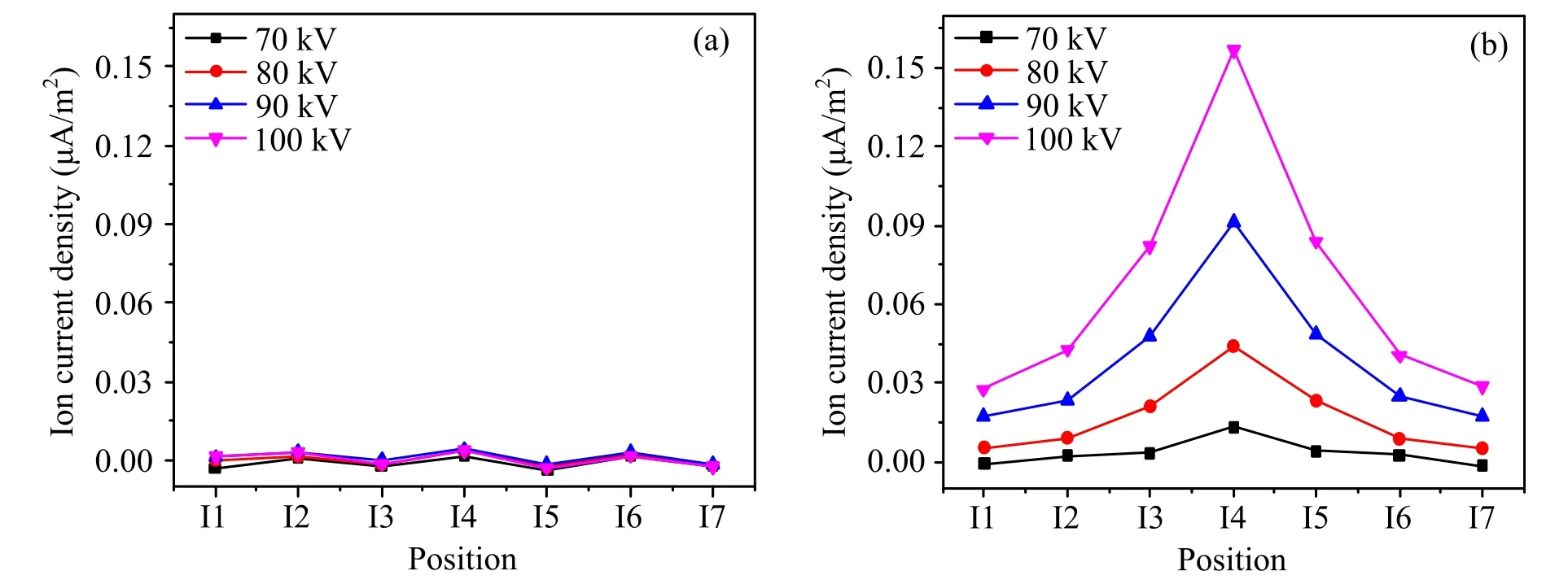
Figure 14.Comparison of the cross-section distribution of ion current density under different film materials: (a) conductor covered with XLPE film with inner diameter of 2 mm and film thickness of 1 mm,and(b)conductor covered with PVC film with inner diameter of 2 mm and film thickness of 1 mm.

Figure 15.Relationship between electric field and voltage in different film materials after the voltage disappears.
3.3.1.Effect of film materials on surface charge accumulation characteristics.In this paper, a DC field strength meter is used to measure the ground-level field strength at position E5 after voltage disappearing, so as to obtain the polarity of the accumulated charge on the film surface, and then to judge the accumulation mode of the surface charge [21].Figure 15 shows the ground-level field strength of position E5 at zero time after voltage disappearing for the conductors covered with XLPE film and PVC film.Under the action of a normal electric field,the ionized charge in air migrates to the surface of the dielectric and forms a surface charge.The negative ground-level field strength indicates that the surface of the conductor accumulates negative charge, which shows that the surface charge accumulation mode of the conductor covered with dielectric film is mainly gas side conduction[23,24].In addition,with the increase in applied voltage,the surface charge accumulation increases gradually, which is because the higher the voltage is,the greater the surface field strength is.In order to suppress corona discharge, more charges are needed to accumulate on the surface of the conductor to weaken the original field strength.With the increase in applied voltage, the increment of the groundlevel electric field of the conductor covered with PVC film at zero moment decreases gradually, and it is obviously lower than that of the conductor covered with XLPE film.This reveals that the ability to accumulate charge of the conductor covered with PVC film becomes weaker at higher voltage,which may be caused by the microstructure of the material.This also explains why the ground-level composite field strength of the conductor covered with PVC film in section 3.2.2 is higher than that of the conductor covered with XLPE film,and a certain amount of ion current density appears at ground level.Therefore, from the surface charge accumulation characteristic, it is also confirmed that XLPE material has better ability to suppress corona discharge.
3.3.2.Effect of film materials on surface charge dissipation characteristics.Figure 16 shows the attenuation curves of ground-level field strength with time for both conductors.After the voltage disappears, the ground-level field strength shows an exponential decay trend from fast to slow.The ground-level field strength of the conductor covered with PVC film has basically decreased to 0 kV m−1after 30 min,whereas that of the conductor covered with XLPE film attenuates slowly and eventually stabilizes at a nonzero value, which indicates that the XLPE material has slower charge dissipation rate.After the voltage disappears, the discharge rod is used to release the surface charge of the conductor.It is found that the conductor covered with XLPE film has an obvious ‘crackle’ sound, whereas the conductor covered with PVC film has no sound.For the line-plate device, the charge is uniformly accumulated on the surface of the conductor, so the surface dissipation mode is very weak.There are three methods of surface charge dissipation: volume dissipation, surface dissipation, and air neutralization dissipation [25, 26].Due to the large distance between the wire plates and the uniform electric field on the surface of the medium, it can be considered that the charge on the surface of the medium is uniformly distributed.In addition, due to the small contact area of the experimental device on the edge of the medium during the test, the influence of surface charge dissipation along the surface can be ignored.For air neutralization dissipation, the amount of charge in the air after discharge is determined by the external environment; in other words, for XLPE and PVC materials,the rate of air neutralization and dissipation is roughly equal.It can be clearly seen from figure 16 that the dissipation rate of the surface charge of the PVC material is significantly higher than that of the XLPE material, so the dissipation method of the surface charge of the PVC material can include volume dissipation in addition to air neutralization dissipation.
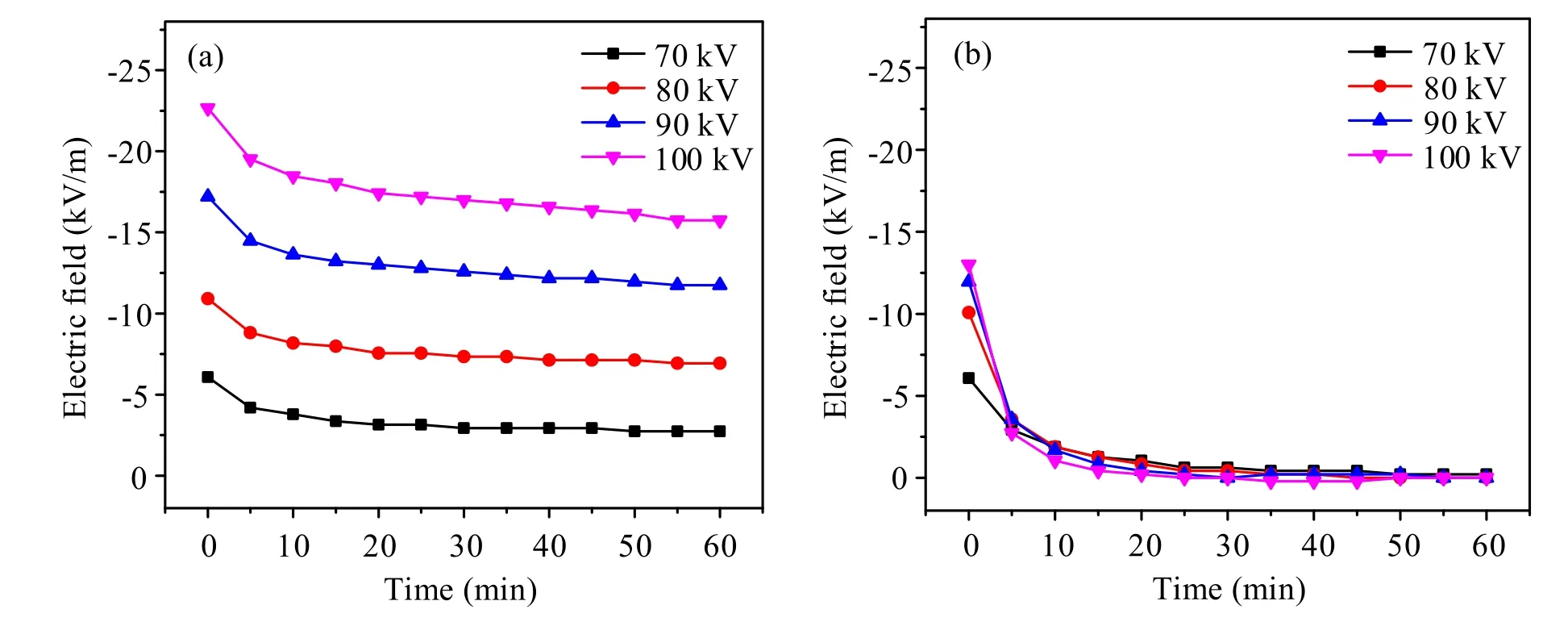
Figure 16.Relationship between electric field and time for different film materials after voltage disappears:(a)conductor covered with XLPE film and (b) conductor covered with PVC film.
4.Conclusions
In this paper, the suppression effect of a dielectric-film-covered conductor on corona discharge is confirmed.Corona discharge suppression under different film thicknesses and film materials is studied.Furthermore, the effect of film material on the characteristics of charge accumulation and dissipation is explored.The main conclusions are as follows:
(1) The conductor covered with dielectric film has excellent ability to inhibit corona discharge.By comparing the discharge characteristics of the bare conductor with 2 mm diameter and the XLPE-covered conductor with 2 mm inner diameter and 0.5 mm film thickness,experimental results can be obtained.The ground-level field strength of the conductor covered with dielectric film is much lower than its nominal field strength.The ground-level ion current density of the conductor covered with dielectric film is of the order of nA m−2, which means that in the covered conductor condition there is almost no ion current compared with the bare conductor.
(2) Increasing the film thickness can increase the threshold voltage.However, the thickness of the dielectric film does not have an obvious effect on the ground-level composite field strength after discharge.The XLPE material has stronger ability to suppress corona discharge than the PVC material.Compared to the PVC material, the XLPE material has stronger charge accumulation ability and slower charge dissipation rate.
(3) The inhibition of corona discharge in HVDC transmission lines is an important issue due to the negative effect the corona discharge can introduce.In this work,the suppression effect on the corona discharge of a dielectric-film-covered conductor has been proven.However, considering the cost of covering the entire line,we suggest this method can be considered in cases of wire terminals such as converter stations.Besides,in these occasions the corona discharge can be stronger and has a huge effect on the electrical equipment.
(4) Compared to the HDVC conductors,the conductor used in this work to investigate the effect of a barrier film on the inhibition of corona discharge is a reduced-scale model.Further studies still need to be performed to identify a feasible film thickness for real HDVC conductors.
Acknowledgments
This work is supported by State Grid Shandong Electric Power Company (52062618001M).
猜你喜欢
杂志排行
Plasma Science and Technology的其它文章
- Effect of edge turbulent transport on scrapeoff layer width on HL-2A tokamak
- An investigation on improving the homogeneity of plasma generated by linear microwave plasma source with a length of 1550 mm
- Spatio-temporal evolution characteristics and pattern formation of a gas–liquid interfacial AC current argon discharge plasma with a deionized water electrode
- Turbulent boundary layer control with a spanwise array of DBD plasma actuators
- Plasma activation towards oxidized nanocarbons for efficient electrochemical synthesis of hydrogen peroxide
- Spatio-temporal evaluation of Zr plasma parameters in a single-beam-splitting double-pulse laser-induced plasma