Numerical simulations of vortex-induced vibrations of a flexible riser with different aspect ratiosin uniform and shear currents *
2017-03-14YuDuanmu端木玉LuZou邹璐DechengWan万德成
Yu Duanmu (端木玉), Lu Zou (邹璐), De-cheng Wan (万德成)
1. State Key Laboratory of Ocean Engineering, School of Naval Architecture, Ocean and Civil Engineering,Shanghai Jiao Tong University, Collaborative Innovation Center for Advanced Ship and Deep-Sea Exploration,Shanghai 200240, China
2. Guangzhou Maritime University, Guangzhou 510725, China, E-mail: duanmuyu1023@163.com
Introduction
Vortex-induced vibration (VIV) is a critical concern of the offshore industry, including pipelines,spar platforms and risers, among which the greatest concern is over the field of deep-water oil extraction.Recently, offshore oil platforms have been installed in water depths of over 2 000 m. As a result, it is urgent to develop a reliable numerical method for predicting the VIV responses of risers with very high aspect ratios. Faltinsen[1]gave an overview of hydrodynamic problems related to the broad variety of ships and sea structures involved in oil and gas exploration and production.
Over the past few decades, VIV responses of long flexible risers have been extensively studied.Model testing has given valuable insights into the phenomenon of VIVs[2-5]. In these model tests, it was observed that the responses included significant contributions from several modes except at the lowest reduced velocities, a temporary mode transition also occurred occasionally. Apart from the experimental studies, numerical investigations have also attracted researchers. Empirical modals and computational fluid dynamics (CFD) models are the two main numerical methods used to predict the vibrations of risers[6-13].Willden and Graham[6]investigated the CF VIVs of a flexible riser with an aspect ratio of the order of 1 000.It has been observed that the vibration mode with frequency closest to the local natural vortex shedding frequency is most likely to be excited. Shen et al.[14]investigated the near wake structure, the wake flow characteristics and the drag coefficients behind a modified square stay-cable. The detailed near wake structures, the velocity fields and the force coefficients for the cable were captured. Loannis et al.[15]investigated a vertical cylinder due to the impact of a steep wave that is moving with a steady velocity.Zhang et al.[16]investigated the flow past a finite cylinder with a height-to-diameter ratio of 1.5 and an infinite circular cylinder at a R e = 3900 using the large eddy simulation.
For risers having such high aspect ratios and complex flow fields around them, a complete threedimensional simulation is not feasible. The strip theory is an efficient strategy for solving VIV problems of flexible cylinders with extremely high aspect ratios. Based on strip theory, the solver viv-FOAMSJTU were developed by using the open source code package, OpenFOAM. The entire fluid-structure solution procedure was carried out in the time domain via a loose coupling strategy. The mesh movement based on the interpolation using the radial basis function(RBF) was applied.The solver had good versatility,allowing simulations of VIVs in both CF and IL directions with various aspect ratios, mass ratios, top tensions and current profiles. Chen et al.[17]used OpenFOAM to investigate roll motion of a twodimensional rectangular barge in viscous flow.
To validate the solver, we had carried out numerical simulations of the VIVs benchmark case[18,19-21].The numerical results were found to be in good agreement with the benchmark data given in Huera Huarte[4]. Base on the study of the flow field, the intrinsic relationship between the flow field and the vibration response of the riser was analyzed. In regard to VIVs of a long flexible riser, parametric analysis on current velocity, top tension and mass ratio has been carried out by a lot of studies. However, only a few studies focus on the effect of aspect ratio.The main object of this paper is to investigate the effects of aspect ratio on the VIV based on the solver viv-FOAM-SJTU. The results for uniform and shear currents acting on single, flexible cylinders, with aspect ratios varying from 500 to 1 000, are shown.
1. Method
1.1 Flow modal
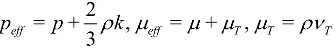
The flow field is modelled by solving the unsteady, incompressible Reynolds-averaged Navier-Stokes equations


Fig.1 Fluid-structure interaction


The Reynolds-averaged approach to turbulence modelling requires that the Reynolds stresses be appropriately modelled. A common method employs the Boussinesq hypothesis to relate the Reynolds stresses to the mean velocity gradients

where the turbulence kinetic energy, k is defined as

andTν is the kinetic eddy viscosity assumed as an isotropic scalar quantity. The SST -kω model is adopted for turbulence closure. Thus


Fig.2 (Color online) Illustration of multi-strip model (/ =L D 500)

Fig.3 (Color online) Domain and mesh of a strip

Fig.4 The mean IL displacement (L/ D =500)

Fig.5 The rms CF displacement (L/ D =500)
where
1.2 Structural dynamic model
A finite-element structural model based on the Euler-Bernoulli beam theory is employed to calculate the dynamic response of the cylinder. Supposing that EIand m*remain constant along the span, we have
The axial force of the pipe ()T z varies spatially but not temporally, because of the effects of the weights.To solve it in finite-element methods (FEMs), Eq.(7)and Eq.(8) can be discretized as

where {x} and {y} are the nodal displacement vectors, with dots denoting differentiation with respect to time, [M], [C] and [K] are the mass, damping and stiffness matrix, respectively. {Fx} and {Fy}are the hydrodynamic force vectors. The governing equations are solved using the Newmark-beta method.
1.3 Fluid-structure interaction
The strip theory CFD model is used to simulate the fluid dynamics. The fluid flow computed locally in multiple two-dimensional computational planes is placed along the cylinder span. The PIMPLE (merged PISO-SIMPLE) algorithm in OpenFOAM is adopted to compute the flow field, which is appropriate for solving the transient incompressible problem. The reliability of this locally two-dimensional method has already been confirmed[6].
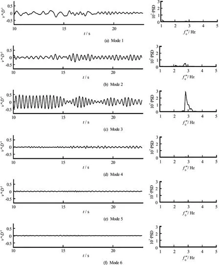
Fig.6 The CF modal amplitude and PSD of modal amplitudes in uniform flow (L/ D =500)
The fluid force on the individual axial strips is mapped to the nodes of the structural model at the start of each time step. Subsequently, this is used to compute pipe’s motion based on the Euler-Bernoulli beam theory, and the motion provides information for moving the boundaries in the fluid domain. Then, a new flow field is computed. In this way, a time step is advanced. This procedure is shown in Fig.1. Based on the above theory the solver viv-FOAM-SJTU is developed. The entire flow-structure solution procedure is carried out in the time domain by using a loose coupling strategy.
1.4 Radial basis function interpolation
Many of the analyses of vortex induced vibration of flexible risers neglect the influence of the in-line motion. However, from the fatigue point of view, the curvatures of the in-line and cross-flow vibrations are quite similar. Due to the increase of the aspect ratio of the riser, the mean in-line displacement of the riser is also significantly increased, which brings a challenge to the moving grid technology. The viv-FOAM-SJTU solver applies the RBF dynamic grid technique to the solution of dynamic mesh of OpenFOAM, so that the solver could transcend the limitations of Laplace mesh deformation, to simulate the VIV in both IL and CF directions of flexible riser with aspect ratio of 1 000 magnitude under high Reynolds number.
Fig.7 (Color online) Spatio-temporal plot of the CF response
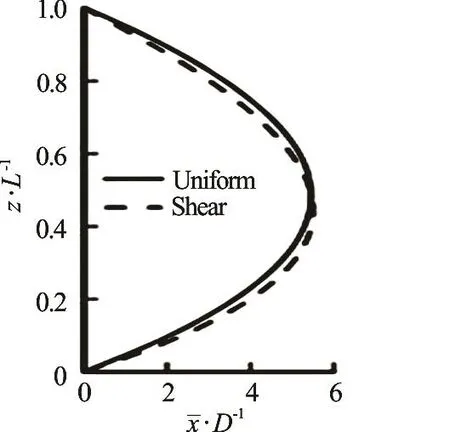
Fig.8 The mean IL displacement (L/ D =500)
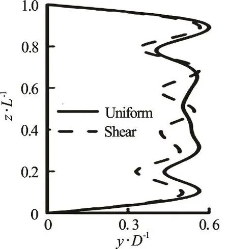
Fig.9 The rms CF displacement (L/ D =500)

Fig.10 The CF instantaneous shapes
It is always expected to find the mesh solution method which is not only efficient and capable to endure large mesh deformation, but also maintain the quality of the grid after deformation (especially the grid in the boundary layer). The perfect solution of the above three difficulties is realized by the RBF grid technique. If the inner and outer diameters are set appropriately, the grid inside the boundary layer could keep relatively static, and the mesh quality and the deformation ability of the mesh will also be secured.
The RBF dynamic grid technique based on the dynamic mesh module of Open FOAM was developed.The RBF interpolation, which was first proposed by Rendall and Allen[22], can be used to derivethe displacement of the internal fluid nodes when the displacement of the structural nodes on the interface is given.
The RBF is a set of basis functions with Euclidean distances defined as follows.
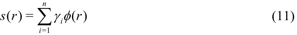
where r is the Euclidean distance, and ()rφ is the general form of the RBF function which has various forms. There are four commonly used functions: C2,TPS, Gauss and IMQB, the definitions of these functions are given in Table 1. The parameteriγ is the interpolation weight coefficient for the interpolation point i, and n is the number of the object surface nodes of the dynamic mesh.
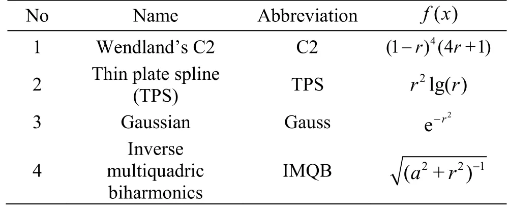
Table 1 Definition of radial basis functions
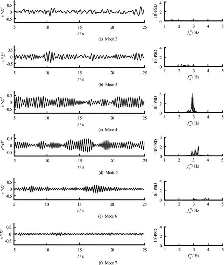
Fig.11 The CF modal amplitudes and PSD of modal amplitudes in uniform flow (L/ D =750)
1.5 Post processing
Following Chaplin et al.[3], the IL and CF deflecttions of the riser from the initial vertical straight-line condition are denoted by x( z, t) and y( z, t), respectively, z is the elevation.
The deflected shape of the riser can be represented in spectral terms, which means that each pipe’s total displacement can be decomposed into modal contributions. The displacements in IL and CF directions can then be expressed in terms of time-dependent modal weights u=(u1, u2,… ,uM)and v=

where φ =(φ1, φ2,… ,φM)is the matrix of mode shapes and Mis the number of unconstrained structural degrees of freedom. m is the mode number.
The matrix of of Eq.(12) and Eq.(13) are

Fig.12 The CF modal amplitudes and PSD of modal amplitudes in shear flow (L/ D =750)

Spatial frequency analysis can also be performed over the curvatures. Let us take the second derivative of Eq.(12) and Eq.(13) and assume that [φm( z)]′=-k2m2φm(z)is satisfied where k is constant, i.e.,the mode shapes are exactly sinusoids or something similar. Therefore

where the prime sign denotes differentiation with respect to z, cxand cyare the in-line and crossflow curvature. cx= x′ /(1 + x ′ )3/2≈ x ′ is considered suitable for this study, as well as for cy, because x′is always far below 1. Thus, the modal weights for the curvature - k2m2umand - k2m2vmcan be of high absol
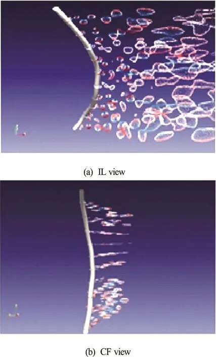
Fig.13 (Color online) Vortex-shedding along the riser from IL and CF view

Fig.14 The mean IL displacement (L/ D =1000)
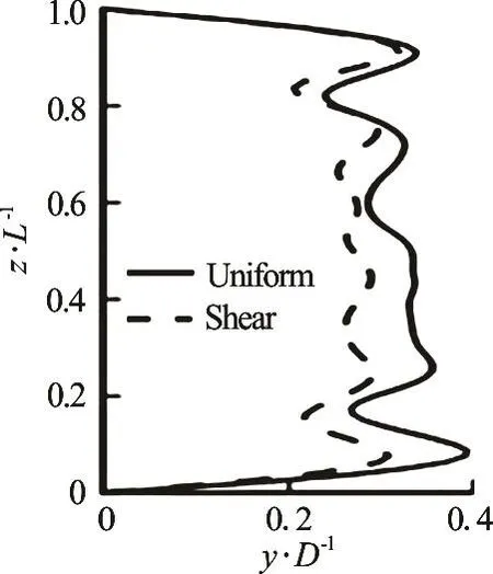
Fig.15 The rms of the CF displacement (L/ D =1000)

where only the desirable mode shapes are included in.φ
2. Numerical results and discussion
2.1 Description of the problem
In the present study, numerical simulations are performed for a riser subjected to two types of current profiles: one is a uniform profile and the other is a linearly decaying sheared profile. The velocity of uniform current is 0.4 m/s. The sheared current profiles introduced in the tests are characterized by a shear parameter S, which is defined as

where Umaxis the maximum current velocity at the lower end of the riser, Umindenotes the minimum current velocity at the upper end of the riser; and Umeansignifies the mean velocity. A sheared profile with S =0.5 is considered. The mean velocity of these sheared tests is 0.4 m/s, the sheared current speed has a linear profile with 0.3 m/s at top and 0.5 m/s at bottom. Thus, the areas for both the uniform profile and the sheared profile are the same.almost the same as those ofChaplinetal.[3,4], with key
The model riser andexperimental settingare parameters setting out as in Table 2. With the same parameters, the length-to-diameter ratio (aspect ratio)shows a significant influence on VIV of a long flexible riser. Besides, the increase of the aspect ratio of the riser affects not only the vibration mode of the riser, but also the IL equilibrium position.
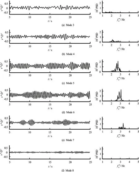
Fig.16 The CF modal amplitudes of the riser and PSD of modal amplitudes in uniform flow (L/ D =1000)
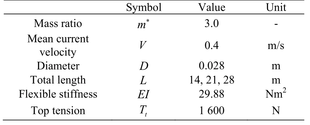
Table 2 Key parameters for the benchmark experiment
This paper aims to study the VIV responses of a long flexible riser by varying the length-to-diameter ratio. The diameter is fixed while the length of the riser varies so as to obtain different aspect ratios. Three different aspect ratios are studied: / =L D 500, 750 and 1 000.
2.2 Numerical model and boundary conditions
The distribution of strips is placed equidistantly along the length of the riser. The space between strips and structure elements are the same for different aspect ratio cases, which results in 20, 30, and 40 strips for / =L D 500, 750 and 1 000, respectively.The grid number of each strip is 36 550. For the cases with different aspect ratios, the total grid number of different cases is 731 000, 1 096 500 and 1 462 000,respectively. The corresponding numbers of structure elements are 80, 120 and 160. Figure 2 shows the dis-tribution of 20 strips placed at an equal distance along the riser for L / D = 500.The riser is discretized into 80 equal structural elements, each of which adopts a distributed load.

Fig.17 The mean IL displacement and curvature of riser subjected to uniform and shear flow

Fig.18 CF modal rms vibration amplitudes, /D, as a function of modal natural frequencies /f, with s different aspect ratio in uniform and shear flow
The computational mesh of each strip is shown in Fig.3. The boundary conditions are given as follows:
The boundary conditions of the inlet velocity are set to be the same as those of the free stream velocity

The outflow boundary condition is defined by

The symmetry boundary condition is applied to other sides of the domain to avoid the effect of the boundaries on the flow field

The no-slip boundary condition is employed at the surface of the cylinder. The velocity of the cylinder boundary must agree with the pipe motion calculated using the three-dimensional FEM structural analysis

2.3 Modal analysis of riser with L / D =500
The riser is 28 mm in diameter and 14 m in length, with an aspect ratio of about L / D = 500. The other parameters, such as top tension, mass ratio, and modulus of elasticity, are listed in Table 2. Figure 4 depicts the mean IL displacement, plotted against the relative elevation z / L. The solid line represents the numerical results in uniform flow while the dotted line refers to the results in shear flow. The location of the maximum displacement is in the middle length for the riser subjected to uniform current. However, the position in sheared current is a bit lower, with a distance of 0.45L from the bottom of the riser. The maximum IL mean displacement for uniform and sheared cases is almost the same, which is about 3 times the diameter, as shown in the Table 3.

Table 3 the maximum IL mean displacement and its location (L/ D =500)
Figure 5 shows the rms of the CF displacement.The rms values of the both curves exhibit the 3rdmode shape in the two types of current profiles. The Solid line, which represents the CF vibration in uniform flow, presents a better symmetry property.
To manifest the modal feature, especially the multi-mode feature, displacements have been decomposed into its modal contributions. The vibrations in uniform flow and in shear flow display a characteristic resemblance.
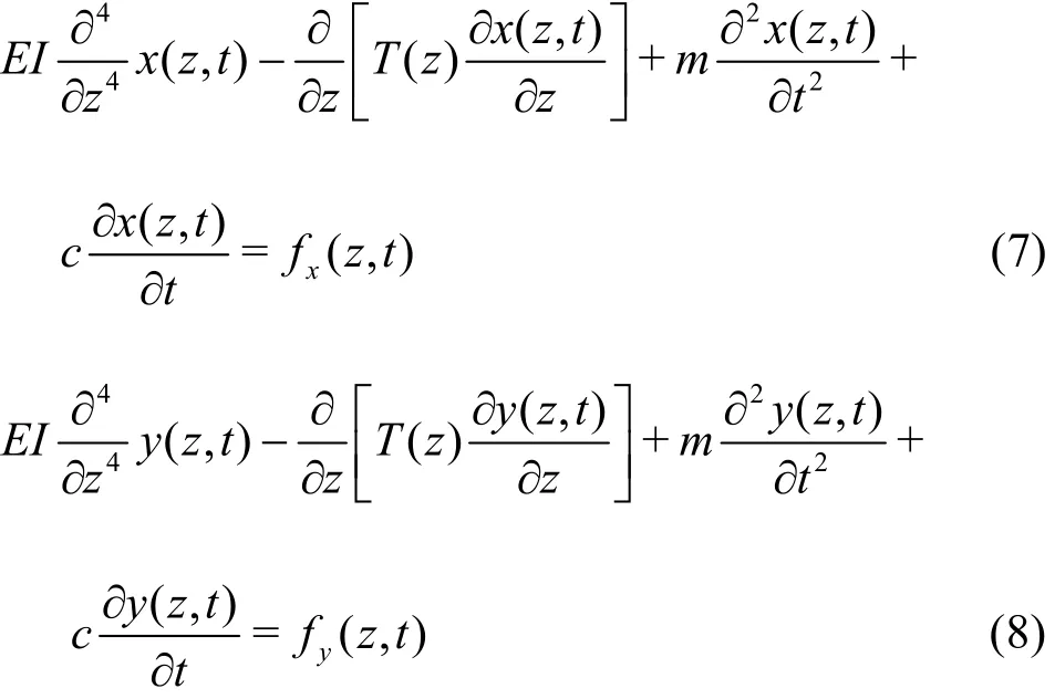
Because the dominant mode in uniform flow is similar to that in shear flow, the vibration in uniform flow is taken as an example for analysis. However,there are subtle differences in the modal amplitude over time. Figure 6 shows the CF modal amplitudes of the riser and the power spectra density (PSD) of modal amplitudes in uniform and shear flow, respectively. The 3rdmode is the dominant mode, and the PSD of the other modes is almost zero. It suggests that the dominant mode shape is controlled only by the 3rdmode. There is no transition of mode, which shows a standing wave response of CF vibration. The spatiotemporal plot of the CF responses exhibits the above information in an intuitive way, as shown in Fig.7.When the aspect ratio is 500, there is no remarkable difference of the CF responses in both uniform flow and shear flow.
2.4 Modal analysis of riser with L / D =750
By increasing the aspect ratio to L / D = 750,there will be changes of oscillating mode and IL equilibrium position, as well as a big difference of VIV responses between in uniform and in shear flows. The maximum IL mean displacement increases with the aspect ratio. As shown in the Fig.8 and Table 4, the maximum IL mean displacement increases to about 5.5 times the diameter. Nonetheless, the location of this maximum is unchangeable because the current profile along the riser length is not changed.
Figure 9 shows the rms value of the CF displacement. The responses in uniform flow are marked with a solid line and the results in shear flow are marked with a dotted line. Distinguishable differences can be observed: the RMS value in uniform flow appearsthe order mode shape while the RMS value in shearflow displays the order modeshape.Figure10 presents the CF instantaneous shapes in uniform flow and shear flow, which also shows the different dominant modes of CF vibration between in uniform flow and in shear flow.tion inCF direction isdominated bythemode
Asispresentedin previous subsection,thevibrawhen aspect ratio is 500. When the aspect ratio increases to 750, the CF vibrational mode of the riser also increases accordingly. The CF oscillation in uniform flow (Fig.11) shows multi-mode vibration of the 4thand 5thmode, of which the dominant mode is the 4thorder. Therefore, in shear flow (Fig.12), the riser also shows multi-mode vibration of the 4thand 5thmode, but the dominant mode is the 5thmode.Figure 13 shows the vortex shedding along the riser from the IL and CF view angles. With the increase of the aspect ratio, the vibration of riser changes from single mode to multi-mode pattern, and the multiple mode is obtained for the vibrations in both uniform and shear flows. The standing wave and travelling wave responses are captured for different aspect ratios.

X D Location max/Uniform 5.482 0.50L Shear 5.496 0.45L
2.5 Modal analysis of riser with L / D =1000
When the length of the riser increases to 28 m,and the corresponding aspect ratio reaches 1 000. The maximum value of the equilibrium position of the CF vibration will increase to more than 8 times the diameter, but the position corresponding to the maximum value still will not change. Specific information is shown in Fig.14 and Table 5.

Table 5 The maximum IL mean displacement and its location (L/ D =1000)
Figure 15 shows the rms value of the riser’s CF displacement, from which the dominant CF vibration mode of the riser is difficult to identify. However,when the aspect ratio is small like L / D = 500 and L/ D = 750, the vibration mode from the rms value of the CF displacement can be identified easily. It can be explained from the analysis of CF modal amplitudes and energy spectrum. The VIV responses for the case of L / D = 750 present a multi-mode vibration. Although there are two or more mode shapes presenting during the vibration, there is only one dominant mode.But the VIV responses for the case of L / D =1000 present another kind of multi-mode vibration. The increase of aspect ratio leads to multi-dominant mode of CF vibrations, there are two dominant modes during vibrationas shownin the Fig.16. The modal weights of the,andmodes are high,of whichthe modal weightsof the and modes are close,serving as the dominant modes. There are three main vibration modes and two dominant modes as the aspect ratio increases to 1 000. The interaction of multi-dominant mode leads to the failure of identifying CF vibration mode from the RMS value.The IL vibrations have the similar feature with the CF vibration, and the multi-dominant character of IL vibration is more obvious. The modal weights of the 10th, 11thand 12thare high, and both the modal weight of the 11thand 12thmodes are close, which are the dominant modes in uniform and shear flow. The riser’s vibration changes from one dominant mode to multi-mode with the increase of aspect ratio. The vibration mode is difficult to identify due to the high IL mode and multi-dominant mode.
2.6 Comparison of different aspect ratio
Figure 17 is the mean IL displacement and curvature of riser with different aspect ratios subjected to uniform and shear flow respectively. The increase of aspect ratio exerts a large effect on the IL equilibrium position of the riser, while with little effect on the curvature of riser. In uniform flow, the riser’s IL displacement is symmetrical and the curvature distributes uniformly. In shear flow, the riser’s IL displacement is asymmetrical and the curvature skews downward.
The aspect ratio has a large effect on the vibration mode of the riser. The vibration mode increases and changes from single mode to multi-mode with the increase of aspect ratio. The rms of the CF modal weight historiesin uniform and shear flow is shown in Fig.18, as a function of each mode’s natural frequency normalized upon the strouhal frequency of the stationary pipe at the same Reynolds number, fs
3. Conclusion
In this paper, an investigation of VIV of flexible riser with different aspect ratios in uniform and shear flow was carried out. The VIV responses of the vertical riser with aspect ratio of 500, 750 and 1 000 in the uniform flow and shear flow were investigated.The simulation was carried out by our in-house computational fluid dynamics (CFD) solver viv-FOAMSJTU, which applied the RBF dynamic grid technique into the solution of dynamic mesh. The RBF dynamic grid technique could keep the grid relatively static in the inner diameter range, so the mesh quality inside the boundary layer guaranteed when the IL displacement was large. The advantage of the RBF dynamic grid technique accomplished the numerical simulation of vortex-induced vibrations of a long flexible riser with high aspect ratio. The equilibrium position of the IL direction and the vibration mode of the riser would increase with the increase of the aspect ratio. When the aspect ratio was 500, the CF vibration was shown as a standing wave with a 3rdorder single mode. As the aspect ratio increased, the CF gradually turned into multi-mode vibrations. When the aspect ratio was 1 000, the vibration became more complex with two dominant modes and several vibration modes.The flow profile had an influence on the modal weight of each mode leading to different modal responses of the riser in uniform and shear flow during vibration.In general, the effect of flow profile would not change the dominant mode of vibration. Under certain conditions, the shear flow could excite modes that were slightly higher than those of the uniform flows.
Acknowledgement
This work was supported by the Chang Jiang Scholars Program (Grant No. T2014099), the Shanghai Excellent Academic Leaders Program(Grant No. 17XD1402300), the Program for Professor of Special Appointment (Eastern Scholar) at Shanghai Institutions of Higher Learning (Grant No. 2013022),the Innovative Special Project of Numerical Tank of Ministry of Industry and Information Technology of China (Grant No. 2016-23/09) and Lloyd’s Register Foundation for Ph. D. Candidate, to which the authors are most grateful.
[1] Faltinsen O. M. Hydrodynamics of marine and offshore structures [J]. Journal of Hydrodynamics, 2015, 26(6):835-847.
[2] Chaplin J., Bearman P., Cheng Y. et al. Blind predictions of laboratory measurements of vortex-induced vibrations of a tension riser [J]. Journal of Fluids and Structures,2005, 21(1): 25-40.
[3] Chaplin J., Bearman, P., Huarte F. H. et al. Laboratory measurements of vortex-induced vibrations of a vertical tension riser in a stepped current [J]. Journal of Fluids and Structures, 2005, 21(1): 3-24.
[4] Huera Huarte F. J. Multi-mode vortex-induced vibrations of a flexible circular cylinder [D]. Doctoral Thesis,London, UK: The University of London, 2006.
[5] Huera Huarte F. J., Bearman P. W., Chaplin J. R. On theforce distribution along the axis of a flexible circular cylinder undergoing multi-mode vortex-induced vibrations[J]. Journal of Fluids and Structures, 2006, 22(6):897-903.
[6] Willden R. H. J., Graham J. M. R. Multi-modal vortexinduced vibrations of a vertical riser pipe subject toa uniform current profile [J]. European Journal of Mechanics-B/Fluids, 2004, 23(1): 209-218.
[7] Srinil N. Multi-mode interactions in vortex-induced vibrations of flexible curved/straight structures with geometric nonlinearities [J]. Journal of Fluids and Structures,2010, 26(7): 1098-1122.
[8] Wang J. S., Zhan L. L., Jiang S. Q. et al. Numerical simulation of VIV for a marine riser in uniform and linearly sheared currents [C]. Proceedings of the Twenty-third(2013) International Offshore and Polar Engineering.Anchorage, Alaska, USA, 2013, 501-507.
[9] Wang J. F., Wan D. C. Numerical simulation of 3-D water collapse with an obstacle by FEM-level set method [J].Journal of Hydrodynamics, 2015, 27(1): 112-119.
[10] Fu B. W., Duanmu Y., Wan D. C. Vortex-induced vibrations of a flexible cylinder experiencing an oscillatory flow [C]. The twenty-seventh International Offshore and Polar Engineering Conference, San Francisco, California,USA, 2017.
[11] Duanmu Y., Wan D. C. Large eddy simulation of flow around the cylinders with different aspects [J]. Chinese Journal of Hydrodynamics, 2016, 31(3): 295-302(in Chinese).
[12] Zhao W. W., Wan D. C. Detached-eddy simulation of flow past tandem cylinders [J]. Applied Mathematics and Mechanics (Engilsh Edition), 2016, 37(12): 1272-1281.
[13] Zhao W. W., Wan D. C. Numerical study of 3D flow past a circular cylinder at subcritical Reynolds number using SST-DES and SST-URANS [J]. Chinese Journal of Hydrodynamics, 2016, 31(1): 1-8(in Chinese).
[14] Shen S. C., Wang M., Lu H. et al. The numerical and experimental investigations of the near wake behind a modified square stay-cable [J]. Journal of Hydrodynamics, 2016, 28(5): 897-904.
[15] Loannis K. C., Alexander A. K., Mark J. C. Threedimensional steep wave impact on a vertical cylinder [J].Journal of Hydrodynamics, 2016, 28(4): 523-533.
[16] Zhang H., Yang J. M., Xiao L. F. Large-eddy simulation of the flow past both finite and infinite circular cylinders at Re = 3900 [J]. Journal of Hydrodynamics, 2015,27 (2): 195-203.
[17] Chen L., Sun L., Zang J. et al. Numerical study of roll motion of a 2-D floating structure in viscous flow [J].Journal of Hydrodynamics, 2016, 28(4): 544-563.
[18] Duanmu Y., Wan D. C. Prediction of response for vortexinduced vibrations of a flexible riser pipe by using multistrip method [C]. The twenty-sixth International Offshore and Polar Engineering Conference. Rhodes, Greece, 2016,1065-1073.
[19] Wan D. C., Duanmu Y. A recent review of numerical studies on vortex-induced vibrations of long slender flexible risers in deep sea [J]. Chinese Quarterly of Mechanics, 2017, 28(2): 179-196
[20] Deng D., Fu B. W., Wan D. C. Modal vibrations of side-by-side and tandem vertical riser pipes experiencing a stepped current [C]. The twenty-seventh International Offshore and Polar Engineering Conference. San Francisco, California, USA, 2017.
[21] Fu B. W., Duanmu Y., Wan D. C. Effect of mass ratio on the vortex-induced vibrations of a top tensioned riser [C].Proceedings of the Second Conference of Global Chinese Scholars on Hydrodynamics. Wuxi, China, 2016, 431-435.
[22] Rendall T. C. S., Allen C. B. Unified fluid-structure interpolation and mesh motion using radial basis functions[J]. International Journal for Numerical Methods in Engineering, 2008, 74(10): 1519-1559.
[23] Lie H., Kaasen K. E. Modal analysis of measures from a large scale VIV model test of a riser in linearly sheared flow [J]. Journal of Fluids and Structures, 2006, 22(4):557-575.
猜你喜欢
杂志排行

水动力学研究与进展 B辑的其它文章
- Bubbly shock propagation as a mechanism of shedding in separated cavitating flows *
- A sharp interface approach for cavitation modeling using volume-of-fluid and ghost-fluid methods *
- On the numerical simulations of vortical cavitating flows around various hydrofoils *
- Experimental measurement of tip vortex flow field with/without cavitation in an elliptic hydrofoil *
- The effect of water quality on tip vortex cavitation inception *
- Novel scaling law for estimating propeller tip vortex cavitation noise from model experiment *