Bubbly shock propagation as a mechanism of shedding in separated cavitating flows *
2017-03-14HarishGaneshSimokiharjuStevenCeccio
Harish Ganesh, Simo A. Mäkiharju, Steven L. Ceccio
1. University of Michigan, Ann Arbor, USA, E-mail: gharish@umich.edu 2. University of California, Berkeley, USA
Introduction
Hydrodynamic cavitation is characterized by the presence of vapor filled regions in a predominantly liquid flow, when the pressure in the region is close to vapor pressure. It can occur partially in regions where the static pressure is low, forming partial cavities,such as separated regions on lifting surfaces, cryogenic rocket motor inducers, high-pressure diesel injectors. Stability of these partial cavities isclosely related to the flow conditions, with the cavities being generally stable at shorter cavity lengths (smaller volume). However, with a change in flow conditions,such stable cavities can experience auto oscillations of cavity length resulting in shedding of vapor clouds,termed as cloud cavitation, carrying away the vapor filled mixture that originally formed the cavity. Cloud cavitation and its onset have negative effects, as it is one of the principal agents of cavitation erosion and a source of significant noise. Reference [1] discusses the dynamics of partial cavity shedding in detail.
Mechanisms of transition from stable to shedding cavities has been studied extensively. Presence of a stagnation point at cavity closure can result in a reversed liquid flow propagating upstream into the cavity term as the “re-entrant liquid flow”, driven by the kinematics at cavity closure. Numerous studies such as References [2-5] have found the presence of a re-entrant liquid flow to be the dominant mechanism responsible for this transition. References [6-8] among others, investigated the conditions needed for the development of a re-entrant flow that would result in shedding. Reference [9] provides a good background on different studies and their outcomes in relation to the role of re-entrant liquid flow in causing transition.
Recently, Reference [9] reported the presence of propagating bubbly shock waves as a dominant mechanism of partial cavity shedding on a cavitating flow at a wedge apex. Using time-resolved X-ray densitometrysystem reported in Ref.[10], they were able to measure two-dimensional span-wise averaged void fraction flow field within the cavity. Measurements revealed instantaneous void fraction values to increase significantly, and in addition to the “re-entrant flow”induced shedding, another mechanism of shedding was also identified. It was the presence of a propagating void-fraction discontinuityas tall as the cavity that resulted in cavity pinch-off from the leading edge.
At high-void fraction values, the speed of sound of a liquid-vapor mixture can drop significantly as discussed in Refs.[11] and [12]. This can make the cavity mixture susceptible to shocking. By measuring averaged pressure underneath the shedding cavity and dynamic pressure on the wedge surface,Ref.[9] were able to measure shock properties and found them to be close to that predicted by simple one-dimensional conservation theory with no bubble dynamics. Apart from Ref.[9], high-fidelity numerical simulations by Refs.[13] and [14] on the same geometry as Ref.[9], also observed these propagating bubbly shocks as a dominant mechanism. Other recent studies such as Ref.[15] also observed propagating bubbly as a dominant mechanism of shedding on a different geometry. Thus, under severely cavitation conditions in which the void fraction values can reach in excess of 60% the presence of propagating bubbly shocks can be the dominant mechanism of shedding.
Speed of sound of a bubbly mixture depends on the void fraction, pressure and temperature within the cavity for a given flow speed, as discussed in Ref.[16].By injecting non-condensable gas into the cavity, the properties of the bubbly mixture can be altered. The effect of non-condensable gas injection on a partial cavity was recently studied by Refs.[17] and [18].Reference [18] carried out a detailed study on the influence of non-condensable gas injection into the same configuration studied by Ref.[9], and found that injection of relatively small quantities of noncondensable gas could alter the shedding and shock properties significantly.
In the present paper, we summarize all the studies carried out at the University of Michigan in the context of propagating bubbly shock waves, and their role in causing periodic shedding on a wedge apex.We will provide an overview of the properties of these bubbly shocks reported in Ref.[9]. We will also summarize the findings of the influence of non-condensable gas injection reported in Ref.[18]. In addition to this we will present preliminary results of the interaction of these shock waves with obstacles. Our hope to give the reader a good flavor of this mechanism of shedding under different operating conditions.
1. Experimental set-up
Experiments were carried out at the University of Michigan 9-Inch Water Tunnel. The tunnel has a 6:1 round contraction leading into a test section with a diameter of 0.230 m (9 inches). The test section then transitions to a square cross-section that is 0.210 m by 0.210 m with chamfered corners. The flow velocity in the tunnel test section can be varied from0=U 0 m/s to 18 m/s and the static pressure,0p, from near vacuum to 200 kPa.
For the present experiments, the test section was further reduced in area to a conduit that had a 0.076 m by 0.076 m cross-section. This was done to reduce the baseline X-ray attenuation produced by the noncavitating flow. The wedge geometry was chosen asitproduce a nominally two-dimensional cavity with a well-defined line of cavity detachment. The wedge chosen makes an angle ofo22.1 to the incoming flow, and has a downstream angle ofo8.1. A schematic of the wedge in the test section is shown in Fig.1.The wedge length,WL was178 mm.0U was set to 8 m/s for all the data presented here.
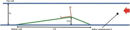
Fig.1 Schematic of the wedge in the test section (mm)

Fig.2 A typical shedding cycle for a periodically shedding cavity. Cavity growth, pinch-off, and cloud collapse are clearly visible.In the current paper, we will focus on the primary mechanism of shedding of such cavities, propagating bubbly shock waves

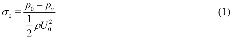
Flow properties at the inlet of the test section were measured to calculate the inlet cavitation number.Static pressure at the wedge apex and at mid-cavity was measured for all the cases. Details of the measurement procedure, equipment, and high-speed cinematography can be found in Refs.[9] and [18]. X-ray densitometry is based on the principle of Beer-Lambert’s law of attenuation of ionizing radiation. The X-ray densitometry system used in the present study had a source capable of 433 mA at 150 kV, and the imaging system comprised of an image intensifier coupled with a high-speed camera (Vision Research Phantom V9.0).By shooting an X-ray beam into the partial cavity with vapor, the void fraction flow field can be determined by analyzing the attenuated signal of the cavity. From the void fraction field, one can track interfaces such as shock waves, cavities, and shed vapor clouds. A detailed description of the method can be found in Ref.[10].
2. Bubbly shock as a mechanism of shedding
[9] and [19] studied partial cavity shedding mechanisms on wedge by varying inlet cavitation number, to study shedding behavior at different conditions. They observed that stable cavities began to shed with a very small change in the inflow pressure,and that the transition regime was narrow. In the transition regime, which was characterized by cavity pinch-off from the rear portion of the cavity, the dominant mechanism was that of a re-entrant liquid flow. In addition to the liquid re-entrant flow, transitory cavities also exhibited another mechanism of shedding, which was characterized by a propagation void fraction discontinuity as thick as the cavity. The periodicity of these transitory cavities was not well defined. For further information about transitory cavity, refer to Refs.[9] and [20].
With a further reduction in the inlet pressure, the cavities exhibited well-defined periodicity, pinching off from the wedge apex. Figure 2 shows a high-speed video time-series of a periodically shedding cavity.Cavity begins to grow from the wedge apex to attain its maximum length, upon which a propagating front begins to move upstream. The front reaches cavity apex, causing the cavity to pinch-off completely. Shed vapor rolls up as cloud to collapse downstream simultaneous when a new cavity begins to grow, repeating the process.
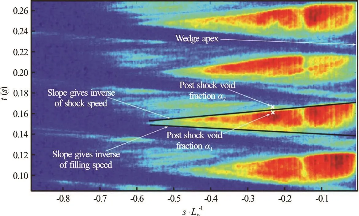
Fig.4 Measurement of shock speed by plotting the variation of void fraction with time along a line parallel to the wedge surface at a normal distance of 2 mm from the wedge surface. Positive slopes represent shocks and negative slopes cavity growth.Also indicated are the pre-shock and post-shock void fraction, and apex location
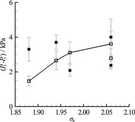
Fig.5 Comparison of predicted and measured pressure rise across the shock for different cavitation numbers. Solid symbols represent measured pressure difference and open symbols predicted pressure rise
Upon examination with X-ray densitometry, the dominant mechanism observed was that of a propagating discontinuity as thick as the cavity, as observed occasionally on transitory cavities. Figure 3 shows the X-ray densitometry based instantaneous void fraction flow fields for a shedding cycle. Presence of a propagating discontinuity in void fraction propagating upstream is clearly seen in Fig.3(d). The rest of this paper will focus on the properties of these propagating discontinuities, and their sensitivity to different flow parameters.
2.1 Bubbly shock properties
Propagating discontinuities in void fraction can be identified as bubbly shock waves if they obey underlying bubbly flow relations. References [9] and [20]discusses these in detail, but a few important aspects will be considered here. Based on X-ray densitometry measurements, instantaneous spanwise averaged void fractions are found to take values close to 0.8. At such values of void fractions, the speed of sound of these bubbly mixtures can drop to very low values (lower than the free stream speed), making the flow susceptible to shocking. Hence, the observance of these propagating bubbly shock waves are likely. A detailed description of the sonic properties of vapor mixtures are discussed in Refs.[11] and [12].
By applying mass and momentum conservations across the shock, ignoring bubbly dynamics, one can obtain the following relationship for shock speed

HereSU refers to the shock speed in the laboratory reference frame, p, refers to the static pressure, α,refers to the void fraction, andLρ, liquid density.The subscripts “1” and “2” refer to pre- and post-shock state respectively. By using X-ray densitometry measurements, void fraction values upstream1α and downstream of the shock2α, and shock speedSU can be measured. By plotting time variation of void fraction along a line parallel to the wedge surface (e.g., at a distance of 2 mm normal from the surface), shock properties can be determined,as shown in Fig.4.
By measuring the pressure within the cavity, the validity of the previous equation can be determined for the specific case of shock-induced shedding.References [9] and [20] discusses the details of the pressure measurement. From the measured properties,pressure rise across the shock can be estimated and compared with pressure rise expected based on Eq.(2).Figure 5 shows the expected and measured value of the pressure rise across the shock. Moreover, the observed flow features satisfy the relations of a propagating bubbly shock waves to a reasonable extent.This suggests the importance of compressibility of the bubbly mixture in determining the shedding dynamics.Before we discuss what aspects of compressibility are important, kinematics of these bubbly shocks is discussed first.

Fig.6 Schematic of two mechanism of shedding, re-entrant liquid jet (a)-(c), and a propagating bubbly shock (d)-(f). Expanded view of the flow at the shock vicinity near cavity closure is shown in red
2.2 Kinematics of observed bubbly shocks
Understanding the kinematics of these propagating bubbly shock waves are essential to control their behavior. In order to understand the kinematics of the bubbly shock waves, it will be beneficial to compare them with the kinematics of re-entrant liquid flow. Figure 6 shows the two mechanisms and their sub-steps. Primary differences in the shedding mechanisms are (1) transition from aft shedding to leading edge shedding, (2) Presence of a propagation discontinuity as thick as the cavity, which can also be interpreted as thick liquid flow back into the cavity, and (3)Insensitivity of the propagating discontinuity to presence of obstacles (discussed later). Figures 6(a)-6(c)represents a re-entrant flow mechanism. Such a mechanism is possible due to kinematics of a separated flow sustaining a constant pressure cavity. References [9]and [20] using free-stream line potential flow theory show that the presence of a re-entrant flow is possible when there is a stagnation point at the aft of the cavity.In such a scenario, the liquid flowing into the cavity can produce a pinch off, and the thickness of the liquid flow is smaller than the cavity thickness. For the re-entrant flow to be as thick as the cavity itself,the interface streamline has to turn aroundo180 with a radius of curvature of close to zero. This would result in low pressure which would be closer or smaller than the cavity pressure, thereby resulting in cavitation. Also, there has been no report on the presence of a re-entrant flow as thick as the cavity.
The kinematics of the bubbly shock propagation are different, as shown in Figs.6(d)-6(f). The transition in mechanisms happens abruptly with small changes in pressure and it also occurs in the asymptotic portion of the cavity length versus cavitation number curve, shown in Refs.[9] and [20]. This means that the cavity grows in length instantaneously before being arrested. Such an abrupt change would lead the interfacial liquid flow to slow down abruptly producing an increase in pressure. Such sudden changes in fluid properties can result in the production of a“water hammer” like discontinuity that propagates into the cavity. In addition, the collapse of the shed cloud can also produce a strong pressure disturbance to initial cavity collapse. Once initiated, such a pressure wave faces the consequence of reduced speed of sound within the cavity, resulting in a shock wave.Once formed, the moving shock drags the liquid downstream as in propagates into almost stationary flow within the cavity, as shown in red in Fig.6.
3. Interaction of bubbly shocks with obstacles
Placing obstacles in the closure region of shedding partial cavities have been found to be effective in arresting cavity shedding due to re-entrant jets, as reported by Ref.[19]. Reference [20] found that presence of obstacles in the path of propagating bubbly shocks results in wave interactions in the cavity that provided insights on shock formation and interactions. In this section we will briefly summarize the findings of interaction of a propagating bubbly shock waves with obstacles.
3.1 Bubbly shock properties
Due to low void fractions in the cavity, speed of sound within the cavity can be close 3 m/s to 5 m/s(half or less of the free stream speed used in studies)as discussed in Refs.[11] and [16]. Recirculating region formed at cavity closure can experience this local drop in speed of sound, once the cavity length crosses the obstacle. Since the obstacle is in the region of recirculation, an oblique shock wave forms to aid the recirculating flow to cross the obstacle. This is different from the propagating normal shock wave that results in shedding. This is shown in Figs.7(a) and 7(b). Figure 7(b) also shows the interaction of the oblique shock wave with the expansion fan that exists in the cavity. It should be noted that this expansion is a result of the propagating shock being reflection back as an expansion from the wedge apex.
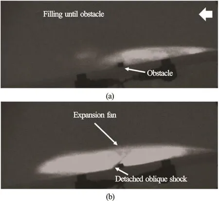
Fig.7 Cavity dynamics in the presence of an obstacle during the filling phase of the cycle for U0=8 m/s and σ0 = 1.85 ± 0 .1
3.2 Interaction of normal shock waves with obstacle
When maximum cavity length in a given cycle is significantly long to grow past the obstacle, propagating bubbly shock wave at cavity closure moves along the cavity, interacting with the obstacle. Figures 8(a) and 8(b) show the interaction of such normal shock wave with the obstacle. Once the normal shock wave crosses the obstacle, the wake of the obstacle is filled with vapour. This could be due to the cavitation of the re-entering liquid drawn by the shock as it moves into a vapour filled cavity, as explained before in Fig.6 in red or due to the rarefactions waves produced by the passage of shock over a sharp edge.The recirculation zone present at the aft of the obstacle transitions into an almost stationary mass of bubbly fluid once the void fraction values drop below a certain value. This results in the disappearance of the oblique shock (that was seen in Fig.7(b)) because of the absence of the re-entrant flow.
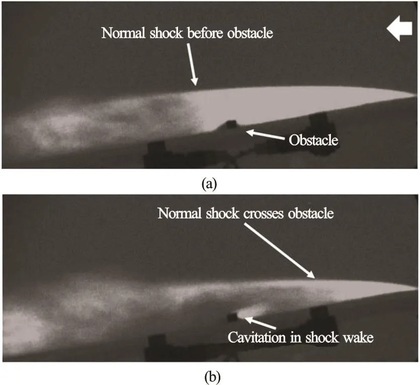
Fig.8 Cavity dynamics in the presence of an obstacle during the collapse phase of the shedding cycle for U 0=8 m/s and σ 0 = 1.85 ± 0 .1
3.3 Interaction of normal shock waves with oblique shock waves
For smaller cavity lengths and higher cavitation number, the interaction of the stationary oblique shock and the propagating normal shock is feasible. One such interaction is shown in Figs.9(a) and 9(b). For this case the cavity length was such that the detached shock occurrence due to changes in void fraction values near the obstacle and the initiation of a propagating bubbly shock occurred very close to each other in time. This can be visualised in Fig.9(b) where the complex interaction of the shock waves and the expansion fans can be seen.
More information on the kind of interactions between the waves can be found in Ref.[21].
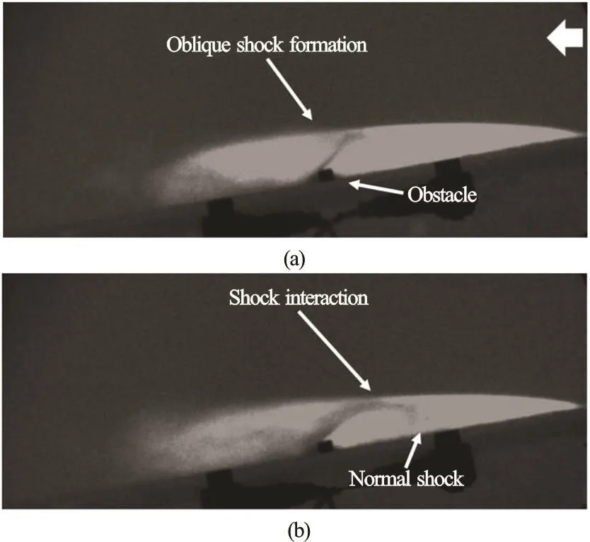
Fig.9 Shock-shock interaction U0=8 m/s and σ0=1.94±0.1
4. Sensitivity to cavity mixture properties
4.1 Dissolved gas content
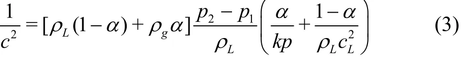
From the previous section it is evident that the observed mechanism of shedding caused by a propagating bubbly shock depends on the compressibility of the mixture. Specifically, the speed of sound in the mixtures plays a significant role in the onset of this mechanism. Reference [9] showed that occurrence of bubbly shocks occurs when the cavity Mach number based on the throat speed increases beyond a threshold value. Upon examining the expression for speed of sound given by Eq.(3), it can be inferred that the dissolved gas content and cavity pressure can play an important role.
Reference [18] studied the effect of non-condensable dissolved gas content on the shedding dynamics induced by propagating bubbly shock waves. Figure 10 shows the measured bubbly shock propagation speed in the laboratory reference frame based on X-ray densitometry measurements, for three different dissolved oxygen contents. Measured shock speed did not change significantly, suggesting no dependence on the dissolved oxygen content for the shock properties over parameter range studied in Ref.[18]. Outgassing process in the cavity is not as important as the vapor generation processes, as discussed in the next section.
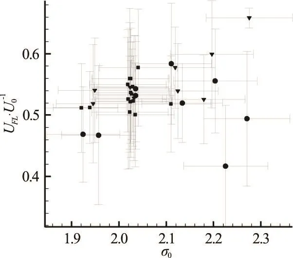
Fig.10 Measured shock propagation speeds for various inlet cavitation numbers for different free-stream dissolved oxygen content. Shock speeds were not influenced by dissolved non-condensable gas content. ▼DO< 5 0%, ■ - D O ~5 0%, ● - DO>50%
4.2 Non-condensable gas injection
Reference [18], in addition, also studied the effect of non-condensable gas injection into the cavity,in altering the shedding dynamics of the cavity. They performed the study on the same model as Ref.[9],which was discussed in the previous section. This facilitated a direct comparison of the effect of non-condensable gas injection. By injecting non-condensable gas from the wedge apex and at a location slightly downstream of the wedge apex for a range of flow rates, they found that shedding dynamics changed significantly at higher gas flow rates (that were still small compared to vaporization rates). Notably, injection of non-condensable changed the shock propagation speed. Figure 11 shows the variation of shock propagation speed with non-condensable gas injection for a periodically shedding cavity. Injection rate QIwas non-dimensionalized based on the maximum vapor production rate obtained from a periodically shedding cavity with no-injection, obtained from X-ray densitometry measurements. Reference [18] discusses the methodology and procedure for estimating the maximum vapor production,maxVQ .
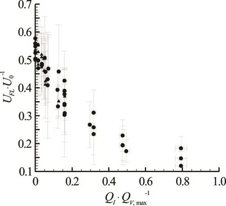
Fig.11 Measured shock propagation speeds for a shedding cavity with non-condensable gas injection at different rates and locations. For the case of apex injection (▲),shedding completely ceases at higher flow rates, while for mid-cavity injection (●) propagation speed decreases
While at lower gas injection rates, injection process alters the shock propagation speed, the effect becomes prominent as the injection rate increases.Location of gas injection did not play a significant role in changing the behavior of the shock propagation speed with non-condensable gas injection. Examination of the speed of sound expression provides insights into the physical processes that dictate the above observations. Two important factors that influence speed of sound, and hence shock formation and dynamics, are the initial void fraction in the cavity,αcore, and the cavity static pressure, pcav. The process of non-condensable gas injection can alter both of these quantities. Figure 12 shows the variation of cavitation number within the cavity, showing an increase in cavity pressure with increasing injection rates. This is due to the nature of injection process itself, for higher flow rates need a higher back pressure, and hence total head of the injected fluid.This would result in increasing the cavity pressure locally.
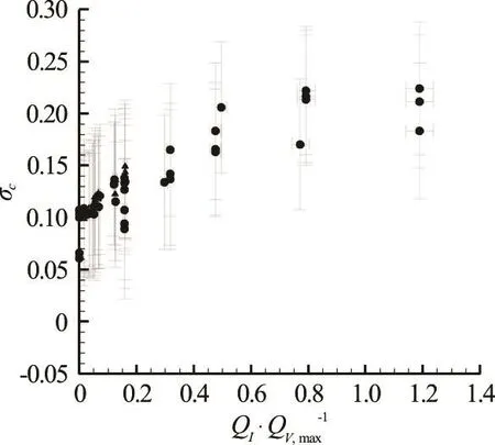
Fig.12Cavitation number at wedge apex (▲)and mid-cavity(●)for a range of non-condensable gas injection rates.Increase in cavity staticpressure duetoinjection process can be clearly seen
Figure 13showsthevariation of thesecond important parameter that dictatesshock propagation speed,void fraction within the cavity,coreα.Upon examination, it can be seen that the absolute value and variation ofcoreαdecreaseswith injection rate,which is very counter intuitive, as one might assume injection of non-condensablegascan only increase void fraction within thecavity.However,for apex injection,theinjection processaltersthe separation shear layer and pressure at suction peak near apex,hence changing the natural cavitation vapor production rate.
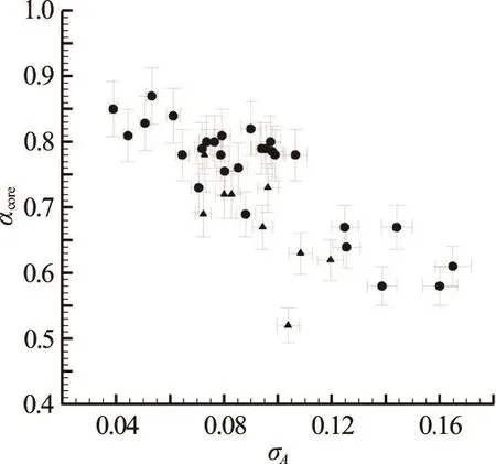
Fig.13 Void fraction upstream of the shock,coreα, for different non-condensable gas injection rates at wedge apex (▲)at fixed 0σ, and with no gas injection (●) and change in 0σ. Decrease in the core void fraction value is attributed to the influence of the injected non-condensable gas on the formation of vapor near the suction peak and in the shear-layer at the wedge apex
It should alsobementioned that propagating bubbly shocksdiscussed in thecurrent paper were planar. There are other situations when the topology of the propagating shock wave can be three-dimensional. Some examples include mechanism of cavity growth arrest due to shed cloud collapse as discussed in Ref.[22], and cavitation collapse in a wake behind a bluff body which is characterized by non-planar shock fronts. The nature of shock topology depends on the localvoid fraction gradients,underlyinggeometry,among other things.
5. Conclusions
Transition from stable to shedding partial cavities can have many adverseeffects.Apart from the classical liquid re-entrant flow, propagation of bubbly shock waves can also be the dominant mechanism of shedding.High valuesof void fraction result in altering thecompressibility of thebubbly flow, by changing the local speed of sound, thereby making the flow susceptibletoshocking.Experimentally measured properties of such bubbly shocks satisfy those predicted by simpleconservation lawsthat ignored bubble dynamics. Properties of the shock waves can bemanipulated by non-condensablegasinjection which alters the bubbly flow within the cavity. From shock dynamicsperspective,interaction of shock waves with obstacles placed in their path reveal the kinematicsof shock wave propagation within the cavity.
Acknowledgements
This work was supported by the Office of Naval Research (Grant No. N00014-14-1-0292) under program manager Dr. Ki-Han Kim. The authors would like tothank Anubhav Bhatt for hisassistance in preparing the manuscript.
References
[1]Franc J. P., Michel J. M. Fundamentals of cavitation [M].Dordrecht, The Netherlands: Springer, 2006.
[2]Hutton S. P., Furness S. P. Experimental and theoretical studies of two-dimensional fixed-type cavities [J]. Journal of Fluids Engineering, 1975, 97: 515-522.
[3]Lush P. A., Skipp S. R. High speed cine observations of cavitating flow in a duct [J]. International Journal of Heat and Fluid Flow, 1986, 7(4): 283-290.
[4]Le Q., Franc J. P., Michel J. M. Partial cavities: Global behavior and mean pressure distribution [J]. Journal of Fluids Engineering, 1993, 115(3): 243-248.
[5]De Lange D. F., De Bruin G. J. Sheet cavitation and cloud cavitation,re-entrant jet and three-dimensionality [J].Applied Scientific Research, 1997, 58(1-4): 191-114.
[6]Callenaere M., Franc J. P., Michel J. M. et al. The cavitation instability induced by thedevelopment of a re-entrant jet [J]. Journal of Fluid Mechanics, 2001, 444:223-256.
[7]Laberteaux K. R., Ceccio S. L. Partial cavity flows. Part 1.Cavities forming on models without spanwise variation [J].Journal of Fluid Mechanics, 2001, 431: 1-41.
[8]Gopalan S., Katz J. Flow structure and modeling issues in the closure region of attached cavitation [J]. Physics of fluids, 2000, 12(4): 895-911.
[9] Ganesh H., Mäkiharju S. A., Ceccio S. L. Bubbly shock propagation as a mechanism for sheet-to-cloud transition of partial cavities [J]. Journal of Fluid Mechanics, 2016,802: 37-78.
[10] Mäkiharju S. A., Gabillet C., Paik B. et al. Time-resolved two-dimensional X-ray densitometry of a two-phase flow downstream of a ventilated cavity [J]. Experiments in fluids, 2013, 54(7): 1-21.
[11] Crespo A. Sound and shock waves in liquids containing bubbles [J]. Physics of Fluids, 1969, 12(11): 2274-2282.
[12] Brennen C. E. Fundamentals of multiphase flow [M].Cambridge, UK: Cambridge University Press, 2005.
[13] Gnanaskandan A., Mahesh K. Large eddy simulation of the transition from sheet to cloud cavitation over a wedge[J]. International Journal of Multiphase Flow, 2016, 83:86-102.
[14] Budich B., Schmidt S., Adams N. A. Numerical investigation of condensation shocks in cavitating flow [C].Proceedings of the 31st Symposium of Naval Hydrodynamics. Monterey, California, USA, 2016.
[15] Wu X., Etienne M., Chahine G. L. An experimental study of sheet to cloud cavitation [J]. Experimental Thermal and Fluid Science, 2017, 83: 129-140.
[16] Shamsborhan H., Coutier-Delgosha O., Caignaert G. et al.Experimental determination of the speed of sound in cavitating flows [J]. Experiments in Fluids, 2010, 49(6):1359-1373.
[17] Tomov P., Khelladi S., Ravelet F. et al. Experimental study of aerated cavitation in a horizontal venturi nozzle[J]. Experimental Thermal and Fluid Science, 2016, 70:85-95.
[18] Mäkiharju S. A., Ganesh H., Ceccio S. L. The dynamics of partial cavity formation, shedding and the influence of dissolved and injected non-condensable gas [J]. Journal of Fluid Mechanics, 2017, 829: 420-458.
[19] Kawanami Y., Kato H., Yamaguchi H. et al. Mechanism and control of cloud cavitation [J]. Journal of Fluids Engineering, 1997, 119(4): 788-794.
[20] Ganesh H. Bubbly shock propagation as a cause of sheet to cloud transition of partial cavitation and stationary cavitation bubbles forming on a delta wing vortex [D].Doctoral Thesis, Ann Arbor, USA: University of Michigan, 2015.
[21] Liepmann H. W., Roshko A. Elements of gasdynamics [R].Courier Corporation, 1957.
[22] Ganesh H., Wu J., Ceccio S. L. Investigation of shedding dynamics on NACA0015 hydrofoil using time-resolved X-ray densitometry [C]. Proceedings of the 31st Symposium of Naval Hydrodynamics. Monterey, California, USA,2016.
杂志排行

水动力学研究与进展 B辑的其它文章
- A sharp interface approach for cavitation modeling using volume-of-fluid and ghost-fluid methods *
- On the numerical simulations of vortical cavitating flows around various hydrofoils *
- Experimental measurement of tip vortex flow field with/without cavitation in an elliptic hydrofoil *
- The effect of water quality on tip vortex cavitation inception *
- Novel scaling law for estimating propeller tip vortex cavitation noise from model experiment *
- Simulation of cavitation induced by water hammer *