RelationshiP Between Corrosion Level of Steel Bar and Diameter of Corroded Sensing Steel Wire in Wireless Sensor
2015-11-21XuGaowa许高娲WuJin吴瑾WangZhe王喆ChenZhen陈镇
Xu Gaowa(许高娲),Wu Jin(吴瑾),Wang Zhe(王喆),Chen Zhen(陈镇)
College of Aerospace Engineering,Nanjing University of Aeronautics and Astronautics,Nanjing 210016,P.R.China
RelationshiP Between Corrosion Level of Steel Bar and Diameter of Corroded Sensing Steel Wire in Wireless Sensor
Xu Gaowa(许高娲),Wu Jin(吴瑾)*,Wang Zhe(王喆),Chen Zhen(陈镇)
College of Aerospace Engineering,Nanjing University of Aeronautics and Astronautics,Nanjing 210016,P.R.China
A kind of wireless sensor was previously developed,which is powered and transmit signals wirelessly instead of using an electrical connection to the embedded reinforcement.Based on this technique,the relationship between diameters of corroded sensing steel wires and corrosion levels of steel bars is established by experiments. Quadratic function is utilized to fit the experiment results,and the correlation coefficients are all larger than 0.95. Estimated corrosion levels of commonly used steel bars are given for different diameters of corroded sensing steel wires fractured due to corrosion.
reinforcement;corrosion;wireless sensor;resonant frequency;sensing steel wire;stress
0 Introduction
Reinforcement corrosion is one of the major causes of failure and damage of reinforced concrete structures.It has received an increasing attention in recent years because of its widespread occurrence in certain types of structures and high repair costs[1,2].In the past years,non-destructive methods have been developed to effectively assess rebar corrosion susceptibility in existing structures.Thanks to its simplicity,methods to establish rebar corrosion state in concrete is the measurement of corrosion potential.However,this method can not provide information about the kinetics during rebar corrosion and therefore it can not indicate rebar corrosion rate[3,4].Another electrical chemistry technique uses linear polarization resistance,but it cannot detect the actual loss in steel cross section which at present only can be assessed by direct visual observation[5]. Although electrical potential and linear polarization measurement are the most commonly known techniques,they are merely qualitative.Moreover,the data from these methods are often unreliable and unstable.
It is necessary to establish a reliable and stable methodology to represent the corrosion level in concrete structures.Wireless sensors can be an ideal choice for the wireless,low cost,and nondestructive features.A wireless detection method of reinforcement corrosion based on LC circuit was put forward at the University of Texas.It could just detect corrosion of steel bar qualitatively and some crucial problems remained unresolved,such as coupling efficiency,encapsulation and arrangement[6,7].Therefore,we have developed a kind of wireless sensor for monitoring corrosion of steel bars,which is passive,low cost,and nondestructive[8].The wireless sensor is based on LC circuit technically with an external switch replaced by a sensing steel wire.Sensing steel wire is put at the same environment as steel bar.Erequency of LC circuit will change when the sensing steel wire fractures due to corrosion. Therefore,the relationship between sensing steel wires fractured due to corrosion and corrosionlevels of steel bars needs to be inferred from experiment primarily,then determine the relationship between different frequencies and corresponding corrosion levels of steel bars can be determined.Shinji et al.[9]concluded that corrosion rates of the wire increased while decreasing diameter(φ0.1—1.0 mm)in NaCl solutions at p H 5.9 and p H 2.5,respectively.However,they only investigated the relationship between corrosion rates of the wires and diameters.
The objective of this paper is to elaborate the relationship between the diameters of sensing steel wires used in the wireless sensors and corrosion levels of steel bars in order to detect the corrosion levels of steel bars precisely.
1 Mechanism of Wireless Corrosion Sensor
As shown in Eig.1,the whole sensor system includes a reader and a resonant sensing circuit. The sensing circuit on the right in Eig.1 is composed of the inductance component(L),the capacitance components(C)and an external switch. In Eig.1,Zinis the input impendence,and M the mutual coefficient.Therefore,the sensing circuit can be idealized as a LC circuit.The resonant frequency of the circuit will shift with a change in capacitance,which can be realized by connecting a second capacitor to the circuit via an external switch[6].When the external switch is closed,the circuit resonate at its initial frequency is
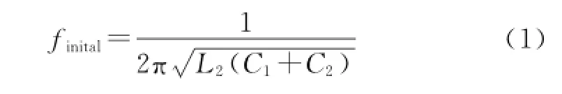
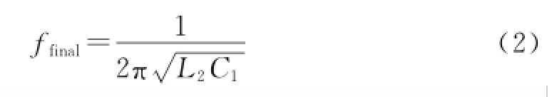
When the external switch is open,the circuit resonate at its final frequency is
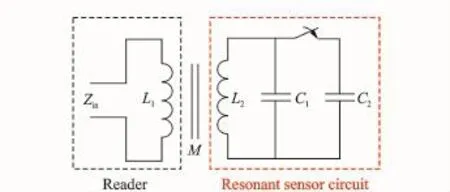
Eig.1 Simplified schematic of sensor
Eig.2 shows that the measured initial resonant frequency of the sensor is smaller than its final resonant frequency.When the external switch is open,the final resonant frequency will shift to an appreciably higher value.
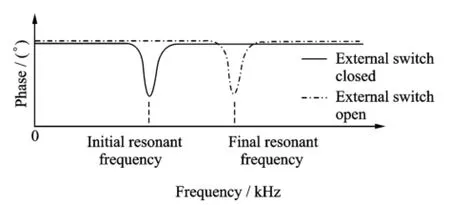
Eig.2 Principle of impedance response
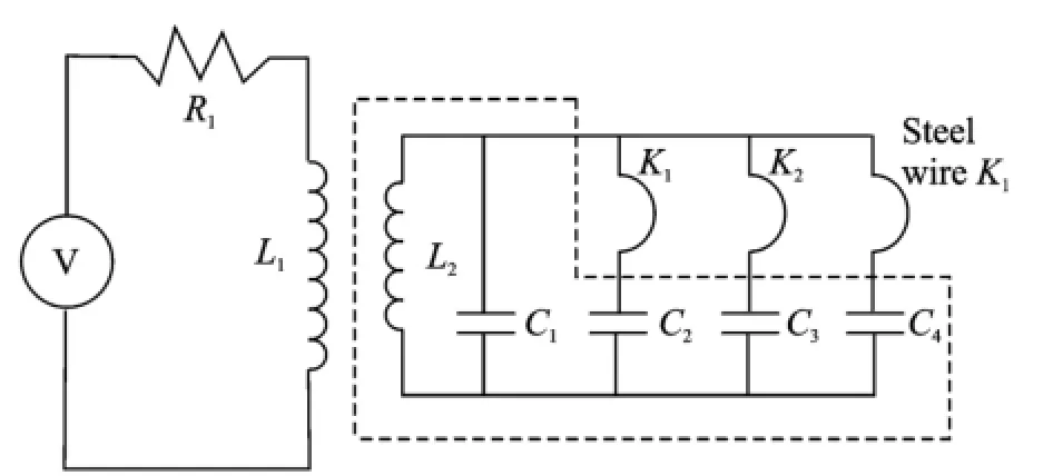
In the paper,the external switch is replaced by a sensing steel wire K which is put out of the sealed portion of the sensor,as shown in Eig.3. R1is a resistance in reader sensor.The intact state of the sensing steel wire corresponds to the case of closing the external switch mentioned above,and the fractured state of it corresponds to the case of opening the external switch.

Eig.3 Refined schematic of sensor for monitoring corrosion of reinforcement
The sensor is embedded in the concrete and the wire is exposed to the same environment conditions,i.e.the same corrosive environment,as the steel reinforcement.As the corrosion process begins in the sensing steel wire and in the reinforcement simultaneously,both the cross-sectional areas decrease.Since the diameter of the wire is much smaller than that of steel reinforcement,the wire will fracture due to corrosion.Therefore,the corrosion detection to the reinforcing steel can be performed by reading the resonantfrequency data of the sensor[8].
An important consideration when designing an embedded sensor is how to power the device. Eor wired sensor networks,powering the device is simply a matter of a few additional wires,or even combining power and data lines into a single two-wire system.Typically,wireless devices rely on battery power.Depending on the needs of the device,batteries can be relatively inexpensive or rather costly.Also,batteries have a finite lifetime.An alternative is to use"unpowered"or passive sensors.Strictly speaking,the devices are powered by energy from the electric or magnetic field.The sensor were made to rely on wireless communication,making the sensors easy to place,and not to include a battery within the sensor,so that the life of the sensor would not be limited by the life of the battery.
Another significant consideration is test accuracy of the developed sensors.Within the context of structural health monitoring,the sensors may be subjected to large temperature variations,rough handling,vibration during concrete placement,and potential exposure to harsh environments because corrosion of steel bars is a stochastic phenomenon in nature.In order to guarantee the test accuracy(such as above 85%realiability),based on the genetic particle swarm optimization algorithm,the system reliability for corrosion-monitoring and sensors cost act as constraint condition and objective function,respectively,the optimization placement of wireless sensors has been proposed previously[10].
2 Wireless Sensor for Monitoring Different Corrosion States
As previously stated,once the sensing steel wire fractures,it can indicate one state of reinforcement corrosion.To detect different corrosion states[8,11],different diameters of sensing steel wires are used to establish the prototype sensors to serve as the state switches.Eig.4 illustrates the circuit of the wireless sensor for monitoring three discrete states of corrosion.The resonant frequency will change when each wire fractures due to corrosion,and different diameters of steel wires fractured due to corrosion correspond to corrosion levels of steel bars.Therefore,the sensor can indicate four corrosion states of steel bars,such as non-corrosion,slight corrosion,obvious corrosion and severe corrosion.In order to obtain the accurate corrosion information of steel bars,the relationship between the diameters of the sensing steel wires fractured due to corrosion and the loss of the weight of reinforcement need to be established by experiments.
Eig.4 Circuit for sensor with three switches
3 ExPeriment Program
3.1 Materials
Seven different diameter ribbed bars were selected,and diameters varied from 10 to 22 mm. The chemical composition of steel bars in this experiment was shown in Table 1.Meanwhile,sensing steel wires were made of the same material as that of steel bars for the corrosive consistency in the reinforced concrete structures,and steel wire diameters were 0.4,0.6,0.8,1.2,1.6,1.8 and 2.3 mm,respectively.
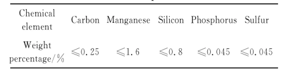
Table 1 Chemical comPosition of steel bars
The steel bars consist of two groups.The control group was not loaded,and another group was loaded with 0.6 of stress ratio(relative to design strength,i.e.f=0.6fy=0.6×360 MPa= 216 MPa),while the sensing steel wires were not loaded.
Sensing steel wires and steel bars were placed simultaneously in the saturated Ca(OH)2solution in order to simulate concrete pore solution in practical concrete structures,and the p H value of the concrete pore solution was around 12 or 13. Additionally,salt was added in the amount of 3.5%to simulate seawater environment.Wetting and drying cycles were applied in order to accelerate the corrosion process of sensing steel wires and steel bars.
3.2 Design of sustained loading
The setup for sustained loading test was shown in Eig.5.In order to guarantee minimal sufficient strength and stiffness for the experimental frame,the cross sections of the frame were designed as 55 mm×50 mm and 55 mm× 35 mm,respectively.The experimental frame worked as a cohesive whole,and steel bars could be arranged via holes.Nuts were used to tighten the screw thread at the ends of steel bars before loading.As deformations of the springs on the surface of steel bars corresponded to the load of steel bars,the vernier caliper was used to measure deformations in order to guarantee load accurately.
The parameters of disk springs from specification of AQSIQC GB/T 1972-2005(China)are listed in Table 2.Deformations of the springs with different diameter steel bars were calculated as shown in Table 3.As a consequence,the external load could be controlled easily and measured accurately by the deformations of the disk springs.
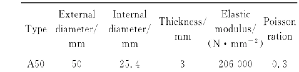
Table 2 Disk sPring Parameters
Tensile stress was exerted by nuts at the end of steel bars after steel bars were fixed on the loading test setup.The exerted stress was 7% larger than the design stress because of the stress relaxation of steel bars.The deformations of disk springs with different diameters of steel bars were measured once a day for ensuring the proper stress of steel bars.
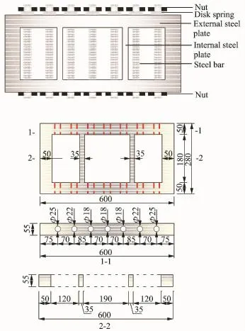
Eig.5 Details and dimensions of setup for sustained loading
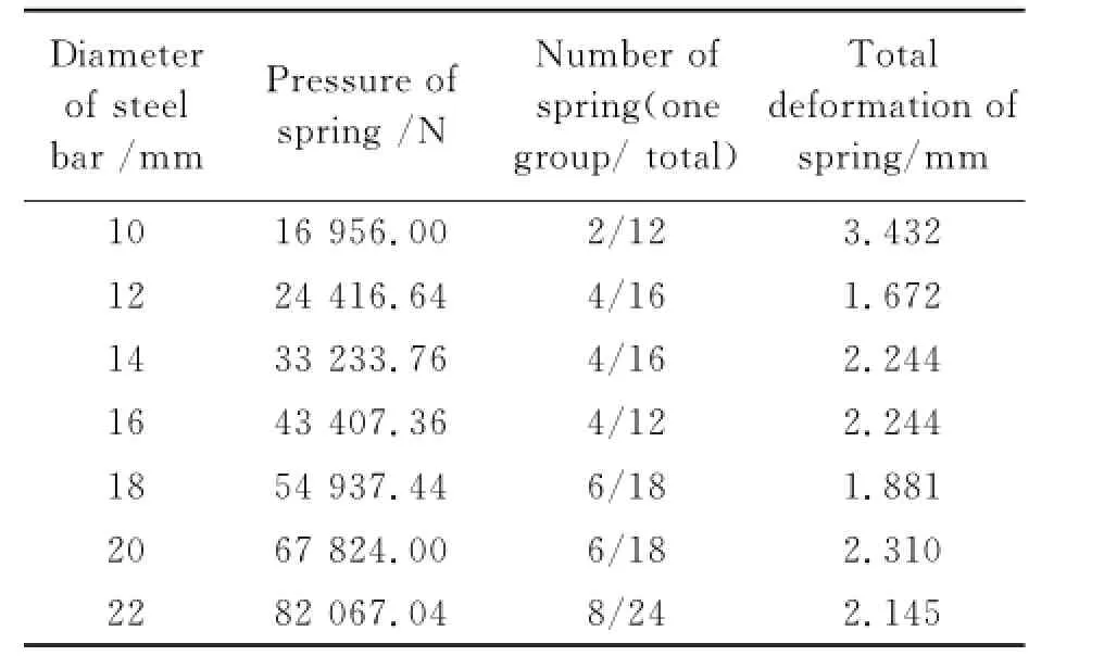
Table 3 Deformations of sPring with different diameter steel bars
3.3 Measurement of corrosion level of steel bar
The line mass of steel bars(W1)was measured before the tensile stress was exerted.The corrosion state of sensing steel wires was observed using wetting-drying cycle twice a day until the sensing steel wire fractured.After the sensing steel wire fractured,steel bars with dif-ferent diameters were taken out of loading test setup and were all cut into 100 mm long specimens.Then the ends of specimens were ground,and the rust on the surface of steel bars was removed with 12%concentration dilute hydrochloric acid,then the line mass of steel bars(W2)was measured.The mass loss of steel bars can be estimated
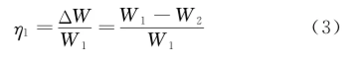
where W1is line mass of non-corrosion steel bar W2the line mass of corrosion steel bar after removing the rust.
4 Results and Analysis
The relationship between diameters of sensing steel wire fractured due to corrosion and corrosion levels of steel bars is shown in Eig.6.
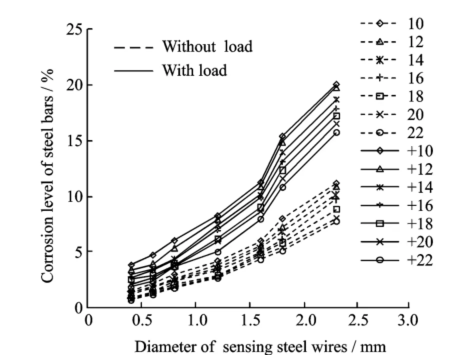
Eig.6 Diameters of sensing steel wires versus corrosion levels of steel bars
Erom Eig.6,it is obvious that the corrosion levels of steel bars with load are much larger than that without load.Eor instance,when the sensing steel wire with 0.4 and 2.3 mm diameter was corroded gradually and fractured eventually,the corrosion levels of 10 mm steel bars with load are 2.49 and 1.79 times,respectively,compared with that without load.Meanwhile,the corrosion levels of 22 mm steel bars increase by 1.63 and 1.03 times.Other literatures showed that corrosion levels of steel bars in the concrete with load had a great increase compared with the ones without load[12,13].Ksia˙zek even found that corrosion current density and rate of reinforcing steel tended to increase when tensile stress grew,and the potential of reinforcement corrosion decreased after loading[14].Stress corrosion can be classified into two categories:Hydrogen induced cracking and anode dissolution[15,16].The hydrogen induced cracking during the stress corrosion is a kind of cracking mainly caused by hydrogen. However,if the cathodic reaction of stress corrosion is oxygen reaction or hydrogen induced cracking is not the main progress,the corrosion progress is anode dissolution.Corrosion of steel bars with load in the paper can be classified as anode dissolution according oxygen reaction in the cathode.
The solid line in Eig.6 represents the relationship between corrosion levels of steel bars with load and diameters of sensing steel wires fractured due to corrosion.The corrosion levels of steel bars increase with the diameters of sensing steel wires.Eor instance,compared the experiment results of 2.3 and 0.4 mm sensing steel wires fractured due to corrosion,the corrosion levels of 10 and 22 mm steel bars with load increase by 4.16 and 7.32 times,respectively.The corrosion levels of steel bars depend greatly on the time when sensing steel wires fracture due to corrosion.
Eig.6 also illustrates that the corrosion level of steel bar decreases with the increase of the diameter of steel bar.Eor instance,when the 0.4 and 2.3 mm sensing steel wires fractures due to corrosion,the corrosion levels of 10 mm steel bars are 2.06 and 1.28 times as high as those of 22 mm steel bars,respectively.This is because the surface area of steel bar has an inverse proportional relationship with the diameter of steel bar when the mass of steel bar is constant(Eqs.(4,5)).Therefore,when the diameter of steel bar decreases,the surface area that contacted with corrosive environment increases,and it results in an increase of the corrosion levels of steel bars
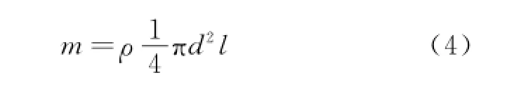
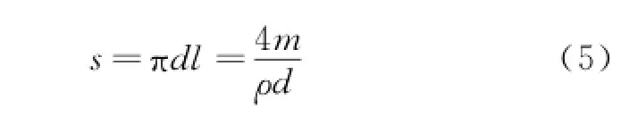
where m,ρ,d,l and s are the mass,the density,the diameter,the length and the surface area of steel bar,respectively.
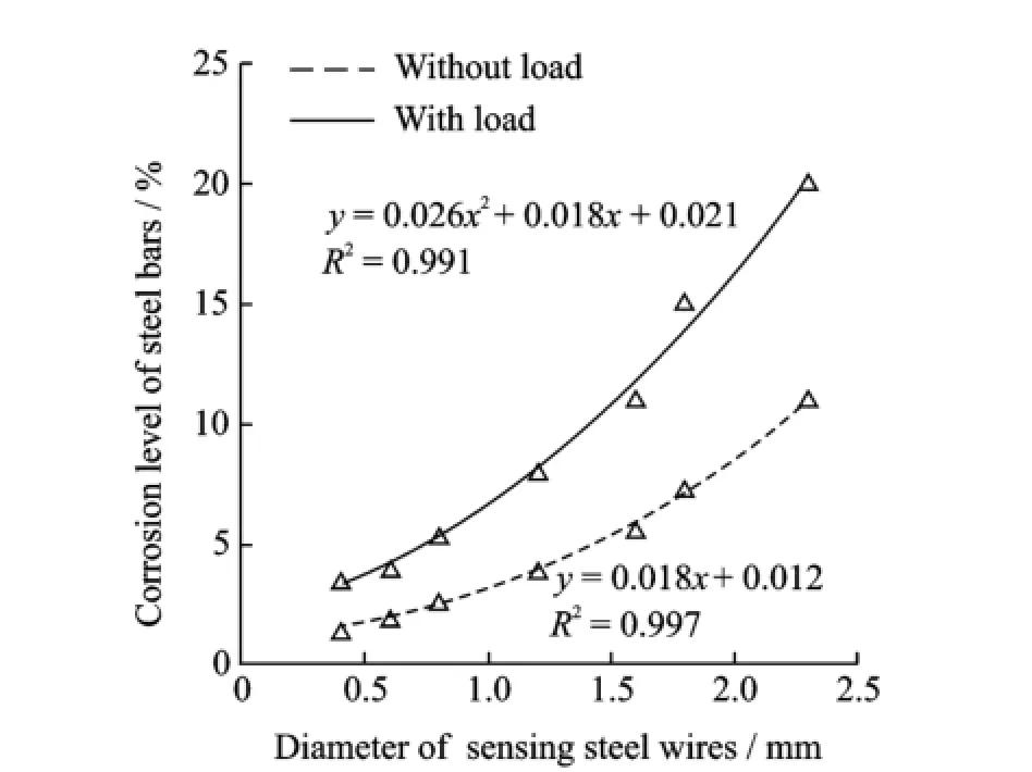
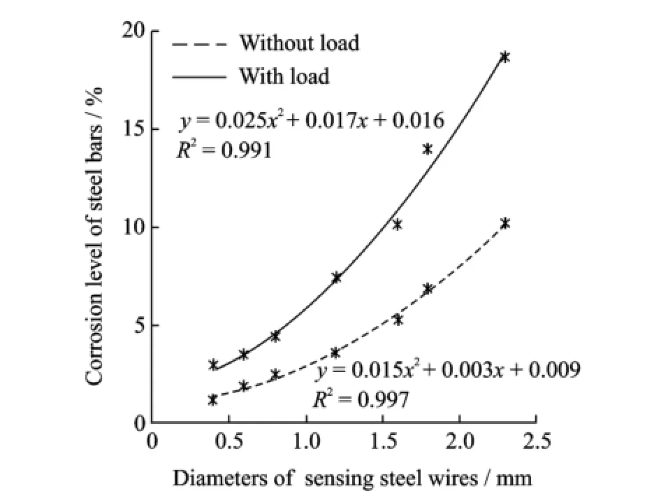
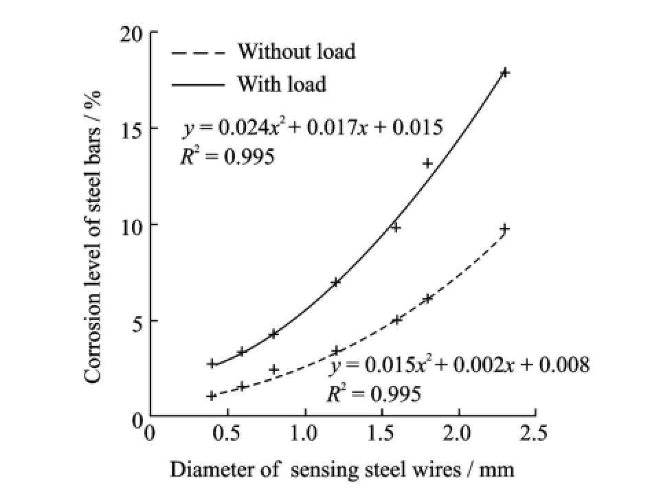
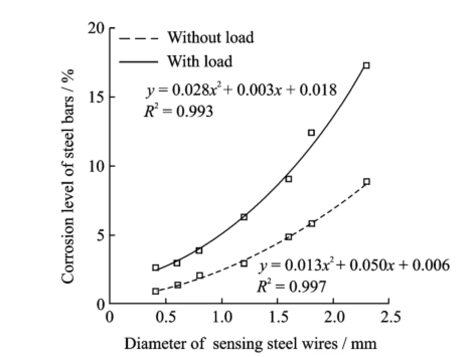
Quadratic function(y=ax2+bx+c,where y is the corrosion level of steel bar;x the diameter of sensing steel wire fractured due to corrosion)was used to fit the experimental results.The fitting results are shown in Eigs.7—13,and the correlation coefficients(R2)are all greater than 0.95.
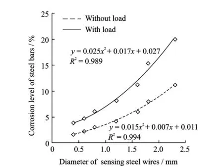
Eig.7 Results of 10 mm diameter steel bar
Eig.8 Results of 12 mm diameter steel bar
Based on the experiment results,a quantitative method is given to detect corrosion level of steel bar in concrete.Corrosion levels for commonly used diameters of steel bars in practical engineering are estimated in Table 4 according to experiment results when different diameters of sensing steel wires fracture due to corrosion.
Eig.9 Results of 14 mm diameter steel bar
Eig.10 Results of 16 mm diameter steel bar
Eig.11 Results of 18 mm diameter steel bar
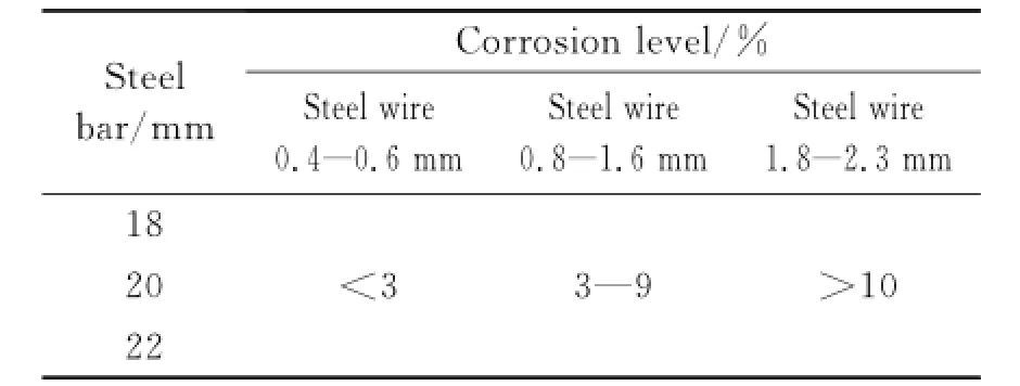
Table 4 Criteria for corrosion levels of steel bars in concrete

Eig.12 Results of 20 mm diameter steel bar
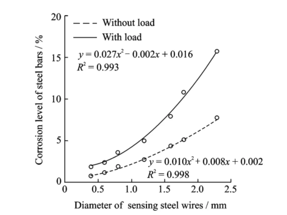
Eig.13 Results of 22 mm diameter steel bar
5 Conclusions
The wireless sensors dicussed in this paper were previously built to detect the onset corrosion in reinforced concrete structures.The functionality of two different corrosion sensor models is introduced.Experiment results illustrate that the corrosion levels of steel bars have a significant increase after loading,and it decreases with an increase of diameters of steel bars.The quantitative relationship between corrosion levels of steel bars and diameters of sensing steel wires fractured gradually due to corrosion is obtained by using quadratic function.A criterion is proposed to estimate corrosion levels of commonly used steel bars in concrete.Corrosion levels of steel bars can be obtained quantificationally by the wireless sensors.
Acknowledgement
The work was supported by the National Natural Science Eoundation of China(No.51279074).
[1] Michel A,Solgaard A O S,Pease B J,et al.Experimental investigation of the relation between damage at the concrete-steel interface and initiation of reinforcement corrosion in plain and fibre reinforced concrete[J].Corrosion Science,2013(77):308-321.
[2] Val D V,Chernin L,Stewart M G.Experimental and numerical investigation of corrosion-induced cover cracking in reinforced concrete structures[J]. Journal of Structural Engineering,2009,135(4):376-385.
[3] Qiao G,Liu T,Dai J,et al.Qualitative and quantitative sensors based on electrochemical techniques for the corrosion assessment of RC panels[J].Sensors Journal,IEEE,2012,12(6):2062-2063.
[4] Hussain R R.Underwater half-cell corrosion potential bench mark measurements of corroding steel in concrete influenced by a variety of material science and environmental engineering variables[J].Measurement,2011,44(1):274-280.
[5] Ahmad S.An experimental study on correlation between concrete resistivity and reinforcement corrosion rate[J].Anti-Corrosion Methods and Materials,2014,61(3):158-165.
[6] Simonen J T,Andringa M M,Grizzle K M,et al. Wireless sensors for monitoring corrosion in reinforced concrete members[C]//Smart Structures and Materials.San Diego:International Society for Optics and Photonics,2004:587-596.
[7] Dickerson N P,Simonen J T,Ardringa M M,et al. Wireless low-cost corrosion sensors for reinforced concrete structures[C]//Smart Structures and Materials.[S.l.]:International Society for Optics and Photonics,2005:493-503.
[8] Wu J,Wu W C.Study on wireless sensing for monitoring the corrosion of reinforcement in concrete structures[J].Measurement,2010,43(3):375-380.
[9] Shinji S,Takenori N,Nobuhiko I,et al.Corrosion rate diameter dependency of high carbon steel wire in NaCl aqueous solution[J].Kobe Steel Engineering Reports,2000,50(1):61-64.
[10]Xu Gaowa.Simulation analysis and optimal placement of wireless corrosion sensors for monitoring corrosion of reinforcement in concrete[D].Nanjing:Nanjing University of Aeronautics and Astronautics,2015.
[11]Xu G,Wu J,Wang Z,et al.Simulation on working process of wireless sensor for monitoring corrosion of steel bars[J].Journal of Nanjing University of Aeronautics&Astronautics,2013,45(2):21-24.(in Chinese)
[12]Ahn W,Reddy D V.Galvanostatic testing for the durability of marine concrete under fatigue loading[J].Cement and Concrete Research,2001,31(3):343-349.
[13]Gong Jinxin,Wang Haichao,Li Jinbo.Effect of loading on corrosion of reinforced concrete beam exposed in corroded environment[J].Journal of Southeast University:Natural Science Edition,2005,35(3):421-426.(in Chinese)
[14]Ksiᶏ˙zek M.The evaluate tendencies of corrosion process for reinforcing steel when covered with special polymer sulfur coating[J].Engineering Eailure Analysis,2014(39):1-11.
[15]Chu W Y,Gu B,Gao K.New progress in the study on stress corrosion cracking mechanism[J].Corrosion Science and Protection Technology,1995,7(2):97-101.(in Chinese)
[16]Sanchez J,Eullea J,Andrade C,et al.Stress corrosion cracking mechanism of prestressing steels in bicarbonate solutions[J].Corrosion Science,2007,49(11):4069-4080.
(Executive editor:Zhang Bei)
TU19 Document code:A Article ID:1005-1120(2015)03-0297-08
*CorresPonding author:Wu Jin,Professor,E-mail:wujin@nuaa.edu.cn.
How to cite this article:Xu Gaowa,Wu Jin,Wang Zhe,et al.Relationship between corrosion level of steel bar and diameter of corroded sensing steel wire in wireless sensor[J].Trans.Nanjing U.Aero.Astro.,2015,32(3):297-304.
http://dx.doi.org/10.16356/j.1005-1120.2015.03.297
(Received 10 Eebruary 2015;revised 20 April 2015;accepted 3 May 2015)
杂志排行

Transactions of Nanjing University of Aeronautics and Astronautics的其它文章
- Two-Dimensional Modal Curvature for Damage Detection in Plates
- Performance ImProvement Method of CFRP with Embedded OPtical Fiber
- MorPhological Undecimated Wavelet DecomPosition Fusion Algorithm and Its APPlication on Fault Feature Extraction of Hydraulic PumP
- Construction of Crack Perturbation Model and Forward Semi-analytical Model of Attached Eddy Current Sensor
- Resistance SPot Welding Method for Metal-Based Fiber Bragg Grating Sensors
- Data Fusion of MultiPle Curvature Mode ShaPes for Structural Damage Diagnosis