Performance ImProvement Method of CFRP with Embedded OPtical Fiber
2015-11-21LiuRongmei刘荣梅XiaoJunLiangDakai梁大开WangGuina王桂娜
Liu Rongmei(刘荣梅),Xiao Jun(肖 军),Liang Dakai(梁大开),Wang Guina(王桂娜)
1.College of Aerospace Engineering,Nanjing University of Aeronautics and Astronautics,Nanjing 210016,P.R.China;
2.College of Material Science and Technology,Nanjing University of Aeronautics and Astronautics,Nanjing 210016,P.R.China
Performance ImProvement Method of CFRP with Embedded OPtical Fiber
Liu Rongmei(刘荣梅)1*,Xiao Jun(肖 军)2,Liang Dakai(梁大开)1,Wang Guina(王桂娜)1
1.College of Aerospace Engineering,Nanjing University of Aeronautics and Astronautics,Nanjing 210016,P.R.China;
2.College of Material Science and Technology,Nanjing University of Aeronautics and Astronautics,Nanjing 210016,P.R.China
Optical fiber-based sensors are usually applied in structural health monitoring(SH M)as part of smart materials.The weak interface between the optical fiber and the host material will reduce the mechanical performance of the smart materials.Normally,the principal parts of the optical fibers are inorganic,while the matrix of host material is organic.These two kinds of materials can not be combined.Micro-fracture can be found in smart materials.Two methods for improving the interface are proposed.Eirstly,the influence of the interface size on the strength is studied.Secondly,interfacial treatment before embedding the optical fiber into the composite is analyzed.Compressive tests of composite laminated specimens are conducted to evaluate the proposed methods.The specimens are produced from T300 Carbon/epoxy prepreg,with different treated optical fiber embedded inside. The experimental results indicate that smaller interface size and proper treatment will strengthen the whole structure.
optical fiber;smart material;interface;carbon fiber reinforced plastics(CERP);chemical treatment
0 Introduction
Individual optical fiber or fiber networks are often applied in structural health monitoring(SHM)[1-2],thanks to their advantages,including capability of embedded inside composite and immunity to electromagnetic interference.Recently,intelligent structures have been developed with optical fiber sensors embedded inside composites[3-6].
The diameter of the optical fiber is usually 100μm to 200μm,while reinforcing fibers are 5μm to 10μm in general.Therefore,the embedded optical fiber will influence the mechanical performance of the host material.The interaction between a composite material and optical fiber sensors is very significant and depends on many factors[7].
The mechanical effects of embedded optical fiber(OE)on smart materials have been a research concern for years[8-10].Lee et al.[10]revealed that the optical fiber had no significant effect on static properties of composite specimen. However,significant reduction of fatigue life was observed.Hadzic et al.[11]pointed out that approximately 33%reduction in failure load was observed if the composite laminates had more densely embedded OE.Surgeon and Wevers[12]reported the similar observation.However,they emphasized that interface played a role in structural mechanical performance.Eriebele et al.[13]embedded OE into composite laminate and studied the tensile and compression performance of the laminate.They pointed out that the strength and the modulus would not be degraded by optical fi-bers parallelly embedded to the reinforcing fiber. However,the properties would be degraded as optical fibers transversely embedded to the reinforcement fibers.A compression strength reduction of 40%was even observed by Shivakumar et al.[14].
In the former study,we studied the static[15]and impact[16]performance of a laminate,which was made of a carbon fiber reinforced plastics(CERP),with optical fibers embedded inside different layers of the laminate.It was concluded that different kinds of interfacial structures were formed around the embedded OE inside the composite[15].The different interfacial structures had effect on the mechanical properties of the host material.The larger the interface was,the weaker the material was.
The component and the strength of the interface have effect on composite performance[17]. Many studies focus on the interface strength tests[18-20].Chean et al.[21]studied the interfacial adhesion between the embedded OE and composite material.The testing results showed that the interfacial debonding shear stresses were constant as the embedded length of OE was different. However,the curing time seems to influence the interfacial adhesion between the thermoplastic coating of OE and vinylester resin.
In order to further understand the effect of embedded optical fiber on the mechanical behavior of composites,the interface improvements are studied.Eirstly,influence of interface size on the host structure is investigated.Secondly,chemical treatment to the interface is analyzed.Experiments are performed on CERP plates in order to verify the methods.
1 Methodology
1.1 Interface structure influence
The interfacial micro-structure plays an important role in determining smart composite behavior[14,15].According to studies of Shivakumar et al.[14],the disturbance angle(asθin Eig.1)changes with the across angle of embedded OE to reinforced fibers.The bigger the across angle is, the smaller the disturbance angle is.The tensile strength decreases most as OE is vertical to the reinforced fibers.The results are coincident with our former studies[15].We take the resin accumulative length R into account.The bigger the across angle is,the longer R is,and the more influence the embedded OE has on the host material.
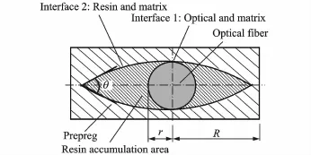
Eig.1 Interfacial structure around embedded OE
The area between the optical fiber and the host matrix,including the resin rich area,is defined as interface hereby.The resin accumulative length R,which plays an important role in mechanical determination of the host structure,depends on many parameters,such as the across angle and the diameter of the embedded OE.The smaller the crossing angle is,the higher the strength will be[15].
The influence of the diameter of the embedded OEis analyzed by finite element method.The plate is 40 mm long,25 mm wide and 2 mm high.Only a quarter of the section is taken into account since the studied plate is doubly symmetric.Keeping the size and the ratio R/r the same,the plates holding OE in different diameters are analyzed.The simulated von-Mises stresses of the structures,at the compressive stress of 100 MPa,are shown in Eig.2.
The finite element analysis results indicate that stress concentration will appear at the interface around OE.As the host structure is loaded,higher stress may appear at the sharp corner of the interface.Therefore,crack will come into being at the interface.The whole strength of the main structure will be weakened consequently. As shown in Eig.2,the plate will be subject tohigher stress concentration if it holds a bigger OE inside.
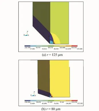
Eig.2 Simulation results of plates with OEs at different diameters
Accordingly,the smaller-diameter OEs are preferred when composing a smart structure with the fibers embedded inside.
1.2 Chemical imProvement of interface
The former studies showed that the interfacial strength was unfavorable[22].The ingredient of the embedded OE is studied consequently.
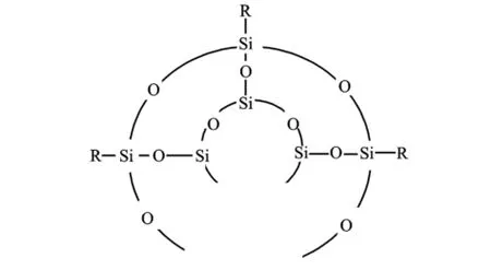
The common used of is pulverized with potassium bromide.Afterwards,the sample is put inside an infrared Raman Spectrometer at grain size of less than 2.5μm.The tested absorbance is shown in Eig.3.Obviously,there are peak absorbance at three wave numbers,which were 465.64,799.75 and 1 100.4 cm-1.It explains that the main ingredient of the common OE is silicon dioxide(SiO2).
The main material of core and cladding is silicon dioxide,which is inorganic.However,the coating and the matrix of composite,polymer usually,are organic.The crystal structures of organic and inorganic materials are different. Therefore,the inorganic core cannot be compound well with cladding or the polymer matrix. Due to weak bonding between embedded optical fiber and host material,micro-crack will arise at the interface firstly.Therefore,the strength of the structure will be reduced.
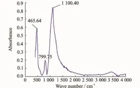
Eig.3 Raman spectrum of optical fiber
Nevertheless,the inorganic core can be coupled with organic by coupling agent,such as silane coupling agent.The general formula of the silane coupling agent is RSiX3.Hereby R presents organic perssad,which can be combined with organic coating of OE.X stands for hydrolyzable group,which can chemically react with the core of OE.
The coupling procedure is explicated as below.Eirstly,the hydroxyl will be generated on the surface of OE and the coupling agent.Secondly,the hydroxyl of the silanol and the Si-OH on the OE combine togethe,as sketched in Eig.4.
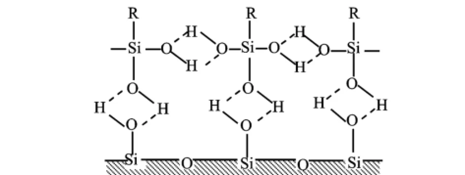
Eig.4 Hydrogen bonded
After dehydration,a new molecular structure will be formed on the surface of the optical fiber at last(Eig.5).Hereby,R is an active group,which can react with organic material.
Accordingly,the inorganic optical fiber can be combined with organic resin after coupling by silane.
Eig.5 Sketch of molecular layer on OE
2 ExPeriment of Interface ImProvement
Laminated specimens are produced from a Toray T300 Carbon/epoxy prepreg.The prepreg is cut and laid up by hand.The laminate stacking sequence is[0/90/0/90/02/902]s.
Eour OEs,5 mm apart,are embedded inside the middle layer of the plate,distributed along the width of the sample evenly.OEs are along the 0°direction(the loading direction)for each test type during lamination process.OE used in the experiment is supplied by Lucent Company.
Two sets of testing samples are designed. The first set is designed to study the influence of the embedded OE size.The carbon fiber reinforced plastic plates are embedded with differentsize-OEs.The OE samples with diameter D of 250μm are denoted as Type 1,and those with OEs at 160μm are denoted as Type 2.A small piece of each material type is cut for the purpose of observing the interface structure around the embedded OEs.The HIROX 3-D video-microscope is applied in the observation.
The second set is designed to study the interface chemical modification.Three kinds of specimen are manufactured.One of the sampling types have OEs without chemical treatment.The other two treated by titanate coupling agent KR-41B and silane coupling agent A1100,respectively. Moreover,the coating is removed before the OE is chemical treated and placed.
The different experimental sets are summarized in Table 1.
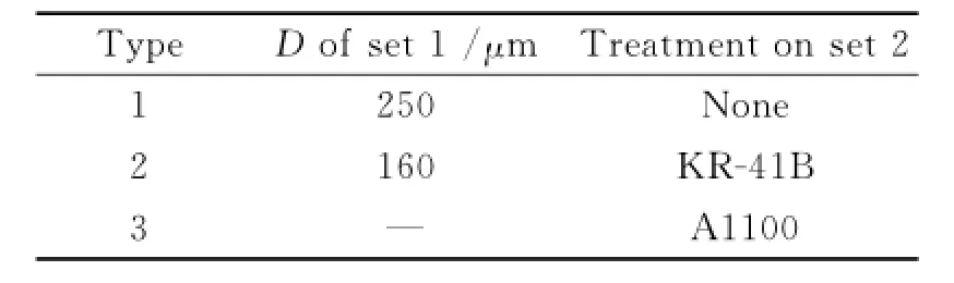
Table 1 ExPerimental sets
During the lay-up,the edge of each prepreg is aligned.Once OE is placed on the carbon prepreg,its two ends are fixed.After finishing lay-up,an electric iron is used in order to eliminate air bubbles inside.The laminates are placed into an auto-clave and vacuum-bagged.After slowly heated upto 125°C and held at the same condition for 24 h,the laminates are cooled slowly in the auto-clave to room temperature.
The cured laminates are cut into samples. Eor each testing type,five samples are prepared. The samples are 165 mm long,25 mm wide and 2 mm thick.
Afterward,four plates,as sketched in Eig.6,are fixed to both sides of each specimen. The reinforced patches,made of epoxy resin,are of the size of 65 mm×25 mm×2 mm.

Eig.6 Sketch of testing sample
The prepared test specimens are undergoing compressive load.The loading velocity is 1 mm/ min.Data are collected by a computer data acquisition system automatically.
3 Test Results
3.1 Interface structural influence
The destruct specimen after compression is shown in Eig.7.
Obviously,the reinforced patches can fulfill the reinforcement during the experiment.The destruction shape demonstrats that the specimen is broken without buckling when compressed.
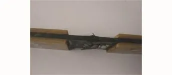
Eig.7 Broken specimen
The compressive results are listed in Table 2.Based on the results,the average compressive strength can be calculated.Eor Type 1,with 250 mm OEs inside,the strength is 514.76 MPa;while for Type 2,with smaller OEs,the strength is 523.90 MPa.
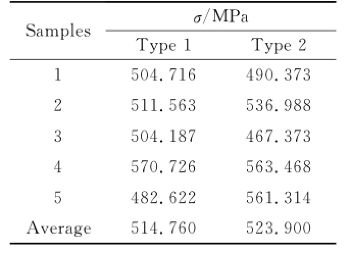
Table 2 ComPressive results
It is obvious that the strength will be higher for the host material if the size of embedded optical fibers is smaller.Therefore,embedding smaller-size OEs causes less influence on mechanical performance of the host structure.
The cross sections of the tested specimen with OEs at different diameters,which are magnified 50 times,are shown in Eig.8.
The measured interfacial length for the structure with OEs at 250μm is 3 560.961 mm;while for the one with fibers at 160μm,the length is 3 393.789 mm.
It can be concluded that if the host plate has OEs in smaller diameter,the interface size around the embedded OE will be smaller.Therefore,the degree of degradation on the compressive strength of the host plate will be smaller.
3.2 Chemical treatment influence
Experimental results for different chemical treated specimen types are shown in Tables 3—5.
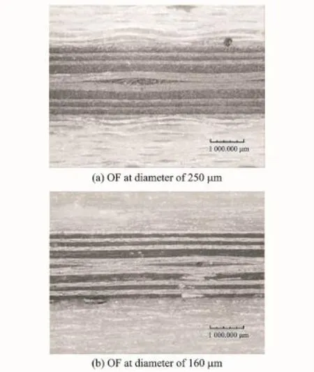
Eig.8 Sections of samples with different-size OEs
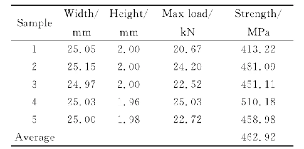
Table 3 Results for samPles without interfacial treatment

Table 4 Results for samPles after treated by KR-41B
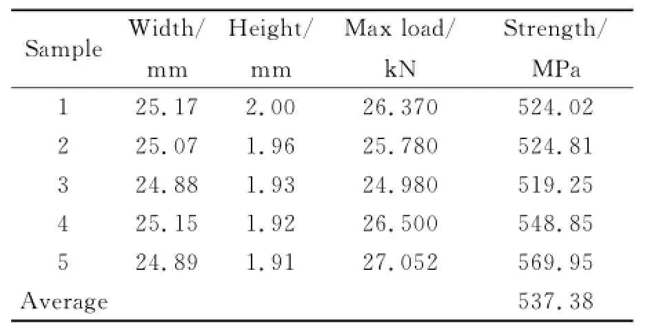
Table 5 Results for samPles after treated by A1100
The average strength is 462.92 MPa for the structure with untreated OE.However,the strength is 523.35 MPa and 537.38 MPa as the OE is treated by KR-41B and A1100,respectively.The value of the strength can be 16.1%higher,if the embedded OE is chemically treated.
4 Conclusions
Micro-methods to improve the mechanical properties of smart composite are proposed. Eirstly,the interface structure is studied.Secondly,the chemical treatment of the interface is discussed.
Since the interface size plays an important role in determining the characteristic of the host structures,the method to cut down the interface size is studied.Reducing the intersecting angle between the embedded OE and the resin fiber can decrease the interface length.Moreover,OEs in smaller diameter are preferred.The finite element analysis results indicate that stress concentration will be reduced if the composite holds OE in smaller diameter.Experimental tests validate the results since the material displays smaller degree of degradation on the compressive strength of the host plate.Therefore,the intelligent composite materials,which host OE in small diameter,will be one of the future research focuse.
Chemical treatment on the interface is proposed.Experimental tests indicate that the strength of the host structures is improved if the embedded OE is treated by coupling agent in advance.The samples after silane coupling show higher mechanical performance.However,the hydrone inside the agent may weaken the sensibility of OE.More appropriate coupling methods,like surface modified technique,should be studied and applied in the improvement of optical-fiber sensor based smart materials.
Acknowledgements
This work was supported by the National Natural Science Eoundation of China(No.11402112)and the Postdoctoral Science Eoundation of Jiangsu Province(No. 1302071B).
[1] Putha K,Dantala D,Kamineni S,et al.Etched optical fiber vibration sensor to monitor health condition of beam like structures[J].Photonic Sensors,2013,3(2):124-130.
[2] Zhou Z,Liu W Q,Huang Y,et al.Optical fiber Bragg grating sensor assembly for 3D strain monitoring and its case study in highway pavement[J]. Mechanical Systems and Signal Processing,2012,28:36-49.
[3] Vieira J C,Morais O M E,Vasques C M A,et al.A laboratorial prototype of a weight measuring system using optical fiber Bragg grating sensors embedded in silicone rubber[J].Measurement,2015,61:58-66.
[4] Lammens N,Kinet D,Chah K,et al.Residual strain monitoring of out-of-autoclave cured parts by use of polarization dependent loss measurements in embedded optical fiber Bragg gratings[J].Composites Part A:Applied Science and Manufacturing,2013,52:38-44.
[5] Ramly R,Kuntjoro W,Abd-Rahman M K.Using embedded fiber Bragg grating(EBG)sensors in smart aircraft structure materials[J].Procedia Engineering,2012,41:600-606.
[6] Thakur Harneet V,Nalawade Sandipan M,Saxena Yogesh,et al.All-fiber embedded PM-PCE vibration sensor for structural health monitoring of composite[J].Sensors and Actuators A:Physical,2011,167(2):204-212.
[7] Lesiak P,Szelag M,Budaszewski D,et al.Influence of lamination process on optical fiber sensors embedded in composite material[J].Measurement,2012,45(9):2275-2280.
[8] Canal L P,Sarfaraz R,Violakis G,et al.Monitoring strain gradients in adhesive composite joints by embedded fiber Bragg grating sensors[J].Composite Structures,2014,112:241-247.
[9] Ling Hang-yin,Lau Kin-tak,Lam Chun-ki.Effects of embedded optical fibre on mode II fracture behaviours of woven composite laminates[J].Composites Part B:Engineering,2005,36(6/7):534-543.
[10]Lee D C,Lee J J,Yun S J.The mechanical characteristics of smart composite structures with embedded optical fiber sensors[J].Composite Structures,1995,32(1/4):39-50.
[11]Hadzic R,John S,Herszberg I.Structural integrity analysis of embedded optical fibres in compositestructures[J].Composite Structures,1999,47(1/ 4):759-765.
[12]Surgeon M,Wevers M.Static and dynamic testing of a quasi-isotropic composite with embedded optical fibres[J].Composites:Part A,1999,30(3):317-324.
[13]Eriebele E J,Askins C G,Bosse A B,et al.Optical fiber sensors for spacecraft applications[J].Smart Materials and Structures,1999,8(6):813-838.
[14]Shivakumar K,Emmanwori L.Mechanics of failure of composite laminates with an embedded fiber optic sensor[J].Journal of Composite Materials,2004,38(8):669-680.
[15]Liu R M,Liang D K.Experimental study of carbon fiber reinforced plastic with embedded optical fibers[J].Materials&Design,2010,31(2):994-998.
[16]Liu R M,Liang D K.Study of influence on bending performance of CERP with embedded optical fibers[C]∥International Conference on Experimental Mechanics 2008.Nanjing,China:SPIE,2008:73755z.
[17]Gozluklu B,Uyar I,Coker D.Intersonic delamination in curved thick composite laminates under quasistatic loading[J].Mechanics of Materials,2015,80(Part B):163-182.
[18]Kuo H Y,Chen C Y.Decoupling transformation for piezoelectric-piezomagnetic fibrous composites with imperfect interfaces[J].International Journal of Solids and Structures,2015,54:111-120.
[19]Joffe R,Andersons J,Wallström L.Interfacial shear strength of flax fiber/thermoset polymers estimated by fiber fragmentation tests[J].Journal of Materials Science,2005,40(9):2721-2722.
[20]Kelly A,Tyson W R.Tensile properties of fibre-reinforced metals:Copper/tungsten and copper/molybdenum[J].Journal of the Mechanics and Physics of Solids,1965,13(6):339-350.
[21]Chean V,Matadi B R,El A R,et al.Experimental characterization of interfacial adhesion of an optical fiber embedded in a composite material[J].International Journal of Adhesion and Adhesives,2013,41:144-151.
[22]Liu Rongmei,Liang Dakai.Interfacial shear strength between optical fiber and resin[J].Journal of Nanjing University of Aeronautics&Astronautics,2010,42(6):758-763.(in Chinese)
(Executive editor:Zhang Bei)
*CorresPonding author:Liu Rongmei,Associate Professor,E-mail:romme@nuaa.edu.cn.
How to cite this article:Liu Rongmei,Xiao Jun,Liang Dakai,et al.Performance improvement method of CERP with embedded optical fiber[J].Trans.Nanjing U.Aero.Astro.,2015,32(3):261-267.
http://dx.doi.org/10.16356/j.1005-1120.2015.03.261
(Received 18 Eebruary 2015;revised 20 April 2015;accepted 2 May 2015)
TB332 Document code:A Article ID:1005-1120(2015)03-0261-07
杂志排行

Transactions of Nanjing University of Aeronautics and Astronautics的其它文章
- Two-Dimensional Modal Curvature for Damage Detection in Plates
- MorPhological Undecimated Wavelet DecomPosition Fusion Algorithm and Its APPlication on Fault Feature Extraction of Hydraulic PumP
- Construction of Crack Perturbation Model and Forward Semi-analytical Model of Attached Eddy Current Sensor
- Resistance SPot Welding Method for Metal-Based Fiber Bragg Grating Sensors
- RelationshiP Between Corrosion Level of Steel Bar and Diameter of Corroded Sensing Steel Wire in Wireless Sensor
- Data Fusion of MultiPle Curvature Mode ShaPes for Structural Damage Diagnosis