A numerical investigation of the flow between rotating conical cylinders of two different configurations*
2014-06-01LIXue李雪ZHANGJingjing张晶晶XULanxi许兰喜
LI Xue (李雪), ZHANG Jing-jing (张晶晶), XU Lan-xi (许兰喜)
Department of Mathematics, Beijing University of Chemical Technology, Beijing 100029, China,
E-mail: janemath@126.com
A numerical investigation of the flow between rotating conical cylinders of two different configurations*
LI Xue (李雪), ZHANG Jing-jing (张晶晶), XU Lan-xi (许兰喜)
Department of Mathematics, Beijing University of Chemical Technology, Beijing 100029, China,
E-mail: janemath@126.com
(Received December 11, 2012, Revised March 3, 2014)
The flow between two coaxial conical cylinders is numerically studied for two different configurations, with the inner cone rotating and the outer one at rest. It is found that, in one configuration,at least at a small Reynolds number (Re), the pressure is a decreasing function ofzwhile in the other configuration, it is an increasing function ofz. In the first configuration, the pressure curves for differentRehave intersections, while in the second configuration they do not. The gap between two conical cylinders is filled with six pairs of Taylor vortices at about the same Reynolds number and in each pair of vortices in the first configuration, the upper vortex is larger than the bottom one while in the second configuration, the bottom vortex is larger than the upper one.
rotating conical cylinder, Taylor vortex, Reynolds number, pressure distribution
Introduction
The flow between two concentric cylinders commonly referred to as the Taylor Couette flow is one of the most studied problem in fluid mechanics. It is a classical system used to investigate properties of flow driven by rotation. The results were numerous (see Refs.[1-7] and the references therein). The major interests were focussed on the occurrence of toroidal cells known as Taylor vortices.
The Taylor vortices may also occur in geometries other than between right circular cylinders, e.g., between rotating conical cylinders. In the last two decades, the Taylor vortices in the flow between two coaxial conical cylinders with inner cone rotating and outer one at rest were studied both experimentally and numerically. Wimmer[8]experimentally investigated the occurrence of the Taylor vortices and the influence of the governing parameters on the Taylor vortices. He showed that the laminar basic flow is three-dimen-sional. In Ref.[9], the transition to the turbulence was considered for the flow in a concentric annulus formed by conical cylinders of the same apex angle. The stability of the helical flow in the configuration of Fig.1(b) was experimentally investigated in Ref.[10], and it was found that the helical flow was resulted from a Hopf bifurcation. Noui-Mehidi et al.[11]studied the effect of the cylinder’s wall alignment on the flow. He also considered the bifurcations of the steady vortical structures in the case when the cylindrical walls are not perfectly parallel. Xu et al.[12]showed that the behavior of the flow is dominated by a competition between the meridional flow and the radial flow. It was found that the vortices occur in the direction toward smaller radius. The local minimum values of the velocity and the local maximum values of the pressure are attained at the same point whereas the velocity of the flow takes the local maximum at the point of the inflection for the pressure. Altmeyer et al.[13]studied the effects of the end wall on the transition between the Taylor vortices and the spiral vortices. Zhang et al.[14]analyzed the effects of the end plates on the flow in the configuration of Fig.1(b) and noted that the Taylor vortices filled the gap are in an odd number when the inner cone rotates together with the top end plate, whereas they are always in an even number inour case. However, all previous studies were mainly related to the configuration of Fig.1(b). At the same time, the flows in the configuration of Fig.1(a) were not given a due attention.

Fig.1 The sketch of two different configurations of coaxial rotating conical cylinders
Recently, the configuration of Fig.1(a) has caught our interest. A few chemists used the configuretion of Fig.1(a) as a precipitation reactor called the rotating liquid film reactor (RLFR), as the reactor to prepare new functional nano-particles. The gap between two cones is filled with reactants, which are usually considered as a viscous incompressible fluid. It is found that the particles produced in the RLFR are smaller in size and more concentrated in the size distribution, compared with the conventional precipitation reactors[15]. In order to understand the effect of the RLFR on the precipitation, it is necessary to investigate the flow properties in the gap. In order to do that, the configuration of Fig.1(a) should be considered and the flow property should be compared with that in Fig.1(b), which has motivated the study of this paper.
1. Mathematical formulation
The two different configurations are shown in Fig.1, in which the configuration in Fig.1(b) is just that in Fig.1(a) but upside down. The gap between two cones is filled with a viscous incompressible fluid. The inner cone rotates at the angular velocityΩand the outer one is at rest. For both configurations, we assume that the top and bottom end plates are rigid and the cone’s wall is a no-slip boundary. Then the governing equations (the Navier-Stokes equations) and the boundary conditions are as follows:

whereu,ρ,pandνare the velocity, the density, the pressure and the kinematic viscosity of the fluid, respectively. ∑top, ∑bottom, ∑innerand ∑outerrepresentR1(R2) andαare the hight of device, the radius of the inner (outer) cone at the thickest end and the cone’s inclination, respectively.
Parameter definitions: All our numerical results are described in term of following non-dimensional parameters.
Reynolds number:Re=dR1Ω/ν, aspect ratio the top end plate, the bottom end plate, the inner and outer cone’s walls, respectively,ωis the angular velocity of the cones. We adopt a Cartesian coordinate systemOxyzwithz-axis along the axis of rotation and the gravity in the negativez-direction.H,Γ=H/d, radius ratioη=R1/R2and cone’s inclination angleα.
2. Outline of the numerical method
2.1Outlines
The nonlinear and time dependent Eqs.(1) together with the boundary conditions (2) and the initial conditionsu|t=0=p|t=0=0 are integrated numerically using the finite volumes method. For the convection terms in the equations, a second-order upwind scheme is used to calculate the face values of the various quantities by interpolation from the cell centre values. The central difference quotient is used for the diffusion terms which are always accurate to the second order. The temporal discretization involves integrations of all terms in the differential equations with a time step Δt. The integration of the transient terms is implicit by using a second-order formulation. The SIMPLE algorithm is used to link the pressure and the velocity. The discretized equations are then solved sequentially using a segregated solver. The convergence is achieved when the residual falls below 10-4for the pressure and the three velocity components.
2.2Convergence and validation
The grids used for the numerical simulations consist of tetrahedral elements. Extensive grid-refining tests are conducted by varying the element order andthe time step. In order to improve the accuracy and the convergence rate, a hybrid correction technique is used, where four grid levels are adopted to refine sequentially in spatial dimensions. The solution obtained by a coarser grid is interpolated to initialize the solution on a finer grid. Figure 2 shows the convergence of the simulated results by comparing the profiles (normalized by the maximum value in the profiles) of the pressure and the velocity from four grids atRe= 192.5. The profiles with different resolutions essentially merge into one curve, suggesting the independence of the grids on the results. It is worth mentioning that the fourth grid level refinement (Case 4) leads to insignificant changes in the obtained solution, which means the convergence of the present simulated results.

Fig.2 Convergence studies of the profiles atΓ=12.5,η= 0.8,α=82oandRe=192.5 for the configuration of Fig.1(a). The number of grid points in Cases 1-4 are 224 932, 395 605, 532 698 and 736 806, respectively. The pressure and the velocity are normalized by the maximum value in the profiles.z/dmeans the value ofzin the axial direction is normalized by the width of the gap
3. Results and discussions
Numerical simulations of the flows in configuretions of Fig.1(a) and Fig.1(b) are carried out. Figure 3 displays the pressure distribution along the middle line atRe=12.5, 20, 25, 75 and 192.5, where the curves forRe=12.5, 20 and 25 are straight lines, corresponding to the laminar basic flow. The pressure curve fluctuates firstly at aboutRe=75, representing that the basic flow becomes unstable and the first Taylor vortex appears. The curve forRe=192.5 is full of fluctuations, representing that the gap is filled with six pairs of Taylor vortices (see Fig.4). For the configuration of Fig.1(a), it is shown that the pressure curves atRe=12.5, 20 and 25 decline with the increase ofzand the curves intersect while for the configuration of Fig.1(b) the pressure curves rise with the increase ofzand the curves do not intersect. After the basic flow becomes unstable, the declining trends of the pressure for the configuration of Fig.1(a) and the growth trends for the configuration of Fig.1(b) inz-direction remain, but no longer monotonically.

Fig.3 Pressure distributions along the middle line whenΓ= 12.5,η=0.8,α=82o
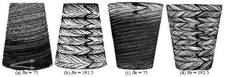
Fig.4 Streamlines of the flows whenΓ=12.5,η=0.8,α=82o. (a) and (c) represent the appearance of the first Taylor vortex, (b) and (d) show that the gap is filled with Taylor vortices

Fig.5 Sketch of occurrence and size of Taylor vortices in the configuration of Fig.1(a)
The phenomena in Fig.3 can be explained as follows: The laminar basic flow is driven by the imbalance of centrifugal forces in the gap. On the inner cone the circumferential velocity depends on thez-coordinate while on the outer cone it is always zero. Therefore, for the configuration of Fig.1(a), the circumferential velocity of the fluid in the gap decreases with the increase of radial and axial coordinates. This leads to a negative change rate of the centrifugal forces in bothr-direction andz-direction. Despite the negative change rate of the centrifugal forces in ther-direction, the change rate of the pressure inr-direction is always positive, because the fluid in the gap is thrown to the outside. Hence, for the configuration of Fig.1(a) the pressure along the middle line is a decreasing function ofz, at least for small Reynolds numbers. For large Reynolds numbers, the falling trend of the pressure remains, but no longer monotonic. However, for the configuration of Fig.1(b), a negative change rate of the centrifugal forces in ther-direction and a positive change rate of the centrifugal forces inz-direction are found, and as the results, the pressure along the middle line is an increasing function ofz, at least for smallRe. For large Reynolds numbers the growth trend of the pressure remains, but no longer monotonic. Upon increasing the Reynolds numbers, the centrifugal forces progressively dominate the viscous forces. Therefore, with increasing thez-coordinate, the centrifugal forces for the configuration of Fig.1(a) decrease more and more rapidly. As the result, the pressure inz-direction for a larger Reynolds number falls more rapidly than for a smaller Reynolds number, and the intersection of pressure curves occurs, as demonstrated in Fig.3(a). Similarly, for the configuration of Fig.1(b), the growth rate of the centrifugal forces inz-direction for a larger Reynolds number is greater than that for a smaller Reynolds number. As a result, for a larger Reynolds number the pressure increases more rapidly than for a smaller Reynolds number. Therefore, the pressure curves in Fig.3(b) have no intersection. The centrifugal force attains its maximum at the bottom. Therefore, the fluid at the bottom of the configuration of Fig.1(a) is deflected outwards and moves up in a spiral to the top in the vicinity of the outer cone then returns to the bottom near the inner cone, also in a spiral form, as shown in Fig.5(a). The basic flow is a large loop between the cone's surfaces. Our numerical calculations also show that the first Taylor vortex appears at the bottom of the configuration of Fig.1(a) and at the top of the configuration of Fig.1(b), at about the same Reynolds numberRe= 75. With a further increase of the Reynolds number another pair of vortices is generated, in the direction towards the smaller radius. At aboutRe=192.5 the gap is finally filled with six pairs of vortices, as displayed in Fig.4. If the vortex rotates in the direction of the basic flow it is stretched. If it rotates in the opposite direction it is compressed. As a consequence, in each pair of vortices, the top vortex is larger than the bottom one, as shown in Fig.5. However, for the configuration of Fig.1(b), in each pair of vortices, the top vortex is smaller than the bottom one, as is confirmed by Wimmer's experiment. For the configuration of Fig.1(a), there is no experiment result in this regard.
4. Conclusion
This work studies the flows in two different configurations of Fig.1(a) and Fig.1(b), focussing on the pressure distribution and the instability of the basic flow as well as the transition to Taylor vortices. A comparison of the pressure distribution and the behavior of the Taylor vortices is made. The results are summarized as follows: For the configuration of Fig.1(a) and at smallRethe pressure is a decreasing function ofz, for largeRethe declining trend inz-direction remains, but no longer monotonic. For the configuration of Fig.1(b), the pressure is an increasing function ofzat smallRe, for largeRethe growth trend inz-direction remains, but no longer monotonic. For the configuration of Fig.1(a), the pressure curves at differentRehave intersections while for the configuration of Fig.1(b) they do not. This shows that the declining rate of the pressure for the configuration of Fig.1(a) and the growth rate of the pressure for the configuration of Fig.1(b) is higher for a largerRethan for a smallerRe. At aboutRe=192.5 the gap of both configurations of Fig.1(a) and Fig.1(b) is filled with six pairs of Taylor vortices and in each pair of vortices in the configuration of Fig.1(a), the upper vortex is larger than the bottom one while in the configuration of Fig.1(b), the bottom vortex is larger than the upper one.
[1] DONG S. Direct numerical simulation of turbulent Taylor-Couette flow[J].Journal of Fluid Mechanics,2007, 587: 373-393.
[2] DONG S. Turbulent flow between counter-rotating concentric cylinders: a direct numerical simulation study[J].Journal of Fluid Mechanics,2008, 615: 371-399.
[3] DUBRULLE B., DAUCHOT O. and DAVIAUD F. et al. Stability and turbulent transport in Taylor-Couette flow from analysis of experimental data[J].Physics of Fluids,2005, 17(9): 095103.
[4] BURIN M. J., SCHARTMAN E. and JI H. Local measurements of turbulent angular momentum transport in circular Couette flow[J].Experiments in Fluids,2010, 48(5): 763-769.
[5] BILSON M., BREMHORST K. Direct numerical simulation of turbulent Taylor-Couette flow[J].Journal of Fluid Mechanics,2007, 579: 227-270.
[6] WANG Jia-song. Flow around a circular cylinder using a finite-volume TVD scheme based on a vector transformation approch[J].Journal of Hydrodynamics,2010, 22(2): 221-228.
[7] RAPLEY S., EASTWICK C. and SIMMONS K. Computational investigation of torque on coaxial rotating cones[J].Journal of Fluids Engineering,2008, 130(6): 061102.
[8] WIMMER M. Taylor vortices at different geometries[J].Physics of Rotating Fluids,2000, 549: 194-212.
[9] NOUI-MEHIDI M. N. Transition in the flow between conical cylinders[J].Experiments in Fluids,2001, 30(1): 84-87.
[10] NOUI-MEHIDI M. N., OHMURA N. and KATAOKA K. Dynamics of the helical flow between rotating conical cylinders[J].Journal of Fluids and Structures,2005, 20(3): 331-344.
[11] NOUI-MEHIDI M. N., OHMURA N. and NISHIYAMAET K. et al. Effect of wall alignment in a very short rotating annulus[J].Communications in Nonlinear Science and Numerical Simulation, 2009, 14(2): 613-621.
[12] XU X., WEN P. and XU L. et al. Occurrence of Taylor vortices in the flow between two rotating conical cylinders[J].Communications in Nonlinear Science and Numerical Simulation, 2010, 15(5): 1228-1239.
[13] ALTMEYER S., HOFFMANN C. H. and HEISE M. et al. End wall effects on the transitions between Taylor vortices and spiral vortices[J].Physical Review E,2010, 81(6): 066313.
[14] ZHANG Y., XU L. and LI D. Numerical computation of end plate effect on Taylor vortices between rotating conical cylinders[J].Communications in Nonlinear Science and Numerical Simulation, 2012, 17(1): 235-241.
[15] GUO S., EVANS D. G. and LI D. et al. Experimental and numerical investigation of the precipitation of barium salfate in a rotating liquid film reactor[J].AIChE Journal,2009, 55(8): 2024-2034.
10.1016/S1001-6058(14)60049-4
* Biography: LI Xue (1979-), Female, Ph. D. Candidate
XU Lan-xi,
E-mail: xulx@mail.buct.edu.cn
猜你喜欢
杂志排行

水动力学研究与进展 B辑的其它文章
- Numerical simulation of landslide-generated impulse wave*
- A random walk simulation of scalar mixing in flows through submerged vegetations*
- Scaling of maximum probability density function of velocity increments in turbulent Rayleigh-Bénard convection*
- Dispersion in oscillatory electro-osmotic flow through a parallel-plate channel with kinetic sorptive exchange at walls*
- Evaluation of the use of surrogateLaminaria digitatain eco-hydraulic laboratory experiments*
- A numerical study on dispersion of particles from the surface of a circular cylinder placed in a gas flow using discrete vortex method*