A novel functional electrical stimulation-control system for restoring motor function of post-stroke hemiplegic patients
2014-06-01ZonghaoHuangZhigongWangXiaoyingLvYuxuanZhouHaipengWangSihaoZong
Zonghao Huang, Zhigong Wang,, Xiaoying Lv, Yuxuan Zhou Haipeng Wang, Sihao Zong
1 Institute of RF- & OE-ICs, Southeast University, Nanjing, Jiangsu Province, China
2 State Key Lab of Bioelectronics, Southeast University, Nanjing, Jiangsu Province, China
3 Co-innovation Center of Neuroregeneration, Nantong University, Nantong, Jiangsu Province, China
A novel functional electrical stimulation-control system for restoring motor function of post-stroke hemiplegic patients
Zonghao Huang1, Zhigong Wang1,3, Xiaoying Lv2,3, Yuxuan Zhou2, Haipeng Wang1, Sihao Zong1
1 Institute of RF- & OE-ICs, Southeast University, Nanjing, Jiangsu Province, China
2 State Key Lab of Bioelectronics, Southeast University, Nanjing, Jiangsu Province, China
3 Co-innovation Center of Neuroregeneration, Nantong University, Nantong, Jiangsu Province, China
Hemiparesis is one of the most common consequences of stroke. Advanced rehabilitation techniques are essential for restoring motor function in hemiplegic patients. Functional electrical stimulation applied to the affected limb based on myoelectric signal from the unaffected limb is a promising therapy for hemiplegia. In this study, we developed a prototype system for evaluating this novel functional electrical stimulation-control strategy. Based on surface electromyography and a vector machine model, a self-administered, multi-movement, force-modulation functional electrical stimulation-prototype system for hemiplegia was implemented. This paper discusses the hardware design, the algorithm of the system, and key points of the self-oscillation-prone system. The experimental results demonstrate the feasibility of the prototype system for further clinical trials, which is being conducted to evaluate the ef fi cacy of the proposed rehabilitation technique.
nerve regeneration; stroke; motor function; rehabilitation; functional electrical stimulation; surface electromyography; stimulator circuit; neural regeneration
Funding: This work was supported by the National Natural Science Foundation of China, No. 90307013, 90707005 and a grant from the Science & Technology Pillar Program of Jiangsu Province in China, No. BE2013706.
Huang ZH, Wang ZG, Lv XY, Zhou YX, Wang HP, Zong SH. A novel functional electrical stimulation-control system for restoring motor function of post-stroke hemiplegic patients. Neural Regen Res. 2014;9(23):2102-2110.
Introduction
Stroke is the second commonest cause of death and leading cause of adult disability worldwide (Bonita et al., 2004). It is also a serious public health problem in China. It was estimated that about 1.5—2 million new strokes occurred each year in China (Liu et al., 2007). Ischemic stroke is the most prevalent type of stroke (representing 62.4% of strokes in China and 87% of strokes in the USA), and hemiparesis is its most common consequence (Zhang et al., 2003; Go et al., 2013). Because the most common type of ischemic stroke occurs in the middle cerebral artery (Dobkin, 2004) and primarily affects the upper limbs, many stroke survivors lose upper-limb function, which substantially limits their ability to engage in basic activities of daily living. Moreover, there are only 14,000 registered rehabilitation therapists in all of China (Jones and Skinner, 2013), which translates into one therapist for every 62,400 Chinese people who suffer an ischemic stroke). This gap between the number of poststroke hemiplegia patients and therapists is extremely large. Therefore, it is imperative for China to develop effective, self-administered, home-use rehabilitation training systems that focus on the upper limbs for these patients.
Several advanced rehabilitation techniques have been developed. Studies suggest that active, repetitive, task-speci fi c movement of the impaired limb is important for facilitating motor recovery after stroke (Taub et al., 1993, 1999). Continued therapy with advanced rehabilitation techniques, such as constraint-induced movement therapy (Taub et al., 1999; Grotta et al., 2004), robot-assisted movement (Lum et al., 2002; Kwakkel et al., 2007), electromyography-triggered neuromuscular electrical stimulation of paretic muscles (Cauraugh et al., 2000), motor imagery techniques (Dickstein and Deutsch, 2007), and bilateral symmetric exercise (Cauraugh and Summers, 2005; Lin et al., 2010) may improve motor function in the paretic limbs of stroke survivors for more than 6 months after stroke. However, many emerging therapies require residual movement of the impaired limb, which limits their application. Moreover, some of these techniques require long intensive therapy sessions or expensive equipment, which make them dif fi cult to implement in the current health care environment (Knutson et al., 2007). Therefore, these principles and techniques may be inappropriate for self-administered, home-use, rehabilitation training systems.
Contralaterally controlled functional electrical stimulation (CCFES) (Knutson et al., 2007, 2012) is another prom-ising therapy for hemiplegia rehabilitation after stroke. This method uses signals from bend sensors placed on the non-paretic side of the body to regulate the intensity of electrical stimulation delivered to the paretic muscles of the homologous limb on the opposite side of the body. The advantages of this therapy, such as being applicable to severely disabled stroke survivors and not requiring long intensive therapy sessions or equipment, have been previously discussed (Knutson et al., 2007). However, in the original system, the intensity of electrical stimulation only depends on the angle of the limb, which is detected by the bend sensor, and not on the force exerted by the unaffected limb. Moreover, in these FES systems (Knutson et al., 2007; 2012), hemiplegic patients can only practice one training movement at a time. In contrast, the stimulation intensity in our new system proposed here is modulated by force and the system is designed for multi-movement rehabilitation training.
Methods
Modulation of stimulation intensity
We used surface electromyography (SEMG) as an indicator of limb force. Here, we propose a stimulation-generating algorithm. Brie fl y, a threshold for the magnitude of the SEMG and a maximum frequency are set within the algorithm. When the amplitude of the SEMG exceeds the threshold, one electrical pulse for stimulation is triggered. The maximum frequency determines the maximum intensity of the generated pulse sequence. To maximize the performance of the algorithm, the threshold and maximum frequency need to be chosen carefully.
Six male healthy subjects (aged 25—30 years) were recruited randomly for testing the stimulation-generating algorithm, and informed consent was obtained from each subject. Note that none of the subjects in this part of the study were stroke patients. Each subject participated in four sessions. During each session, subjects were comfortably seated and instructed to keep their wrists in a certain position as 0, 1, 2, or 3 kg weights were applied to them (Figure 1A). The weight in the fi rst session was 0 kg, and this was increased by 1 kg in each subsequent session. Subjects rested for 3 minutes between each session to prevent muscle fatigue. During each session, subjects were instructed to maintain their wrist positions for 5 seconds, and the SEMG signal of the extensor carpi radialis longus muscle was recorded using a Bagnoli-16 EMG system (Delsys Inc., Natick, MA, USA) with 10-kHz sampling rate (Figure 1B). To obtain a stable signal, SEMG signals in a 3-to 4-second time window were used for analysis. Because maintaining wrist position with different weights can be considered an isometric contraction of the extensor carpi radialis longus muscle, the weight may be considered as an index of the muscle contraction. Therefore, the weight has been normalized to maximal voluntary contraction (MVC). The generated stimulation frequency (SF) (pulse number per second) at different MVCs can be seen inFigure 1C(black squares). Note that the SEMG threshold for each subject was different.
The relationship between the MVC and the stimulation frequency generated by the stimulation-generating algorithm can also be seen inFigure 1C. Linear and square fi ts were used to illustrate the relationship between the MVC and stimulation frequency, and the fi tting result is presented inTable 1. The R-square value indicates the goodness of fi t of the model, with higher R-square values indicating a better fi t to the data (Draper and Smith, 1998). We also calculated the statistic linearity de fi ned by equation (1), which indicates the residuals from the linear model. In equation (1), ΔSFmaxis the maximal deviation between the data and the fi tted line; SFmaxand SFminare the maximal and minimal stimulation intensities, respectively.
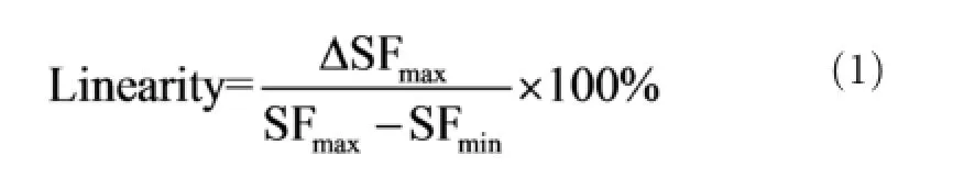
Figure 1andTable 1clearly show that SF increased with MVC, indicating that stimulation frequency can be modulated by the force exerted by detected muscle. Note that, for some subjects, the SF was not zero even when the weight was zero because of the weight of the subject’s hand. The stimulation-generating algorithm can be implemented by a micro-controller unit (MCU) in real-time at a very low computing cost. The hardware implementation is based on the timer interrupt service request (ISR) of the MCU, and the implementation fl owchart can be seen inFigure 2.
The stimulation-generating algorithm is executed every 500 μs when the timer interrupt of the MCU occurs. The digital to analog converter (DAC) updates the output according to the execution result of the algorithm. The worst execution time of this algorithm was measured as 29.4 μs using an 8-MHz MCU clock with a 2-kHz sampling rate (only 5.88% of the maximal computing capability of the MCU). Therefore, based on this fi nding and those presented inFigure 1andTable 1, we concluded that at a very low computing cost, the proposed stimulation-generating algorithm can be used to modulate the intensity of the electrical stimulation according to the force exerted by the muscle.
Classi fi er for multi-movements
To implement multi-movement FES training, the single-channel stimulation-generating algorithm proposed above was improved using a support vector machine (SVM). The SVM is a supervised learning model with an associated learning algorithm that is used for classification and regression analysis (Cristianini and Shawe-Taylor, 2000). The primary improvement in the algorithm was an increased number of SEMG recording channels, using the proposed stimulation-generating algorithm for each channel and the SVM to determine which channel should generate the output stimulation. We chose wrist extension and fl exion to test the performance of the improved algorithm. The same subjects who tested the stimulation-generating algorithm (see “Modulation of stimulation intensity”) were recruited for the SVM training, and informed consent was again obtained from each subject. Ag/AgCl ECG electrodes witha diameter of 10 mm were used as SEMG recording electrodes because of their low half-cell potential (approximately 220 mV), their accessibility, their ability to reject motion artifacts, and their response to de fi brillation currents (Lee and Kruse, 2008). Three electrodes were placed on the fl exor carpi radialis muscle (agonistic muscles for wrist fl exion) and the extensor carpi radialis longus muscle (agonistic muscles for wrist extension), for a total of six electrodes on the left arm (Figure 3A). The SEMG signal was recorded using the prototype system ( fl exor muscle: channel 1 [CH1]; extensor muscle, CH2). Signals detected from subjects 1—5 were used for training the SVM, and those from subject 6 were used for testing the prototype system.
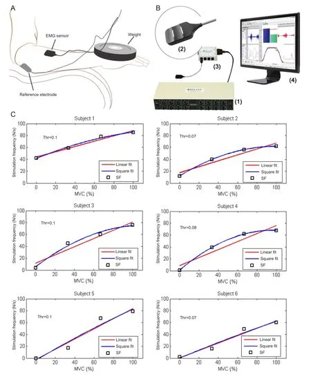
Figure 1 Schematic representation of the experiment (A), signal acquisition software (B), and relationship between maximal voluntary contraction (MVC) and the generated stimulation frequency (SF) in six participants (C).
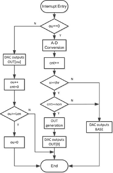
Figure 2 Hardware implementation fl owchart of the stimulationgenerating algorithm.
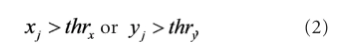
A scatter plot of CH1 analog to digital (AD) values versus CH2 AD values is shown in Figure 3B (CH1, red; CH2, blue; n = 5). For each data point (xj, yj), xjand yjare the AD values at moment j of CH1 and CH2, respectively. The data (xj, yj) are denoted as Dj. The thresholds for CH1 and CH2 are denoted as thrxand thry. If Djdid not satisfy
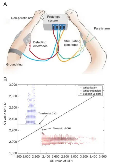
Figure 3 Schematic representation of the surface electromyography recording procedure (A) and a scatter plot showing the analog to digital (AD) values for each channel (n= 5) (B).
it was discarded. The remaining Djvalues were fed into the classi fi er, de fi ned as
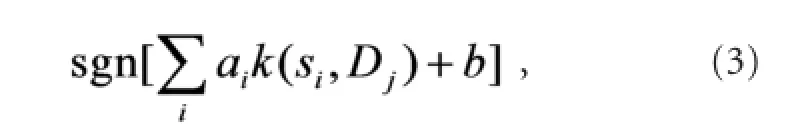
where siare the support vectors, aiare the weights, b is the bias, and k(•) is a kernel function. In this case, we chose a linear kernel.
When equation (3) equaled 1, (xj, yj) was classified as‘wrist extension’, and when equation (3) equaled −1, it was classi fi ed as ‘wrist fl exion’. Considering the complexity of the hardware implementation, from equation (3), we derive the boundary equation of the two classes:
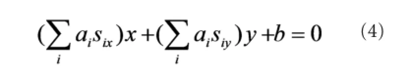
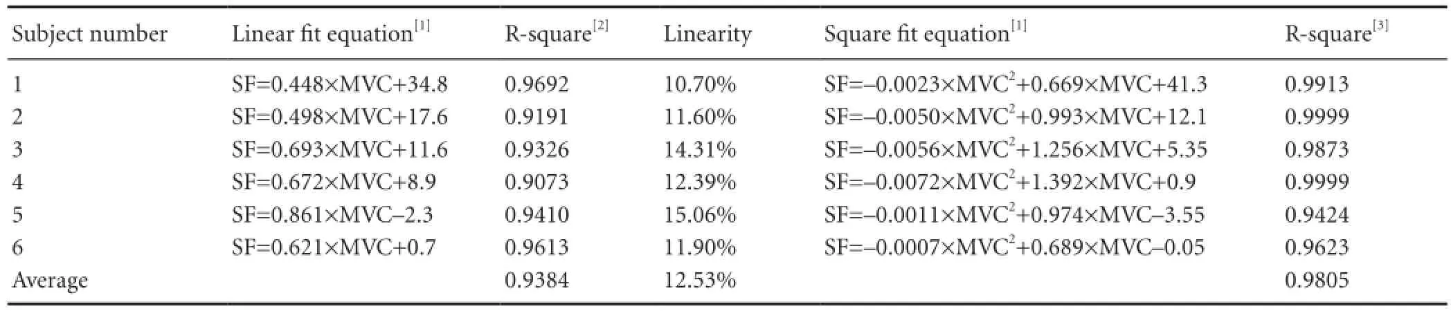
Table 1 Fitting result and linearity of the stimulation-generating algorithm
Where sixand siyare the respective x- and y-axis values of the support vector si. The values for six, siy, aiand b can be calculated with the SVM toolbox in Matlab (MathWorks Inc., Natick, MA, USA) based on the recorded experimental SEMG data. Substituting the calculated value into equation (4), we obtain the following boundary equation:

Equation (5) can be easily implemented by hardware at a very low computing cost. The number of recording channels can be increased to improve the classifier accuracy. In this situation, the boundary equation will become a more complicated hyperplane, and the computing cost will increase. The location of the electrodes is essential for the accuracy of the classi fi er, and we optimized the location for each subject. Because the agonistic muscles for wrist flexion and extension are separated in space, the classifier accuracy can be very high. For movements such as wrist extension and fi nger extension, a two-dimensional SVM may not yield accurate results because the extensor muscles of the wrist and fi ngers are in very close spatial proximity. We have developed a more efficient and complicated method for this situation, which will be published in the future.
System hardware
Figure 4shows a block diagram and photograph of the prototype system. The main components include two EMG detecting circuits (EDCs), one digital signal processor (DSP), two functional electrical stimulators, a power management circuit, and a user interface.
The differential SEMG signal from the desired muscles of the non-paretic limb is amplified and filtered by the EDC. The EDC also contains a body potential driver (BPD) circuit to eliminate interference. The output analog signals of the EDCs are converted to digital codes by the analog-to-digital converters (ADCs) contained in the DSP. Because the computing cost of the proposed algorithm is very low, we did not need to choose an expensive digital signal processor with high computing ability. An ultra-low power-consumption mixed-signal micro-controller MSP430F169 (Texas Instruments Inc., Dallas, TX, USA) was chosen as the digital signal processor. This micro-controller also integrates 8-channel 12-bit ADCs and 2-channel 12-bit digital-to-analog converters (DACs), which are used for arbitrary generation of stimulating waveforms. The pulses generated by the DACs are transmitted to the stimulators, where current signals suitable for neuromuscular stimulation are generated. The current amplitude of the stimulating signals can be adjusted through the control panel. Additionally, the “non-paretic to paretic limb” or “normal electrical stimulation” modes can be selected from the control panel. The entire prototype system is powered by a 12-V Li battery. The main functions of the power management circuit are to generate different voltages for the system and to indicate battery level.
The EMG-detecting circuit
Each EDC contained the following parts: a preamplifier, a high-pass filter, a low-pass filter, a two-stage amplifier, a DC-level control circuit, and a BPD circuit. Each part of the EDC is presented inFigure 5.
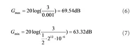
Amplitudes of the SEMG signals vary from several μV to several mV (Basmajian and De Luca, 1985). Considering the precision (12-bits) and the reference voltage (3 V) of the ADC, the maximum and the minimum gain of the EDC (indicated as Gmaxand Gminin equations 6 and 7) can be calculated as follows:
Therefore, we chose

in which, GEDCis the gain of the EDC.
We set the bandwidth range of the EDC to 200—1,000 Hz, considering the frequency characteristics of SEMG signals (Basmajian and De Luca, 1985; De Luca, 2002; De Luca et al., 2010) and potential sources of interference (De Luca, 2002; Huang et al., 2011; Pincivero, 2000), such as ambient noise, inherent noise in electronic components, inherent instability of SEMG, and motion artifacts. The AD sampling rate was set 2 kHz for each channel. Several measures were adopted to reduce noise and interference:
(1) Because most interference is derived from common mode signals, an instrument amplifier configured as a differential ampli fi er INA128 (Texas Instruments Inc.) with a high common mode reject ratio (CMRR) (about 120 dB at 100 Hz) was used in the preampli fi er. Considering the fact that many instrumental ampli fi ers have virtually no CMRR above 20 kHz (Kitchin and Counts, 2003), we included a fi ltering network for reducing errors in the radio frequency interference (RFI) recti fi cation in the front of the instrumental ampli fi er. A BPD circuit was also used with the instrument ampli fi er to reduce the common mode voltage. Parameters of the BPD were chosen carefully because inappropriate parameters may cause instability (Winter and Webster, 1983).
(2) To combat compromised signal fidelity and noise/ interference suppression, an 8th-order high-pass fi lter with a cutoff frequency of 200 Hz was used to suppress the 1st, 2nd, and 3rdharmonics of the AC power supply, noise/interference introduced by motion artifacts, and inherent instability of the SEMG signal. This high pass fi lter was made from a fourstage Sallen-Key high pass fi lter (Sallen and Key, 1955), and the parameters for each stage were optimized for filtering performance and stability. Because the single/multi-channel stimulation-generating algorithm is based on a threshold, its performance is susceptible to input signal drift. A high-pass filter with a proper cutoff frequency was thus essential for the system.
(3) High input impedance reduces interference (Metting van Rijn et al., 1990). Therefore, a field-effect transistor (FET)-input operational amplifier OPA132 (Texas Instruments Inc.) with an input impedance of 1013Ω||2pF was used as the buffer stage. A guarding technique was also used to improve the impedance of the system.
(4) The prototype system was powered by a Li battery, which provides safety and power frequency rejection. Shielding was used to reduce the capacitance between the AC power supply and the system and between the ground and the system.
Functional electrical stimulator design
A schematic representation of the two-channel, arbitrary-output, isolated high-compliance voltage stimulator is presented inFigure 6. The non-isolated sides of CH1 and CH2 share the power and ground with the DSP. The isolated side of each channel has a separate power and ground (denoted as GND1 and GND2). Additionally, GND1 and GND2 are isolated from each other. A precision low-cost isolation amplifier ISO124 (Texas Instruments Inc.) was used as A11 and A21. Filters made up of A12 and A22 were added to eliminate the output ripple without decreasing the 50-kHz signal bandwidth of the isolation amplifier. A13, A14, A23, and A24 comprise the voltage-current converters for stimulation, which are based on the advantage of a current-source-based stimulator (Merril et al., 2005). For obtaining high voltage output without decreasing the signal bandwidth, a high-voltage, high-current dual operational amplifier OPA2544 (Texas Instruments Inc.) was used for A13, A14, A23, and A34. The high voltages HVCC1, HVEE1, HVCC2, and HVEE2 were provided by two commercial DCDC modules. The maximum/minimum compliance voltage of a single channel was ± 34 V, and the maximum current was 2A. The outputs of the DACs for the DSP were used as the inputs to the stimulator, and were denoted as DAC1 and DAC2 for arbitrary waveform generation. Considering effective action potential initiation and tissue damage (Merril et al., 2005), a charge-balanced stimulating waveform was used for functional electrical stimulation.
Results
The prototype system was tested on subject 6 as illustrated inFigure 3A. The left and right arms of the participant were considered the non-paretic and paretic arms, respectively. CH1 detection electrodes were placed on the flexor carpi radialis muscle (agonistic muscle for wrist flexion) of the non-paretic arm, and CH2 detection electrodes were placed on the extensor carpi radialis longus muscle (agonistic muscle for wrist extension) of the non-paretic arm. CH1 and CH2 stimulating electrodes were placed on the agonistic muscles for wrist flexion and wrist extension, respectively. The placements of both the detecting and stimulating electrodes were determined experimentally and with the analysis of the agonistic muscles. The outputs of EDC CH1, EDC CH2, DAC1, and DAC2 (inputs of stimulator CH1 and CH2, separately) were recorded during alternating extension and fl exion of the non-paretic wrist (Figure 7).
As shown inFigure 7, the stimulating pulse sequence generated by either DAC1 or DAC2 depends on the movement of the wrist. When the unaffected wrist flexes, the stimulator, which is connected to the agonistic muscles for wrist flexion, stimulates the flexor muscle of the affected limb, causing it to contract. Thus, wrist flexion of the affected wrist can be achieved. The wrist extension of the affected wrist can be achieved in the same manner.Figure 7Bshows an enlargement of the inset highlighted as ‘part I’ inFigure 7A. The fi gure depicts an SEMG that exceeded the amplitude threshold and triggered a charge-balanced biphasic and slow reversal waveform with a 500-μs width stimulating pulse. The stimulating waveform was not triggered during the refractory period (about 8 ms). This period determined the maximal stimulating frequency of the prototype system. From the data depicted inFigure 7, we preliminarily conclude that we succeeded in implementing a self-administered, force-regulated, and multi-movement FES prototype system. The clinical trial based on this prototype system is in progress at Zhong-Da hospital, Southeast University, as shown inFigure 8. The results will be published in the future.
Discussion
The proposed FES prototype system is a promising training device for patients with hemiplegia after stroke. The proposed system has three advantages over existing systems that are widely used in China. (1) It incorporates several important rehabilitation principles, such as intention-driven movement (Nudo et al., 1996) and bilateral movement (Luftet al., 2004), and creating a strong perception of restored motor control (Knutson et al., 2012). (2) It is a self-administered FES system, which may reduce the therapist’s workload during rehabilitation. (3) The cost of the system is low and the system is small, which make it suitable for home use.
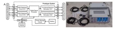
Figure 4 Block diagram (A) and photograph (B) of the prototype system with the detection and stimulation EMG electrodes.
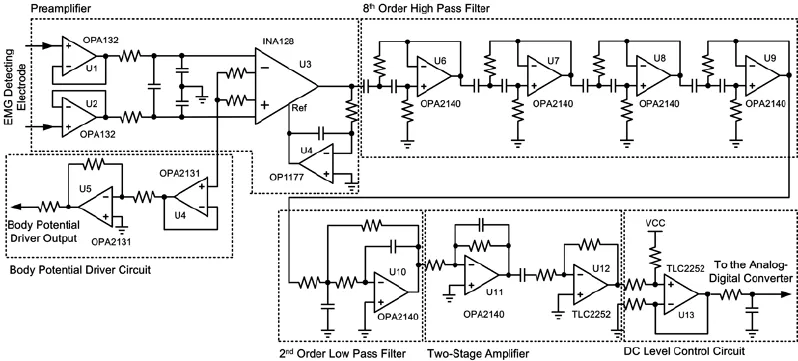
Figure 5 Schematic diagram of the electromyography (EMG) detecting circuit (EDC).

Figure 6 Schematic diagram of the 2-channel stimulator.
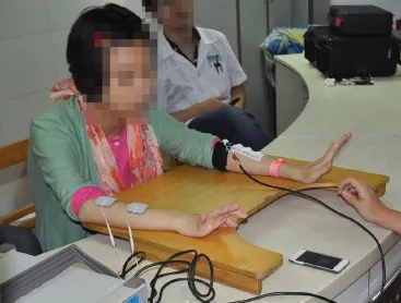
Figure 8 A patient with hemiplegia caused by stroke practicing with the proposed electrical stimulation-prototype system.
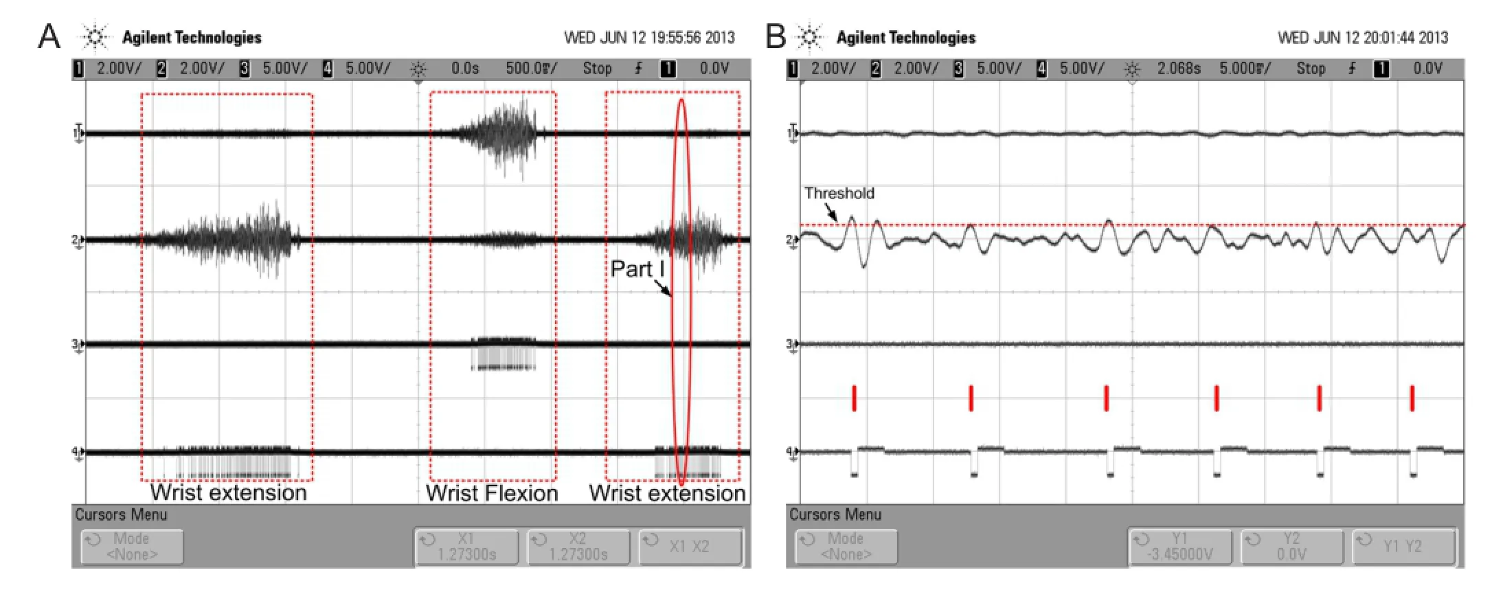
Figure 7 Experimental result of the prototype system recorded during alternating extension and fl exion of the non-paretic wrist.
During voluntary contractions, the central nervous system controls muscle force by modulating both the activation frequency and the number of motor units (Person and Kudina, 1972; Thomas and Del Valle, 2001). In contrast, most clinical FES systems use a constant frequency, and only modify the stimulation intensity (the number of recruited motor units) to control the muscle force (Lyons et al., 2000; Peckham and Knutson, 2005; Chou et al., 2008). However, it has been reported that modulating stimulating frequency was effective in maintaining muscle force production during repetitive electric stimulation (Kebaetse and Binder-Macleod, 2004; Kebaetse et al., 2005; Chou et al., 2008). Our proposed FES prototype implements stimulating-frequency modulation at a very low computational cost. The modulation algorithm for both stimulation intensity and frequency is also being studied in our research group.
Because the detection and stimulating electrodes are both placed on the body, the stimulating signals are coupled with the detecting electrode. Therefore, positive feedback can be easily established, which leads to self-oscillation. In the experiments, we found that the ground ring on the non-paretic limb (Figure 3A), which connects to the ground for the detecting electrodes (GND inFigure 6), effectively restricted self-oscillation. Moreover, we found that self-oscillation also depended on waveform parameters of the stimulating pulse, such as its width. For example, a wider pulse width was associated with a higher likelihood of self-oscillation. In future studies, the EDC should be improved to limit detection of stimulation artifacts via an artifact elimination circuit.
The use of a Li battery as the power supply solves many safety issues and eliminates certain aspects of safety tests, such as power line voltage dips, interruptions, and variations (IEC-61000-4-11), electrical fast transients (EFTs) (IEC-61000-4-4), and surges (IEC-610000-4-5). Additionally, use of a Li battery also improves interference suppression over that of AC-powered systems, which is important for weak signal detection. Our prototype system has been tested in many complex electromagnetic environments, and the battery-powered system performs well.
Although an arbitrary waveform, high-voltage, isolated electrical stimulator can be achieved based on a DAC and an integrated power-operational ampli fi er, the adoption of a power-operational amplifier results in large static power consumption, and the absolute maximum supply voltage of the ampli fi er limits the output voltage of the stimulator. In future studies, a new FES circuit with lower static power consumption and a higher output voltage will be developed.
Taken together, in this study we developed and successfully tested a self-administered, multi-movement, force-modulation FES prototype system for rehabilitating hemiplegia after stroke. The ef fi cacy of the proposed system is being evaluated in current clinical trials, and the results will be published in the future.
Acknowledgments:We would like to thank Yang Xia from Zhong-Da Hospital, Southeast University, China and Fei Li from the Institute of RF- & OE-ICs, Southeast University, China and the anonymous reviewers for their helpful comments and suggestions.
Author contributions:Huang ZH designed the study, analyzed the data, and wrote the manuscript. Zhou YX performed the experiment and analyzed the data. Wang HP and Zong SH designed and manufactured the circuits. Wang ZG and Lv XY guided the study, developed experimental methods, and revised the manuscript. All authors approved the final version of this manuscript.
Con fl icts of interest:None declared.
Basmajian JV, De Luca CJ (1985) Muscles alive: their functions revealed by electromyography, pp187-288. Williams and Wilkins, Baltimore.
Bonita R, Mendis S, Truelsen T, Bogousslavsky J, Toole J, Yatsu F (2004) The global stroke initiative. Lancet Neurol 3:391-393.
分析图8可知,对本文样机振动噪声起作用的有效模态是n=0阶固有频率8 497 Hz和9 538 Hz,以及n=8阶固有频率10 699 Hz和11 398 Hz。
Cauraugh J, Light K, Kim S, Thigpen M, Behrman A (2000) Chronic motor dysfunction after stroke recovering wrist and fi nger extension by electromyography-triggered neuromuscular stimulation. Stroke 31:1360-1364.
Cauraugh J, Summers J (2005) Neural plasticity and bilateral movements: a rehabilitation approach for chronic stroke. Prog Neurobiol 75:309-320.
Chou L, Lee SC, Johnston TE, Binder-Macleod SA (2008) The effectiveness of progressively increasing stimulation frequency and intensity to maintain paralyzed muscle force during repetitive activation in persons with spinal cord injury. Arch Phys Med Rehab 89:856-864.
Cristianini N, Shawe-Taylor J (2000) An Introduction to Support Vector Machines and Other Kernel-based Learning Methods. Cambrideg, UK: Cambridge University Press.
De Luca CJ (2002) Surface electromyography: Detection and recording. DelSys Incorporated.
De Luca CJ, Donald Gilmore L, Kuznetsov M, Roy SH (2010) Filtering the surface EMG signal: Movement artifact and baseline noise contamination. J Biomech 43:1573-1579.
Dickstein R, Deutsch JE (2007) Motor imagery in physical therapist practice. Phys Ther 87:942-953.
Dobkin BH (2004) Strategies for stroke rehabilitation. Lancet Neurol 3:528-536.
Draper NR, Smith H (1998) Applied Regression Analysis Wiley Series in Probability and Statistics. Wiley.
Go AS, Mozaffarian D, Roger VL, Benjamin EJ, Berry JD, Borden WB, Bravata DM, Dai S, Ford ES, Fox CS (2013) Heart disease and stroke statistics--2013 update: a report from the American Heart Association. Circulation 127:e6.
Grotta JC, Noser EA, Ro T, Boake C, Levin H, Aronowski J, Schallert T (2004) Constraint-induced movement therapy. Stroke 35:2699-2701.
Huang Z, Wang Z, Lv X, Zhou Y, Zhao X, Yang J (2011) Design of motor function restoration system based on myoelectric signals recognition. In: Bioelectronics and Bioinformatics (ISBB), 2011 International Symposium on, pp 139-142. IEEE.
Jones A, Skinner MA (2013) The current status of physical therapy in China. Zhongguo Kangfu Yixue Zazhi 28:493-501.
Kebaetse MB, Binder-Macleod SA (2004) Strategies that improve human skeletal muscle performance during repetitive, non-isometric contractions. P fl ügers Archiv 448:525-532.
Kebaetse MB, Lee SC, Johnston TE, Binder-Macleod SA (2005) Strategies that improve paralyzed human quadriceps femoris muscle performance during repetitive, nonisometric contractions. Arch Phys Med Rehab 86:2157-2164.
Kitchin C, Counts L, Gerstenhaber M (2003) Reducing r fi recti fi cation errors in in-amp circuits. Analog Devices Inc, Application Note (AN-671).
Knutson JS, Harley MY, Hisel TZ, Chae J (2007) Improving hand function in stroke survivors: a pilot study of contralaterally controlled functional electric stimulation in chronic hemiplegia. Arch Phys Med Rehab 88:513-520.
Knutson JS, Harley MY, Hisel TZ, Makowski NS, Fu MJ, Chae J (2012) Contralaterally Controlled Functional Electrical Stimulation for Stroke Rehabilitation. In: Eng. Med. & Bio (EMBC), 34thAnnu. Int. Conf. of IEEE:314-317.
Kwakkel G, Kollen BJ, Krebs HI (2008) Effects of robot-assisted therapy on upper limb recovery after stroke: a systematic review. Neurorehabil Neural Repair 22:111-121.
Lee S, Kruse J (2008) Biopotential electrode sensors in ECG/EEG/EMG systems. Analog Devices.
Lin K, Chen Y, Chen C, Wu C, Chang Y (2010) The effects of bilateral arm training on motor control and functional performance in chronic stroke: a randomized controlled study. Neurorehabil Neural Repair 24:42-51.
Liu M, Wu B, Wang W, Lee L, Zhang S, Kong L (2007) Stroke in China: epidemiology, prevention, and management strategies. Lancet Neurol 6:456-464.
Luft AR, McCombe-Waller S, Whitall J, Forrester LW, Macko R, Sorkin JD, Schulz JB, Goldberg AP, Hanley DF (2004) Repetitive bilateral arm training and motor cortex activation in chronic stroke: a randomized controlled trial. JAMA 292:1853-1861.
Lum PS, Burgar CG, Shor PC, Majmundar M, Van der Loos M (2002) Robot-assisted movement training compared with conventional therapy techniques for the rehabilitation of upper-limb motor function after stroke. Arch Phys Med Rehab 83:952-959.
Lyons GM, Wilcox DJ, Lyons DJ, Hilton D (2000) Evaluation of a drop foot stimulator FES intensity envelope matched to tibialis anterior muscle activity during walking. In: Proceedings of the 5th Annual International Functional Electrical Stimulation Society Conference, pp448-451.
Merrill DR, Bikson M, Jefferys JG (2005) Electrical stimulation of excitable tissue: design of ef fi cacious and safe protocols. J Neurosci Meth 141:171-198.
Metting van Rijn AC, Peper A, Grimbergen CA (1990) High-quality recording of bioelectric events. Part 1. Interference reduction, theory and practice. Med Biol Eng Comput 28:389-397.
Nudo RJ, Wise BM, SiFuentes F, Milliken GW (1996) Neural substrates for the effects of rehabilitative training on motor recovery after ischemic infarct. Science 272:1791-1794.
Peckham PH, Knutson JS (2005) Functional electrical stimulation for neuromuscular applications. Annu Rev Biomed Eng 7:327-360.
Person RS, Kudina LP (1972) Discharge frequency and discharge pattern of human motor units during voluntary contraction of muscle. Electroencephalogr Clin Neurophysiol 32:471-483.
Pincivero DM, Green RC, Mark JD, Campy RM (2000) Gender and muscle differences in EMG amplitude and median frequency, and variability during maximal voluntary contractions of the quadriceps femoris. J Electromyogr Kines 10:189-196.
Sallen RP, Key EL (1955) A practical method of designing RC active fi lters. Circuit Theory, IRE Transactions on 2:74-85.
Taub E, Miller NE, Novack TA, Cook Rd EW, Fleming WC, Nepomuceno CS, Connell JS, Crago JE (1993) Technique to improve chronic motor de fi cit after stroke. Arch Phys Med Rehab 74:347-354.
Taub E, Uswatte G, Pidikiti R (1999) Constraint-induced movement therapy: a new family of techniques with broad application to physical rehabilitation-a clinical review. J Rehabil Res Dev 36:237-251.
Thomas CK, Del Valle A (2001) The role of motor unit rate modulation versus recruitment in repeated submaximal voluntary contractions performed by control and spinal cord injured subjects. J Electromyogr Kines 11:217-229.
Winter BB, Webster JG (1983) Driven-right-leg circuit design. Biomedical Engineering, IEEE Transactions on BME-30:62-66.
Copyedited by Phillips A, Robens J, Li CH, Song LP, Zhao M
10.4103/1673-5374.147938
Zhigong Wang, Sipailou 2#, Southeast University, Nanjing 210096, China, zgwang@seu.edu.cn.
http://www.nrronline.org/
Accepted: 2014-10-22
猜你喜欢
杂志排行

中国神经再生研究(英文版)的其它文章
- “Standby” EMT and “immune cell trapping” structure as novel mechanisms for limiting neuronal damage after CNS injury
- Angioplasty and stenting for severe vertebral artery ori fi ce stenosis: effects on cerebellar function remodeling veri fi ed by blood oxygen level-dependent functional magnetic resonance imaging
- Sulindac for stroke treatment: neuroprotective mechanism and therapy
- Neurotrophins and their receptors in satellite glial cells following nerve injury
- Dynamic reactive astrocytes after focal ischemia
- Restoration of function after cortical lesion: does it require an internal template?