Design of Structure Optimization for Engine Exhaust Manifold
2013-12-07MAOWenqun
MAO Wenqun
Yueyang Hengli Automobile Air-conditioner Co., LTD, Yueyang 414000, China
DesignofStructureOptimizationforEngineExhaustManifold
MAO Wenqun*
YueyangHengliAutomobileAir-conditionerCo.,LTD,Yueyang414000,China
Crackfailureisoneoftypicalfailuremodesinexhaustmanifoldoftheengine.Inordertofindthefailurecauseandimprovethestructureofexhaustmanifold,thepaperresearchedonstructureoptimizationdesignofengineexhaustmanifold.Inthepaper,itconstructedtheanalyticalmodelofthermalstressofengineexhaustmanifold,researchedonfailuremechanismofmanifoldcrackingundertheconditionofcoldandthermalimpact,basedonreductionofthermalstress,residualstressandplasticstrainforthefocusedpositionofmanifold,andproposedtheoptimaldesignsolutionofexhaustmanifoldstructure.Theanalysisofsimulationexperimentsdemonstratedthatundertheconditionofcoldandthermalloadimpact,foreachindexlocatedatthekeyareasof“V”shapeonmanifold,allthethermalstress,residualstressandplasticstrainarehigherthandesignedlimitationvalue,anditisthemaincauseresultedinmanifoldcrackingfailure.Bymeansofthetechnicalmeasuresuchasreinforced“V”shapeandmakingsubdivisionofconnectionpositionandsoon,itcanimprovethestatusofstressconcentration,andtheexperienceresultsvalidatethatthesolutionofexhaustmanifoldoptimizationdesignisreasonableandeffective.
exhaustmanifold,temperaturefield,thermalstress,structureoptimization
Along with ceaseless enhancing of engine performance, also the thermal load of engine key components and parts would be continuously increased[1]. The exhaust manifold is considered as one of main heated parts in engine. In the working process of engine, the exhaust manifold bears very high heating load impact. It is large in temperature difference of inner and outside surface, and it is easy to result in failure of exhaust manifold such as steam leakage, high temperature oxidation, heat fatigue, cracking, and even rupture, and therefore it seriously affects security and reliability of the engine.
For the orthostichous four-cylinder engine of automobile-used, the temperature generally is the range from 150℃ to 200℃ in the outside surface of exhaust manifold, and its temperature generally is the range from 700℃ to 800℃ in the endocoele of exhaust manifold, and therefore it is necessary to demand of exhaust manifold material for being better in high temperature mechanical properties and service performance. Based on the application experience and data of documents and materials in Dongfeng Co., LTD, China[2], gave respectively the applicable operating temperature range and strength limit of exhaust manifold for over ten sorts of materials such as HT200 and austenitic nodular cast iron and so on. The reference[3] carried on the physicochemical analysis for crack position of exhaust manifold, and taking the advance of fatigue strength and yield limit as the target, and it proposed a series of control measures for the manifold casting process. By means of CFD software and nonlinear analysis software of structures[4-6], it computed the temperature field and thermal stress (thermal deformation) of engine exhaust manifold, and proposed the solution of structure optimization in exhaust manifold. The reference[7] carried on the two-way coupling analysis and made the experimental verification for the temperature field of internal and external flow field in engine exhaust manifold. In the reference[8], the radiation heat transfer and nonlinearity of material are considered. It established the model of CFD&FEA coupling analysis in engine exhaust manifold, and made the experiment of temperature field and strain bench for exhaust manifold. Here it takes a certain type of engine exhaust manifold which appears the cracking many times in the experiment as an example, builds the model of thermal fatigue analysis in exhaust manifold, and researches on the failure mechanism when the engine bench test appears the cracking. It discussed the influence of thermal impact load for the distribution of thermal stress, residual stress and plasticity strain of exhaust manifold. Based on the above analysis result, this paper proposed a sort of improvement solution of exhaust manifold, and made the bench experiment. The test result validated its effectiveness for the optimization solution of exhaust manifold structure.
1.Crack failure of exhaust manifold
When the test time arrives at 137 h in the reliability experiment of 500 h the connection position (position of “V”shape) of exhaust manifold appears the cracking failure shown as in Fig.1, and it appears obvious phenomenon of surface oxidation at the position of cracking failure. According to the failure pattern, it can preliminarily judge that the failure is the fatigue break-down of manifold structure resulted in thermal impact load.
According to the above judgement, the paper only considers the influence of thermal stress, residual stress and plasticity strain for failure of manifold cracking. When it computes the thermal stress of exhaust manifold, it firstly computes the transient internal flow field of exhaust manifold by Fire of 3D CFD software and figures out the heat exchange coefficient of transient convection and ambient temperature of exhaust manifold, and obtains the heat exchange coefficient of transient convection and ambient temperature of exhaust manifold by time average method. Then it computes the inner surface temperature and heat exchange coefficient of exhaust manifold. Finally the temperature of inner surface node is mapped into the finite element model of exhaust manifold structure, and then it computes the temperature field thermal stress of model by means of nonlinear analysis software ABQUS of the structure.
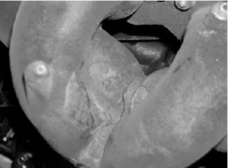
Fig.1 Crack failure of engine exhaust manifold
Considering the performance of anti-thermal fatigue and deformation of material under the condition of thermal shock, the exhaust manifold adopts the medium silicon-molybdenum heat resistant nodular cast iron material, and the formula and properties refers to GGV SiMo4.5 in German standard DIN1694-TL047[9]. Under the condition of room temperature (20℃), the tensile strength is 550 MPa, and the yield strength is 470 MPa. And under the condition of high temperature (700℃), it is respectively reduced as 72.7 MPa and 66.4 MPa[10].
1.1.Innerflowfieldanalysisofexhaustmanifold
The condition of bench simulation test is as the following. The transient control equation of inner flow field of exhaust manifold adopts compressible N-S equation, the turbulence model adopts standard k-ε model, the wall surface treats in accordance with standard wall surface function, and the catalytic converter adopts porous medium model. Under the above conditions assumed, the control equation of flow and heat-transfer equation is as the following.
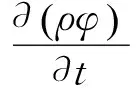
(1)
In which,ρis the density,φis the generalized variable,Uis the speed,Γφis the generalized diffusion coefficient, andSφis the singular source term.
Under the condition of the bench test, the test result of exhaust temperature of manifold is shown as in Fig.2, and the highest exhaust temperature is 843℃. The temperature boundary condition of exhaust manifold and wall of three catalytic is shown as in Fig.3. The highest temperature of the internal flow field of the three way catalytic converter reaches to 1 261℃, and the average temperature of exhaust manifold reaches about 1 200℃.
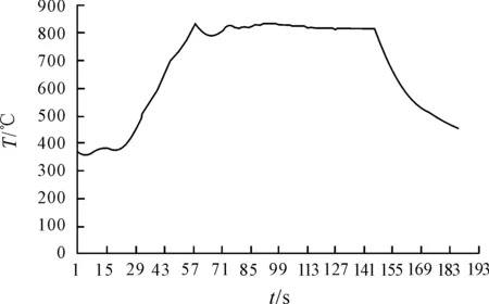
Fig.2 Temperature of manifold exhaust
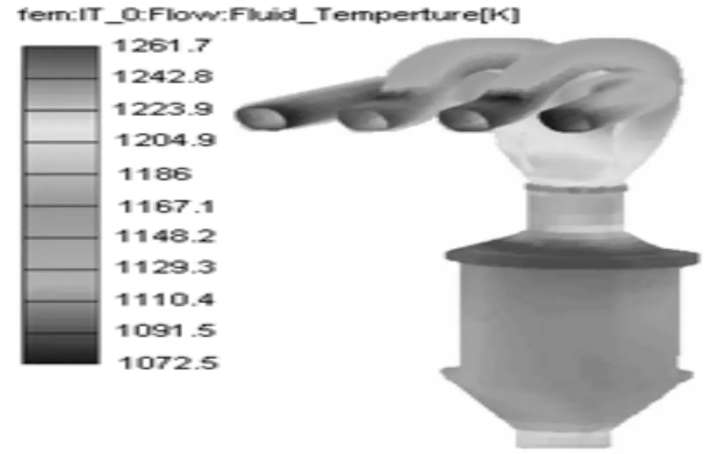
Fig.3 In-wall temperature field and heat exchange coefficient
1.2.Thermalfatigueanalysisofexhaustmanifold
The Fig.4 shows the assembly of exhaust manifold and the installing status. The entrance flange of exhaust manifold connects to cylinder cover through ten pieces of M10 screw bolt, and the exhaust manifold connects with three way catalytic converters through three pieces of M10 screw bolt, and the support of three way catalytic converters connects with cylinder body through two pieces of M10 screw bolt. The Fig.5 shows the finite element model of thermal fatigue analysis of exhaust manifold. The exhaust manifold itself adopts C3D10 of Two order tetrahedral elements, and the assembly of three way catalytic converters adopts C3D8 of hexahedron element, and also the simple cylinder and cylinder head model adopt C3D8 of hexahedron element. When it computes it makes constraint for three pieces of translational degree of freedom of cylinder body, four angles of the cylinder head and the bottom surface of cylinder body. The calculation condition simulates the experiment of thermal shock of exhaust shaft. It has to carry through analysis computation of thermal fatigue for the six cycles so as to get the stable thermal strain.
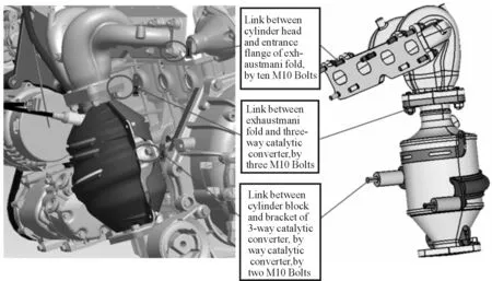
Fig.4 Status of installing for exhaust manifold
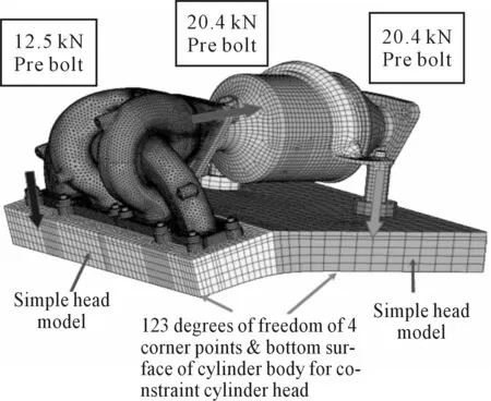
Fig.5 Finite element model of exhaust manifold
2.Analysis of computing result
The Fig.6 is the distribution of temperature field in steady state of exhaust manifold. The highest and lowest temperature is respectively 875℃ and 140℃, and the performance of selected material satisfies the design demand. If the temperature field is mapped into the internal surface of exhaust manifold, then through computing it can obtain the thermal stress of manifold shown as in Fig.7. The biggest thermal stress(516 MPa)of exhaust manifold is respectively located at the corner of airway root 1 and airway root 2, and under the condition of exceeding the room temperature, the yield limit of material probably results in plastic deformation. It is more than 60 MPa to the stress located at the position of manifold“V”shape, and it exceeds 75 MPa in local location. Therefore it exceeds the yield limit (66.4 MPa) of material under the condition of corresponding temperature (700℃), and even it exceeds the ultimate tensile strength (72.7 MPa) of material in local position.
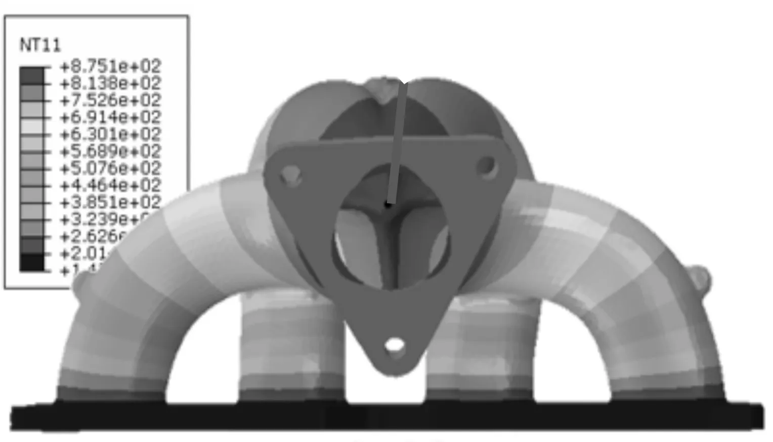
Fig.6 Temperature field of manifold
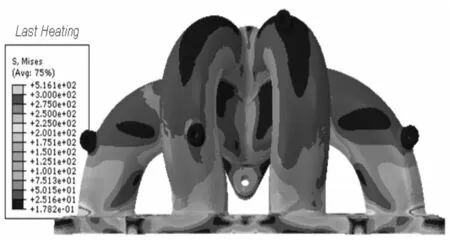
Fig.7 Thermal stress of manifold
The residual stress after cooling of exhaust manifold is shown as in Fig.8, and the biggest residual stress (756 MPa) presented to the position in“V”shape of manifold exceeds seriously the yield limit and ultimate tensile strength of material under the condition of corresponding temperature (20℃). And at the same time, the plastic strain amplitude (0.495) of exhaust manifold located at the position of “V”shape of manifold is also exceeds the design limit value (0.38) shown as in Fig.9.

Fig.8 Residual stress of manifold
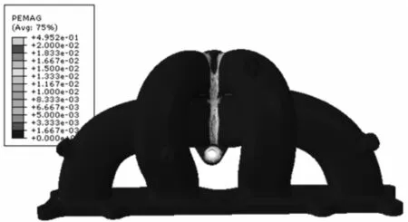
Fig.9 Plasticity strain of manifold
From the above result it can be seen that it puts up better homogeneity in analysis result of thermal stress and residual stress as well as plastic strain of exhaust manifold, and the position of cracking failure of engine exhaust manifold is accordance with that it appears in the bench test shown as in Fig.1. Therefore it can be considered that the thermal fatigue damage, resulted in lack of design in exhaust manifold structure, is to give rise to main cause of cracking failure of engine exhaust manifold. Because it is very sudden, undersize in filleted corner, and poorer in lateral stiffness of exhaust manifold to the connection transition (located at“V”shape position) between air passage of exhaust manifold in the original design, so it leads to that under the condition of temperature load impact the manifold produces a unacceptable stress concentration and finally forms the fissure. Therefore it is necessary to make the structure optimization for the above mentioned position.
3.Design of structure optimization for exhaust manifold
The enlargement of chamfer fillet located at“V”shape position of exhaust manifold can buffer its stress concentration. But it can bring about heterogeneous wall thickness and being large in local thickness for exhaust manifold, influence the casting quality of semifinished product, and make the rate of spoiled products in semifinished product increase, so it should keep the filleted corner to be invariant in the V”shape position. The Fig.10 shows the optimal design scheme of exhaust manifold, and it increases a piece of reinforcement between air passage 1 and air passage 4 as well as air passage 2 and air passage 3. And at the same time it heightens the original parting line to form a piece of reinforcement, and strengthens the “V”shape position of exhaust manifold. After increasing the reinforcement at“V”shape position of exhaust manifold, the thermal deformation at“V”shape position of exhaust manifold reduces, and the specific elongation of medium silicon-molybdenum vermicular graphite cast iron is lower than spheroidal graphite cast iron. Therefore it probably bring about the flange deformation enlargement of connected cylinder head, and it is incapable to ensure effective seal between exhaust manifold and cylinder head. So it has to cut off the flange of connected cylinder head and air admission in exhaust manifold from the middle of air passage 2 and air passage 3, and it remains a gap in the middle. The Fig.11 shows the thermal stress of exhaust manifold after structure optimization, and after optimization, it would be reduce by a big margin to the stress of each position of exhaust manifold. Although it exceeds the yield limit under corresponding temperature in local position, but generally it does not appear to exceed the status of tensile strength under corresponding temperature. The maximum thermal stress(520 MPa)produces similarly at the position of root fillet of air passage 1 and air passage 2, compared with original structure, the maximum thermal stress keeps basically the same level. But the stress of connected position (“V”shape position) between air passage of exhaust manifold reduces about 50~60 MPa, and it basically is controlled in the range of material yield limit under corresponding temperature.

Fig.10 Optimal scheme of manifold structure
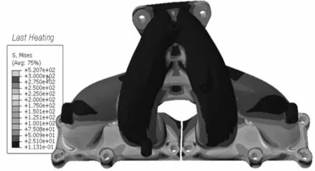
Fig.11 Thermal strain after optimization
After structure optimization, the residual stress distribution of exhaust manifold (Fig.12) is different from the residual stress distribution of the original structure, the maximum residual stress presents to the root segment of No.1 air passage and No.2 air passage. The maximum value from 756 MPa increases to 805 MPa. Probably it still results in cracking failure, and therefore it needs further to make the structure optimization. But the residual stress of“V”shape position of exhaust manifold drops down about 50~120 MPa, and it improves the concentration status of residual stress at “V”shape position of exhaust manifold enormously. The Fig.13 shows the plastic strain amplitude of optimal scheme of exhaust manifold, and its plastic strain value is under the plastic strain of original structure far and away. Therefore it satisfies the design demand of plastic deformation of the material.
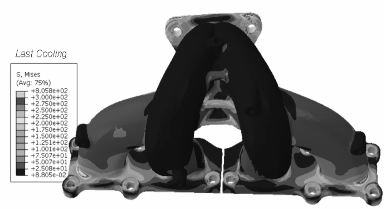
Fig.12 Residual stress after optimization
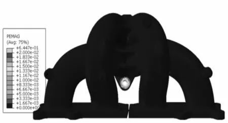
Fig.13 Plasticity strain after optimization
After making the qualified sample piece according to scheme of optimal design, it successively makes lots of reliability experiment validation. And after experiment accomplishing, through the inspection it finds that there is not any problem of oxidation of delamination in the exhaust manifold, and the surface of exhaust manifold is not any fissure. After completing the alternating load test for 400 hour, the exhaust manifold is shown as in Fig.14. From the Fig.14, it can be seen that there is not any fissure in the surface and its interior, and it shows that the optimal design scheme of the exhaust manifold is reasonable.
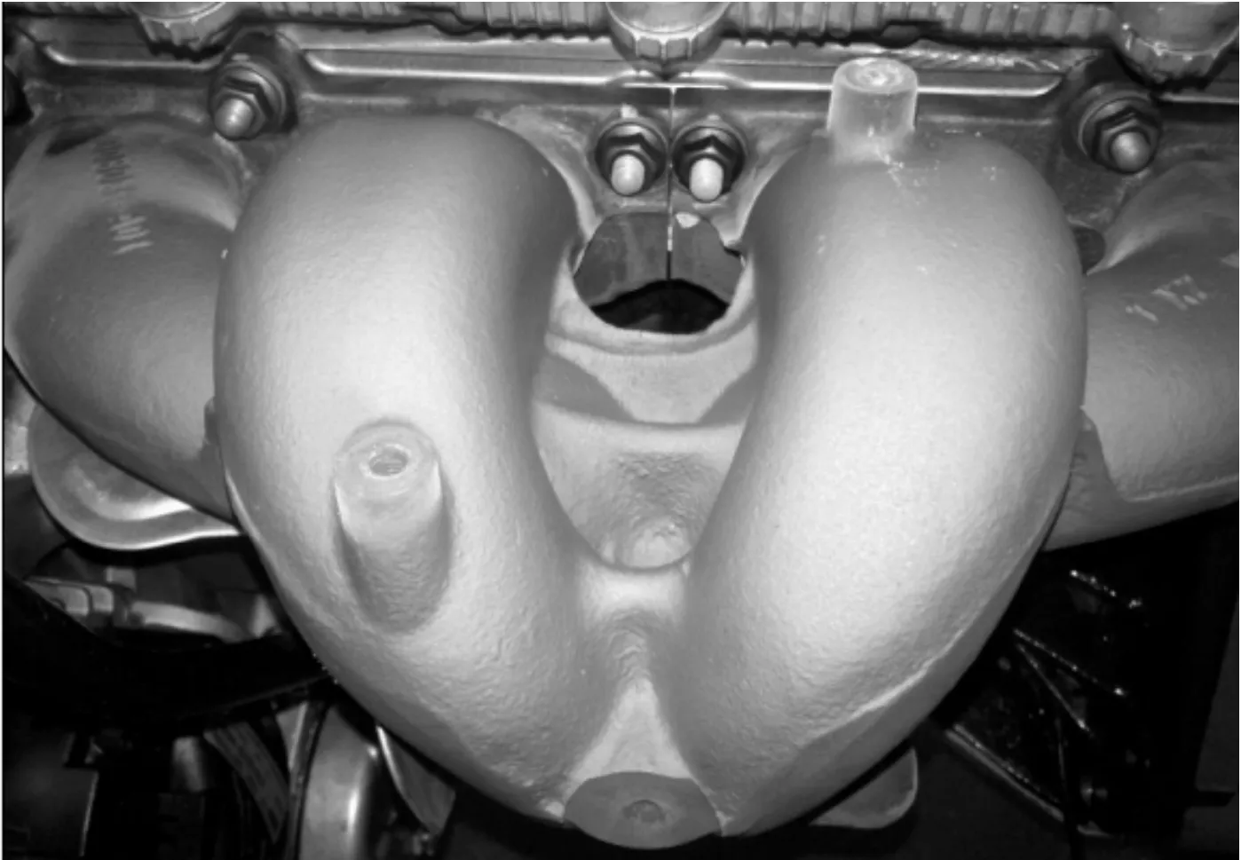
Fig.14 Exhaust manifold after fatigue test
4.Conclusions
Aimed at the crack failure of exhaust manifold for a certain type of engine, it built the analytical model of thermal stress of engine exhaust manifold, and analyzed the thermal stress, residual stress and plasticity strain of manifold under the action of cold and thermal shock load. The analysis result demonstrated that the main cause, which resulted in cracking failure of exhaust manifold, would be that each index located at manifold “V” shape position always is higher than the design extreme. Based on the above analysis result, it proposed the solution of optimal design, by means of the methods such as reinforcement at the “V” shape position, subdivision of connection position in outside surface and so on, it improved the status of stress concentration of “V” shape position. The experiment result shows that the proposed optimal solution is reasonable and feasible.
[1] Xiate G Y. The Heat Transfer and Heat Load of Internal Combustion Engine[M].Beijing:China Agricultural Machinery Press,1981.
[2] GUO Quanling,ZHAO Xinwu.Recommended Working Temperature Summarization of Different Cast Iron Grades Used for Engine Exhaust Manifolds[J].Machinability and others,2011(2):82-85.
[3] WU Guigen,PENG Donghua,LU Ping.Failure analysis of engine exhaust manifold wall[J].HEAT TREATMENT OF METALS,2011,36(9):90-92.
[4] LI Longchao,XU Tao.The Thermal-structure Coupled Analysis on Exhaust Manifold of a Certain Diesel Engine[J].Auto Engineer,2011(3):55-57.
[5] SUN Liwang,ZHU Qingshan,HOU Xianjun,et al.Analysis of thermal stress for engine exhaust manifold based on direct fluid-solid coupling[J].Journal of Henan Agricultural University,2012,46(2):81-84.
[6] Wang Hui,Li Longchao,Yao Wei.Application of CFD & FEA Coupling Analysis in Solving Thermal Deformation of Exhaust Manifold[J].SMALL INTERNAL COMBUSTION ENGINE AND MOTORCYCLE,2012,41(3):15-17.
[7] DENG Banglin,LIU Jingping,YANG Jing,et al.Thermal Stress Analysis of Gasoline Engine Exhaust Manifold Based on Two-Way FSI[J].Transactions of CSICE,2011,29(6):549-554.
[8] CAO Yuanfu,YANG Zhenyu,KE Yan.Simulation and Experimental Study on the Thermal Loads of Exhaust Manifold[J].Automotive Engineering,2012,34(5):418-422.
[9] JIN Yongxi.Discussion About Material and Technique of Si-Mo Heat-Resistant Vermicular Iron Exhaust Manifold[J].FOUNDRY,2005,54(12):1238-1244.
[10] LI Xiuzhen,YU Huashun,LIU Taiqiang,et al.Study on Medium-silicon Heat-resistant Compacted Graphite Iron and Its Application[J].FOUNDRY,1997(2):18-20.
发动机排气歧管结构的优化设计
毛文群
岳阳恒立冷气设备股份有限公司,湖南 岳阳 414000
开裂失效是发动机排气歧管典型的失效模式之一。为了找出失效原因并改进发动机排气歧管结构,研究了发动机排气歧管结构的优化设计。构建了发动机排气歧管热应力分析模型,研究了歧管在冷热冲击条件下开裂的失效机理,基于降低歧管关注位置的热应力和残余应力与塑性应变,提出了排气歧管结构的优化设计方案。仿真实验分析显示,在歧管“V”形位置处的各项指标在冷热冲击载荷作用下,其热应力、残余应力和塑性应变均高于设计极限值,是导致歧管开裂失效的主要原因。借助在“V”形位置加筋及外表面连接位置剖分等技术措施,可改善应力集中状况。实验结果验证了该排气歧管优化设计方案的合理性与有效性。
排气歧管;温度场;热应力;结构优化
U464
2012-10-25
*MAO Wenqun.E-mail:warkins@163.com
10.3969/j.issn.1001-3881.2013.06.024
猜你喜欢
杂志排行

机床与液压的其它文章
- Research and Realization of the Control System for Cement Screw Packing Machine Based on MCGS and S7-200PLC
- The Analysis and Countermeasure of Centrifugal Atomizer Nozzle Block Up
- Static and Dynamic Characteristic Analysis for Vehicle MRF Damper
- Multi-physics Coupling of Hydraulic System
- Research of Production Configuration Management Based on the Internet of Things-mixed Cloud Enterprise
- Research and Design of Embedded Serial Device Server on the DNC System