The Analysis and Countermeasure of Centrifugal Atomizer Nozzle Block Up
2013-12-07DINGYouqing
DING Youqing
Chongqing University of Science and Technology, Chongqing 401331, China
TheAnalysisandCountermeasureofCentrifugalAtomizerNozzleBlockUp
DING Youqing*
ChongqingUniversityofScienceandTechnology,Chongqing401331,China
WTE(wastetoenergy)isoneoftheidealmethodstodealwithMSW(MunicipalSolidWastes).Butitwillbringsecondarypollutionintheprocessofcombustion.Therefore,theflugasfromWTEplantmustbetreatedthroughgaspurificationsystem.Inordertoprotectenvironment,thecentrifugalhigh-speedatomizerisusedinplanttodesulfurandpurifyflugas.Itisthekeyequipmentofgaspurificationsystem.Inthispaper,thecauseofcentrifugalatomizernozzleblockuphasbeenanalysedspecificallyandthesuggestionofcountermeasurehasbeengiven.
atomizer,WTE,nozzle,blockup
1.Introduction
The centrifugal high-speed atomizer is the key equipment in the field of environmental protection industry such as chemical industry, pharmacy, food, environmental protection. In the field of air pollution controlling, the centrifugal high-speed atomizer is used for desulfuration in the power plant and for the flue gas treatment in the WTE plant. In recent years, the centrifugal high-speed atomizer has gotten broader application in China with the fact of the development of the WTE industry and the broad set-up of WTE plant. The working principle of the centrifugal high-speed atomizer is: the high-speed electric motor drives the atomizing plate running at high speed; the atomizing plate produces powerful centrifugal force; the turbid liquid or emulsion form material is atomized to the micron level dimension and thereby has been blown out through a peculiar nozzle. After atomizing, the liquid drop has big superficial area, which is more beneficial to the heat transition and reaction with others. Therefore, the flue gas can be eliminated effectively.
Fig.1 indicates the purifying principle of flue gas in WTE plant. The system mainly consists of the centrifugal high-speed atomizer, the reaction tower, the dry chamber, and the bag filter. After absorbed heat by the boiler, the flue gas is induced to the dry chamber.Simultaneously, the centrifugal high-speed atomizer blows out Ca (OH)2fog (lime seriflux) into the tower. On the one hand, the Ca (OH)2fog has chemical reactions with the acerbic flue gas such as SO2, HCL and generate solid product. In addition, the heat of flue gas is transferred to the absorbent and dries the Ca (OH)2fog. After reaction in the tower, the product is solid and has been delivered out from the bottom of tower. The flue gas passes through the bag filter and then enters the atmosphere. And the particulate dust forms bottom ash.
2.Centrifugal high-speed atomizer structure
Fig.2 illustrates the structure of centrifugal high-speed atomizer. The mechanical system of centrifugal high-speed atomizer mainly includes driving system, atomizing system and material supplying system.
2.1.Thedrivingsystem
The driving system is composed of two parts: one is the motor and its supplying part and the other one is the needle bearing. The output of the motor is connected with the shaft by elastic coupling. It can compensate any tiny unbalance from the plate and the fluctuation from supplying system.
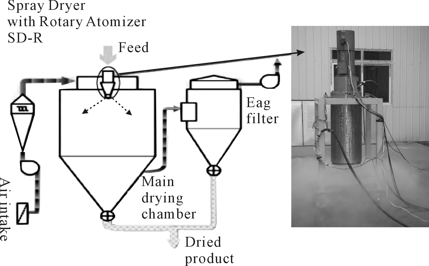
Fig.1 The purifying principle of flue gas in WTE plant
2.2.Theatomizingsystem
The atomizing system is composed of the flow distributor and the plate. The distributor distributes the lime slurry into the plate. The plate runs at high speed with the driving shaft. The lime slurry has been jetted out through nozzles and forms tiny liquid-drop.
2.3.Thesupplyingsystem
The supplying system is to supply lime slurry with suitable water contents and cooling water.
The centrifugal high-speed atomizer is assembled on the top of the drying tower by a baseplate. The lime slurry pipe and the cooling water pipe are connected to the baseplate. The baseplate divides centrifugal high-speed atomizer into two major parts. the gear box and the motor are above the baseplate and the distributor, and the atomizing plate supplying pipe is under the baseplate. All above parts are easy for the operator to examine and repair. All parts under the baseplate are in the tower and contact with flue gas directly. For protecting the parts from corrosion, all parts have been sealed within cylindrical cover except the atomizing plate.
3.Atomizing system
Fig. 3 shows the nozzle structure. The atomizing system mainly includes two components: the atomizing plate and the distributor. To guarantee the liquid-drop even, the atomizer should meet following conditions: ① The centrifugal force must be greater than the gravity, ② There is no vibration when the plate is running, ③ The liquid amount is assigned very evenly, ④ The surfaces of plate and pass must be smooth and clean.

1.atomizing plate, 2.cylindrical cover, 3.baseplate, 4.coupling, 5.Pipe, 6.motorFig.2 Centrifugal high-speed atomizer structure
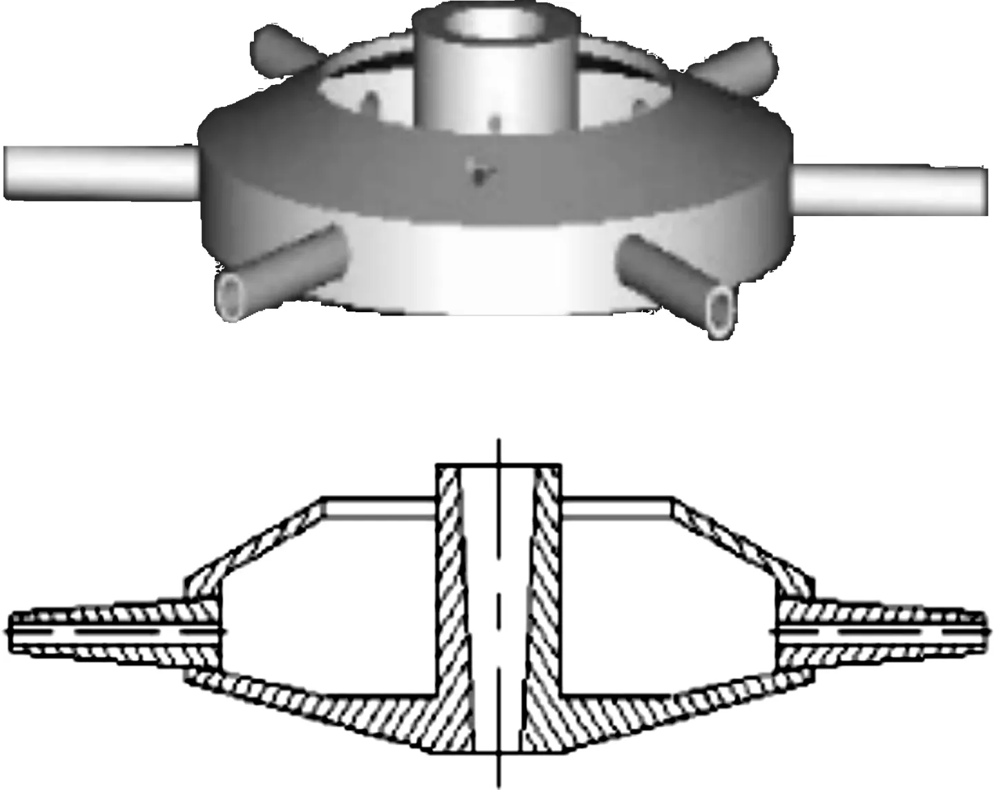
Fig.3 Nozzle structure
4.The analysis of centrifugal atomizer nozzle block up
Fig. 4 illustrates the effect of air draw within plate. With the high speed, the plate pushes the air to the outside and a low pressure appears on the surface of plate. The air from the nozzle draws out the air just below the plate and produces back-flow. So the dry air enters this area. The hot-air ia sucked into the gap between the upper surface of the plate and the cover, and partly dries the lime slurry. Some of the fog droplets are taken to the gap by air current also. Therefore, the semi-dry lime slurry deposits in metal surface. It will be dry and even burn under the hot-air environment. Furthermore, the fog droplet and air have sufficient power. It will mix with the outside air and form the eddy under the plate. It is possible to form deposit under the plate. Air draw is the main cause of energy consumption. This energy consumption is greater than that of atomizering. For small size atomizer, the energy consumption of air draw is especially notable comparing with atomizing required energy consumption. Design must diminish the effect of air draw.
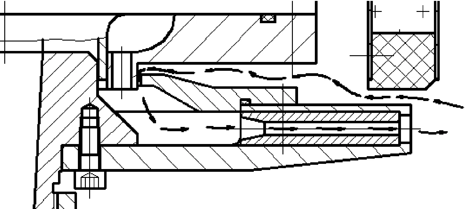
Fig.4 The effect of air draw within plate
In the case of closing down, the semi-dry lime slurry will solidify and form block because the semi-dry lime slurry is stop in the nozzle and the ambient temperature is about 200 centigrade.
5.Conclusions
When the nozzle is blocked up, the plate will lose dynamic balance. And it will cause vibration to the atomizer. The atomizing effect will be reduced greatly. Clearing nozzle becomes hard work.
From the analysis above, the countermeasure to deal with the nozzle block are below:
1) The gap between atomizering plate and protection cover should be small. At the same time, in order to avoid collision or friction, the gap should not be too small. For example, it is 3 millimeters.
2) Sending cold air within the cover to cool the inside of atomizer and to ensure the high pressure within cover. It prevents the air from entering the atomizer from the gap between atomizing plate and cover.
3) The cross section size of the nozzle should be designed according to that liquid flow is full of nozzle.
4) When the atomizer is stop, the nozzle should be passed by clean water.
[1] GUO Yi,WANG Xi.Dry Spraying[M].Beijing: Chemical industry press,1983.
[2] YANG Chengyun,LIN Tengjiao,LI Runfang.The Inherent Characteristics Analysis and Dynamic Response Analysis of the Speed-up Box System[J].China Mechanical Engineering,2003,14(5):380-382.
[3] Misellati M M.Liquid Distribution and Flow in Rotary Atomizers[D].USA:University of Wiseomin-Madison,1984.
高速离心雾化器喷嘴堵塞原因分析及对策
丁又青*
重庆科技学院,重庆 401331
垃圾焚烧发电是城市生活垃圾处理的最理想方式,但是它将产生二次污染,因此,必须对烟气进行净化处理,而高速离心雾化器就是用在烟气净化处理中的关键装备。针对高速离心雾化器在使用过程中其喷嘴容易堵塞的现象进行了分析,并提出了解决方案。
雾化器;垃圾焚烧发电;喷嘴;堵塞
TH13
2012-12-09
*DING Youqing, Professor.E-mail: dingyouqing@msn.com
10.3969/j.issn.1001-3881.2013.06.001
猜你喜欢
杂志排行
机床与液压的其它文章
- Research and Realization of the Control System for Cement Screw Packing Machine Based on MCGS and S7-200PLC
- Static and Dynamic Characteristic Analysis for Vehicle MRF Damper
- Multi-physics Coupling of Hydraulic System
- Research of Production Configuration Management Based on the Internet of Things-mixed Cloud Enterprise
- Research and Design of Embedded Serial Device Server on the DNC System
- A Weight-based Optimization Method of Lockup Quality for an Automotive Hydrodynamic Torque Converter