Static and Dynamic Characteristic Analysis for Vehicle MRF Damper
2013-12-07YANZhanhuiGUANTieying
YAN Zhanhui, GUAN Tieying
School of Mechatronics Engineering, Changchun Institute of Technology, Changchun 130012, China
StaticandDynamicCharacteristicAnalysisforVehicleMRFDamper
YAN Zhanhui*, GUAN Tieying
SchoolofMechatronicsEngineering,ChangchunInstituteofTechnology,Changchun130012,China
AnMRFdamper’smechanicalstructurewasputforwardbasedonitsworkingprinciple,anditsweaklinkswerefoundoutbyFEM.Moreover,thispaperanalyzedthestaticanddynamiccharacteristicsandoptimizedthemechanicalstructure.Thepre-optimizedandpost-optimizedsimulationresultsshowedthatthevibrationamplitudevalueofdampergotdecreasedby35%whenthelowfrequencysparkexists,anditprovidesabasisforthenewtypevehicleMRFdamper’sdesign.
MRFdamper,staticcharacteristic,dynamiccharacteristic
1.Introduction
Magnet-Rheological Fluid (MRF) is a new intelligent engineering material, it can change from liquid to solid or from solid to liquid at moment (<10 ms), and vary widely, so it can be used in designing some new type dampers[1-4] and improving security and stability of suspension system. Automobile manufacturers and research institutions put a new premium on research of MRF damper, and conducted relevant theories and experimental researches, it mainly includes: 1) Strengthen research on MRF rheology mechanism, build up and revise simple and practical false static force model and dynamics hysteresis model; Research intelligence control theory and its application for MRF model in terms of special circumstance of structure vibration. 2) Research and improvement of MRF rheology hysteresis characteristic, energy-consumed characteristic, power response and its effect characteristic and heat dissipation performance, bring forward widespread reference and comparison criterion in view of it, deeply analyze MRF compressibility and its hysteresis characteristic, shearing force-velocity and oil-gas mixture owing to desaturation (densification) effect. 3) Research new stabilizer and its application to MRF.
It is still at an elementary study stage for the field in China, so to research design principle and experiment deeply, develop MRF damper of performance quality, moderate price, it is a key to application and is of important meaning to develop intelligent suspension system[5-8].
To apply MRF damper to vehicle industry, this paper adopted JETTA damper’s join dimension and external structure[9-15], based on designed damper (as shown in Fig.1), the weak links were found out by FEM. The mechanical structure has been optimized and the static and dynamic characteristics are analyzed. The simulation provides a basis for new type vehicle MRF damper’s design.
2.Static characteristics analysis of MRF dam-per
Cylinder rod’s mechanical property of MRF damper is not the most reasonable during life expectancy, therefore find out weak link during design stage, and optimize it; it can effectively improve cylinder rod’s mechanical property and life expectancy.
According to above-mentioned analysis, analyze and simulate damper’s important parts, such as cylinder, cylinder rod. In order to simplify stress, mutual agreement are as follows: damper’s end hanging ears are in same plane, and they are in pressed stress or pulled stress, damper’s installation way is one end is fixed, the other is hinged.
Line excitation force is conducted during simulation, measured some data. Constructed model is shown in Fig.2.
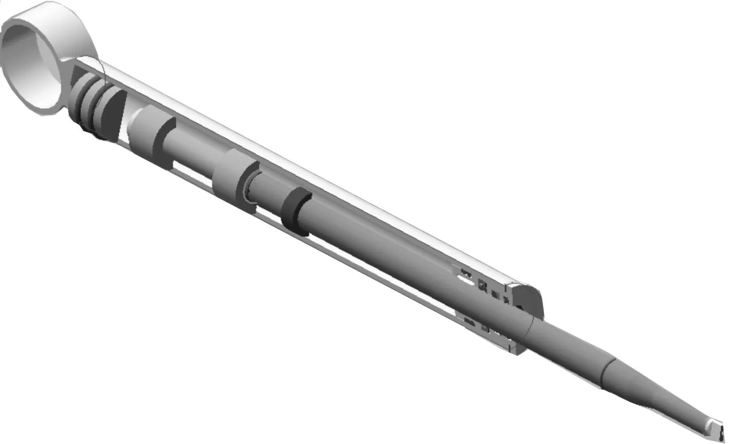
Fig.1 Three dimension MRF damper
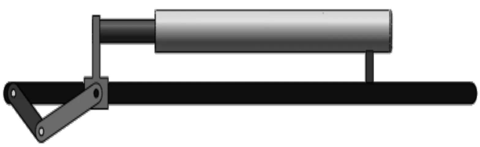
Fig.2 Damper stress simulation model
2.1.Material
45﹟ high quality carbon steel, its volume is 0.000 134 6 m3. Element attribute is solid grid, it is divided into 6 014 elements, 10 040 nodes, and cylinder rod’s FEM grids are showed in Fig.3.
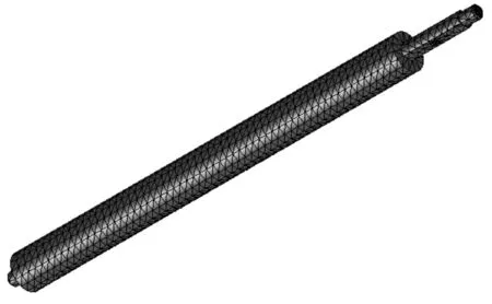
Fig.3 Cylinder rod’s FEM grids
2.2.Loadandconstraint
Alt-remote loads-4-1〈cylinder rod -1〉: load(direct transform)applied to 1 plane is -1.182 1e-12 N, torque is 0.020 687 N·m, force is -0.430 98 N in directionX, torque is 0.037 849 N·m, force is -1.869 3e-16 N in directionY, torque is 2.425 1e-17 N·m, mass is 0 kg inZdirection, its position is (0.001 468 35 m, 0.061 146 8 m, 0.664 144 m), corresponding inertia momentum is (0, 0, 0, 0, 0, 0) kg·m2.
Alt-remote loads-4-2〈cylinder rod -1〉: load(direct transform)applied to 1 plane is 5.267 8e-15 N, torque is -4.379 3e-16 N·m, force is -1.409 5e-14 N in directionX, torque is 1.313 8e-015 N·m, force is 63.112 N in directionY, torque is 3.299 7e-031 N·m, mass is 0 kg inZdirection, its position is (0.002 068 06 m, 0.046 146 8 m, 0.664 144 m), corresponding inertia momentum is (0, 0, 0, 0, 0, 0) kg·m2.
Alt-remote loads-4-3〈cylinder rod -1〉: load(direct transform)applied to 1 plane is 1.716 2e-12 N, torque is -0.059 924 N·m, force is 3.994 9 N in directionX, torque is 2.634e-13 N·m, force is 8.922 1e-16 N in directionY, torque is 5.630 7e-17 N·m.
Alt-remote loads-4-4〈cylinder rod -1〉: load(direct transform)applied to 1 plane is -3.508e-15 N, torque is 2.916 3e-15 N·m, force is 9.386 3e-15 N in directionX, torque is 6.288 2e-16 N.m, force is -42.028 N in directionY, torque is -1.029 8e-31 N·m, mass is 0 kg inZdirection, its position is (0.001 468 35 m, 0.061 146 8 m, 0.314 144 m), corresponding inertia momentum is (0, 0, 0, 0, 0, 0) kg·m2.
2.3.Results
Tab.1 shows the endured stress of cylinder. Tab.2 shows the synthesized displacement of cylinder. Fig.4 shows a stress distribution diagram, and Fig. 5 shows the cooperative displacement. Based on all these simulation results, it could see that the weakest position of cylinder is at the root of cylinder and the maximum stress is up to 6 MPa. Therefore, after strengthening treatment, it can meet the application requirements.
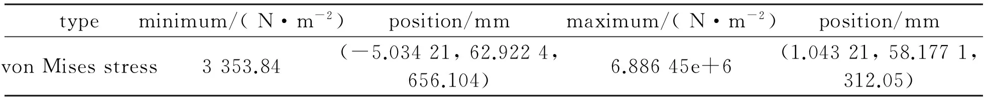
Tab.1 Cylinder’s endured stress
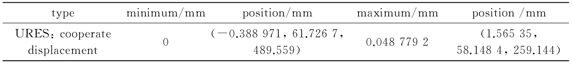
Tab.2 Cylinder’s cooperate displacement
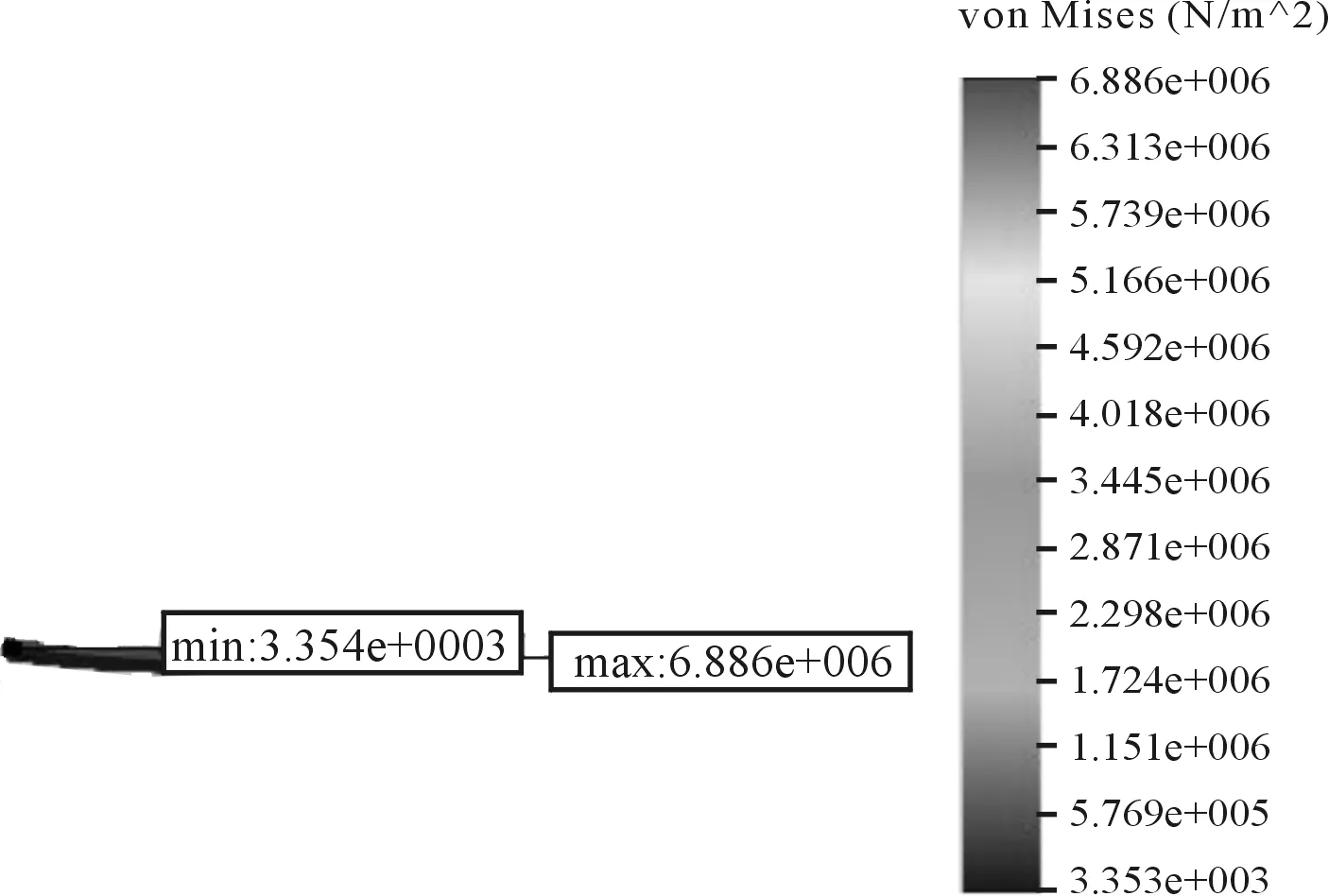
Fig.4 Stress distribution (deformation proportion 831.842)
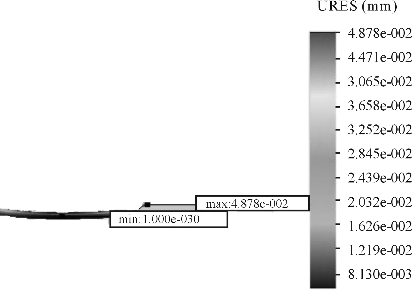
Fig.5 Synthesized displacement (deformation proportion 831.842)
3.Dynamic characteristics analysis of MRF damper
The function of vehicle damper is mainly to amortize and absorb the vibration, to degrade its jounce and improve steering smooth. Therefore, the vibration characteristic, such as horrent frequency, directly affects vehicle’s performance. Generally speaking, the vibration frequency of a person’s body is about 1.6 Hz in natural status and the ideal resonance frequency of chassis is also about 1.6 Hz. Combined with actual chassis vibration model, a slider-crank incentive model is established, and the simulation of vehicle damper frequency is set to 1.6 Hz, namely, in the experimental stage, assume that slider-crank mechanism drive is 100 r/min, chassis amplitude is as one evaluation index of vehicle, its model is as shown in Fig.6.
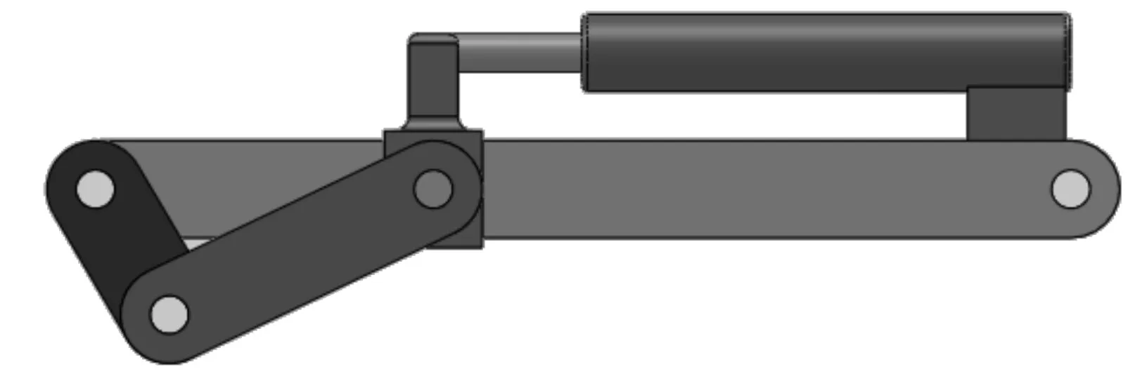
Fig.6 Damper’s low frequency vibration simulation
3.1.Material
It is showed in Tab.3.
3.2.Loadandconstraint
Alt-remote loads-7-1〈03 slider-1〉: load(direct transform)applied to 1 plane is 0 N, torque is -2.304 2e-17 N.m, force is 26.572 N in directionX, torque is 2.100 6e-16 N·m, force is 5.699 e-15 N in directionY, torque is -4.358 5 N·m,mass is 0 kg inZdirection, its position is (0.203 407 m, 0.039 348 6 m, 6.938 89e-18 m), corresponding inertia momentum is (0, 0, 0, 0, 0, 0) kg·m2.
Alt-remote loads-7-2〈03 slider-1〉: load(direct transform)applied to 1 plane is -35.123 N, torque is -0.257 91 N·m, force is -1.700 4 N in directionX, torque is 1.249 N·m, force is 5.699e-15 N in directionY, torque is -1.155 9e-13 N·m,mass is 0 kg inZdirection, its position is (-0.111 862 m, 0.049 348 6 m, 0.044 m), corresponding inertia momentum is (0, 0, 0, 0, 0, 0) kg·m2.
Alt-remote loads-7-3〈03 slider-1〉: load(direct transform)applied to 2 plane is -1.527e-22 N, torque is -6.650 4e-23 N·m, force is 4.151 7e-23 N in directionX, torque is 2.269 8e-16 N·m, force is 2.997 1e-015 N in directionY, torque is -2.556 4e-32 N·m, mass is 0 kg inZdirection, its position is (-0.012 295 3 m, 0.119 349 m, 0.012 m), corresponding inertia momentum is (0, 0, 0, 0, 0, 0) kg·m2.
Alt-remote Loads-7-4〈03 slider-1〉: load(direct transform)applied to 1 plane is 29.64 N, torque is 1.647 8 N·m, force is -18.309 N in directionX, torque is 2.667 5 N·m, force is -3.559 1e-15 N in directionY, torque is -1.032 9e-8 N·m,mass is 0 kg inZdirection, its position is (-0.035 667 6 m, 0.119 349 m, -0.08 m), corresponding inertia momentum is (0, 0, 0, 0, 0, 0) kg·m2.
Alt-remote loads-7-5〈03 slider-1〉: load(direct transform)applied to 1 plane is 0.903 6 N, torque is 0.086 511 N·m, force is -1.081 4 N in directionX, torque is 0.072 288 N·m, force is -1.358e-16 N in directionY, torque is -2.732 9e-17 N·m,mass is 0 kg inZdirection, its position is (-0.035 667 6 m, 0.119 349 m, -0.08 m), corresponding inertia momentum is (0, 0, 0, 0, 0, 0) kg·m2.
Alt-remote loads-7-6〈03 slider-1〉: load(direct transform)applied to 1 plane is 8.258 7e-24 N, torque is 0 N·m, force is 6.133 3e-24 N in directionX, torque is 0 N·m, force is 3.688 7e-7 N in directionY, torque is 0 N·m, mass is 0 kg inZdirection, its position is (-0.044 361 8 m, 0.119 349 m, 0.02 m), corresponding inertia momentum is (0, 0, 0, 0, 0, 0) kg·m2.
3.3.Elementattribute
Entity grid, 782 6 elements, 134 57 nodes.
3.4.Results
Tab.4 and Tab.5, Fig. 7 and Fig. 8 are the simulation results, and they show that chassis vibration amplitude is about 2.6mm which is less than 4 mm when the excitation frequency is less than 1.6 Hz, it shows that the assigned parameters are reasonable.
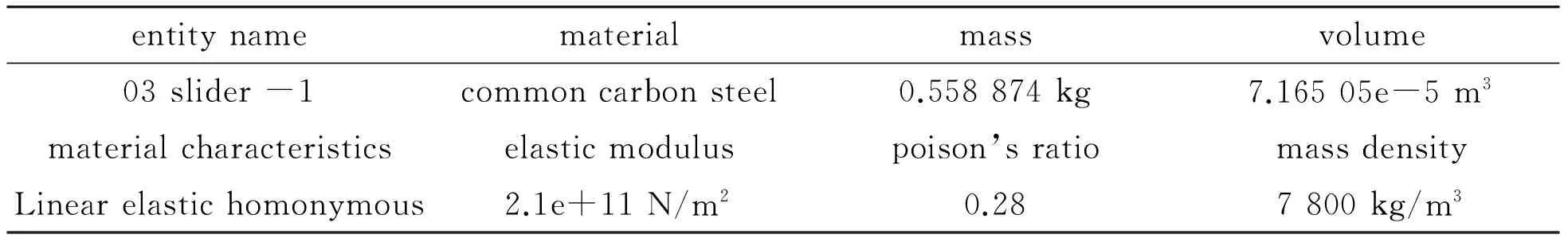
Tab.3 Cylinder’s material attributes
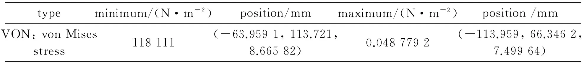
Tab.4 Cylinder’s endured stress
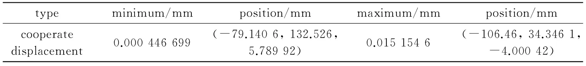
Tab.5 Cylinder rod cooperate displacement
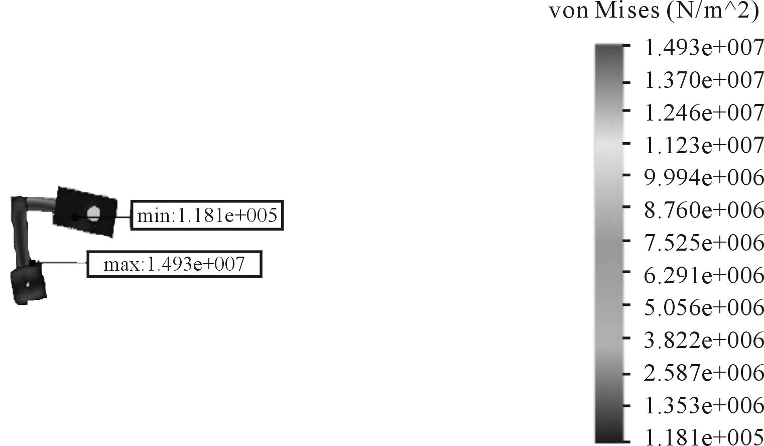
Fig.7 Cylinder rod stress (deformation proportion 884.58)
4.Conclusions
The weakest position of cylinder rod is at the end part of axis, the maximum stress is up to 6 MPa through the simulation data, it can meet the requirements after the intensifying treatment. The design structure was optimized.
Simulation results show that chassis vibration amplitude is about 2.6 mm which is less than 4 mm when the excitation frequency is less than 1.6 Hz, it shows that the assigned parameters are reasonable.
[1] Rabinow.The magnetic fluid clutch[J].AIEE Transactions,1948,67:1308-1315.
[2] Kavlicoglu B,Gordaninejad F,Evrensel C.A semi active,high torque,magnet-orheological fluid limited slip differential clutch[J].J Mater Sci Eng,2005,180:37.
[3] JIANG D S,Richard O.ntelligent materials and devices,structure and application[M].Wuhan: Wuhan University of Technology Press,2002.
[4] DU S Y.Intelligent materials system and structure[M].Beijing: Science press,2001.
[5] Liao C R,Chen W M,Yu M.Issues in Design Rules of a Magnetorheological Fluid Shock Damper for Automobile[J].China Mechanical Engineering,2002,9:723-726.
[6] Linder J E,Dimock G A,Werely N W.Design of A Magneto-rheological Automotive Shock Damper[C] //SPIE,2000:426-437.
[7] Vavreck A.Control of a Dynamic Vibration Damper with Magneto-rheological Damping[C]//SPIE,2000:252-263.
[8] Mark R J,Jonathan W B,Carlson J D.Properties and Applications of Commercial Magneto-rheological Fluids[C]//SPIE,1998:262-275.
[9] LI L Q,YAN Z H,LI X D.Design for a New Type Automobile MRF Damper[C] //The Third International Symposium on Traffic Information and Logistic Engineering,2010(1):409-412.
[10] Worden K.Data processing and experiment design for the restoring force surface method[J].Mechanical Systems and Signal Processing,1990,4:295-319.
[11] Cafferty S,Worden K,Tomlinson G.Characterization of automotive shock dampers using random excitation[J].Journal of Automobile Engineering,1995,9:239-248.
[12] Schiehlen W,HU B.Spectral simulation and shock damper identification[J] .International Journal of Non-Linear Mechanics,2003,38:161-171.
[13] Tallec P L,Mouro J.Fluid structure interaction with large structural displacements[J] .Computer methods in applied mechanics and engineering,2001,190:3039-3067.
[14] ZHOU C C,ZHENG Z Y,GU L.Study on the availability opening size of throttle and affection to the velocity characteristic of shock damper[J].Journal of Beijing Institute of Technology,2007,16:23-27.
[15] Duym S.Simulation tools,modeling and identification for an automotive shock damper in the context of vehicle dynamics[J].Vehicle System Dynamics,2000,33:261-285.
汽车磁流变减振器的静动态特性分析
闫占辉*,关铁鹰
长春工程学院 机电学院, 长春 130012
根据磁流变减振器的工作原理,提出一种汽车磁流变减振器的机械结构。利用FEM方法寻求机械结构的薄弱环节,优化了磁流变减振器的机械结构,并对其静态和动态特性进行了分析。优化前后对比结果表明,减振器的振动幅度减小35%左右,为新型磁流变液减振器的设计奠定了基础。
磁流变减振器;静态;动态
U463.335.1
2013-01-10
Sponsored by the Development Project of Jilin Provincial Department of Science and Technology(20090543)
*YAN Zhanhui, Professor. E-mail: yan-zhanhui @sohu.com
10.3969/j.issn.1001-3881.2013.06.002
猜你喜欢
杂志排行

机床与液压的其它文章
- Research and Realization of the Control System for Cement Screw Packing Machine Based on MCGS and S7-200PLC
- The Analysis and Countermeasure of Centrifugal Atomizer Nozzle Block Up
- Multi-physics Coupling of Hydraulic System
- Research of Production Configuration Management Based on the Internet of Things-mixed Cloud Enterprise
- Research and Design of Embedded Serial Device Server on the DNC System
- A Weight-based Optimization Method of Lockup Quality for an Automotive Hydrodynamic Torque Converter