Design and Research on the Length of Piston’s Buffer Oil Mat Area of a New Type of Hydraulic Rock Drill
2013-12-07WANShengXIEXiaoli
WAN Sheng, XIE Xiaoli
Sichuan Engineering Technical College, Deyang 618000, China
DesignandResearchontheLengthofPiston’sBufferOilMatAreaofaNewTypeofHydraulicRockDrill
WAN Sheng*, XIE Xiaoli
SichuanEngineeringTechnicalCollege,Deyang618000,China
Forthecomplicatedworkingconditionsofrockdrills,suchasacrackintherock,unevenhardnessofrockandimproperoperation,thepistonofrockdrillisunabletohitsteelchiseltailpromptly.Therefore,theemptyhittingphenomenonappears.Toavoidthisphenomenon,itisnecessarytodeducelengthofthepistonbufferoilmatarea.Accordingtoconstantdecelerationbufferstagemotionandvariabledecelerationbufferstagemotionofthepistonforanewhydraulicrockdrill,thepistondynamicsequationswerelistedseparatelyinthispaper.Furthermore,piston’smovingvelocityandaccelerationformulasarederivedduringitsemptyhittingbufferstage.Andthedesignandcalculationmethodofthelengthofpiston’sbufferoilmatareaisobtained.
newtypeofhydrauliccrockdrill,impactpiston,thelengthofpiston’soilmatarea
Percussive rock drill is important equipment in mining and quarrying. With the development of extractive industries, working behavior of hydraulic drill machine is in an increasingly high demand[1-4]. Compared with automatic reversing device of traditional hydraulic drill machine, the new type of hydraulic drill machine has two-position two-way hydraulic controlled reversing valve and two-position four-way hydraulic controlled reversing valve, which is connected with two-position two-way solenoid valve, pressure relief valve, pressure reducing valve, restrictive valve and check valve successively. The advantages of this kind of drill machine’s plunger tip are that the direction commutation is nimble, reliable, high frequency, quick reposition. And the plunger tip also can achieve self adaptive control under different operation conditions such as clay, rocks, sandstone. Besides, it has the features of high efficiency and low energy consumption. Based on the operating environment of the new hydraulic drill machine, the paper gives the length of piston’s buffer oil mat area, which is determined to avoid the empty hitting.
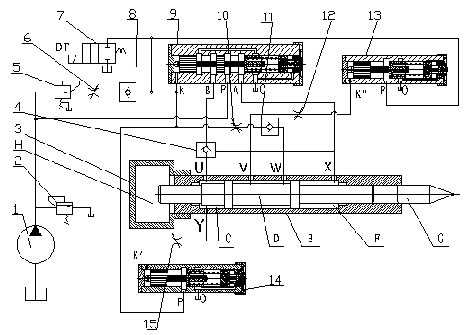
1.hydraulic pump,2.relief valve,3.impact mechanism, 4.hydraulic control one-way valve,5.pressure-reducing valve,6,10,12,15.throttle valve,7.two-position two-way solenoid valve,8,11.check valve, 9.two-position four-way hydraulic controlled reversing valve,13,14.two-position two-way hydraulic controlled reversing valve
Fig.1 Operating principle of the impact mechanism of a new hydraulic drill machine diagram
1.Operating principle of the impact mechanism of a new hydraulic drill machine
The two-position hydraulic controlled reversing valve, which is equipped in the plunger chip of new type hydraulic automatic reverse working device, come from patent ZL03134568.9. The operation principle of the patent will not be mentioned in this paper. Operation principle of the impact mechanism of the new hydraulic drill machine is shown in Fig.1. In the initial state, the impact pistonDis located at right side displacement by acting force ofHcavity gas spring. Pump 1 outlet in main oil system is connected with outletPof two-position four-way hydraulic controlled reversing valve 9, which is made of valve plug-to-outletAand piping-to-outletXto form straightway status. When pump 1 comes into operation, pressure oil flows from outletXto right cavityFof impact pistonD, at the same time, hydraulic control one-way valve opens and oil in left cavityCpasses through outletU, hydraulic control one-way valve 4, outletBandOof two-position four-way hydraulic controlled reversing valve 9, then reflows to tank. And then impact pistonDbegins moving to left until reaching left-most bit, thus outletWand cavityFare connected. Later on, pressure oil flows from check valve1 1, throttle valve 10, and enters into external-control outletKof hydraulic controlled reversing valve 9, and its main valve plug moves to right side and reverse to make its outletPand outletB, outletAand outletOwill be connected separately. And pressure oil flows from outletP, outletB, hydraulic control one-way valve 4 and outletUentering into cavityC, then passes by cavityF, outletX, outletAand outletOto reflow to oil return tank. And then impact pistonDaccelerates to right side by force of pressure oil and gas spring in cavityH. When it is accelerating to right side, due to difference of rock medium’s hardness, the piston will act in the two ways, one is the piston’s un-full-travel movement and rebound under the condition of crashing into hard rocks, the other is the piston’s full-travel movement and without rebound under the condition of crashing into soft clay and sandstones. The automatic movement process of spring back occurring midway is as follows. When hitting hard rock by plunger chipG, impact pistonDis bounced back before reaching the bottom of the cylinder liner. As a result, pressure in the left cavityCof impact pistonDrises to more than system setting pressure, which is transmitted from outletYto outletKof two-position two-way hydraulic controlled reversing valve 14. And its main valve plug moves to right side and reverses, and its outletPand outletOare connected to make the pressure of outer-controlled outletKof two-position four-way hydraulic controlled reversing valve 9 reach zero. The valve 9 has reset to left location, pressure oil goes through outlet P, outletAand outletXof valve 9, enters into cavityFof impact pistonD, flows through cavityC, outletU, hydraulic control one-way valve 4, outletBand outletOof valve 9, returns to oil return tank, finally impact pistonDmoves back to left side, and then the next loop begins.
The other kind of process of impact pistonD’s full-travel movement without rebound is listed below. When hitting soft by plunger chipG, impact pistonDmoves with full travel to its rightmost location, outletVis connected with cavityC, pressure oil flows from outletVto controll outletK″ of two-position two-way hydraulic controlled reversing valve 13, and its main valve plug moves to right side and reverses, and its outletPand outletOare connected to make the pressure of outer-controlled outletKof two-position four-way hydraulic controlled reversing valve 9 reach zero. The valve 9 has reset to left location, pressure oil goes through outletP, outletAand outletXof valve 9, enters into cavityFof impact pistonD, flows through cavityC, outletU, hydraulic control one-way valve 4, outletBand outletOof valve 9, returns to oil return tank, finally impact pistonDmoves back to left side, and then the next loop begins. On the oil passage of outer-controlled outletKof two-position four-way hydraulic controlled reversing valve 9, there is a reset-controlled two-position two-way solenoid valve 7. When this valve is energized, the pressure of outer-controlled outletKof two-position four-way hydraulic controlled reversing valve 9 is zero. Valve 9 has reset to left location, its outletPand outletAare connected, and impact pistonDmoves back to left side by main oil passage.
2.Design of the length of piston’s buffer oil mat area
The object of this paper is to design the piston’s buffer oil mat area length of a new type of hydraulic drill machine, and the equipment structure is shown in Fig. 2. When piston ought to hit but not hit the steel chisel tail, which is called piston’s empty hitting, two-position four-way hydraulic controlled reversing valve has completed stroke reversing, then high pressure oil enters into prior cavity in Fig. 2. Being moving with high speed, piston can’t be stopped by hydraulic pressure from moving promptly, but enters into buffer oil mat area at a specified maximum speed when hydraulic oil is surrounded inside buffer. During the process of buffering, acceleration of piston is various. According to the evolution of acceleration, the buffer is divided into two parts. In Fig. 2, system of rectangular coordinates is established to clear piston’s movement status. When -x1≤x<0, the piston locates in the first buffer area, that is uniform retarded motion buffering area. When x≥0, the piston locates in the second buffer area, that is variable decelerated motion buffering area.

Fig.2 Equipment structure diagram of designing of the piston’s buffer oil mat area length of a new type of hydraulic drill machine
2.1.Analysisofthefirstbufferarea
On the condition that piston ought to hit the steel chisel tail but not hit it, which is called piston’s empty hitting, two-position four-way hydraulic controlled reversing valve has completed stroke reversing. Then high pressure oil enters into front cavity as shown in Fig. 2, and behind cavity is connected with oil-return outlet. Now kinetic equation of impact piston is as follows:

(1)
In the equation,mis piston’s mass (kg) ,xis displacement (m),tis piston’s motion time (s),kis resistance coefficient,pis pressure of high-pressure oil (Pa),p0is pressure of oil (Pa),S1is compression area of piston’s front cavity (m2),S2is compression area of piston’s behind cavity (m2).
The acceleration of the first buffer area can be deduced from Eq.(1) as follows:
(2)
Assuming the initial velocity of piston’s entering the first buffer area isvmax, which is maximum in the first buffer area. Then the piston’s velocity in the first buffer is obtained as follows:
v1=vmax+a1t
(3)
From the above analysis, we can see that the reciprocating motion of piston in the first buffer area isx1, and the piston’s total motion time in the first buffer area ist1, which could be obtained as follows:
(4)
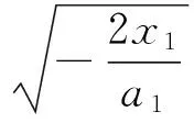
Assembling formula (2)~ (4), the velocity of piston’s reaching origin of coordinates is:
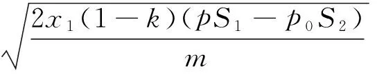
(5)
2.2.Analysisofthesecondbufferarea
As is shown in Fig.3, after reaching origin of coordinates and entering the second buffer area, hydraulic oil in it is expelled from oil-drainage outlet. Because the motion velocity is still high, pressure of high-pressure oil in buffer area keeps rising. And the impact piston’s kinetic equation is:
(6)
In the equation,phis pressure of high-pressure oil in the second buffer area (Pa).
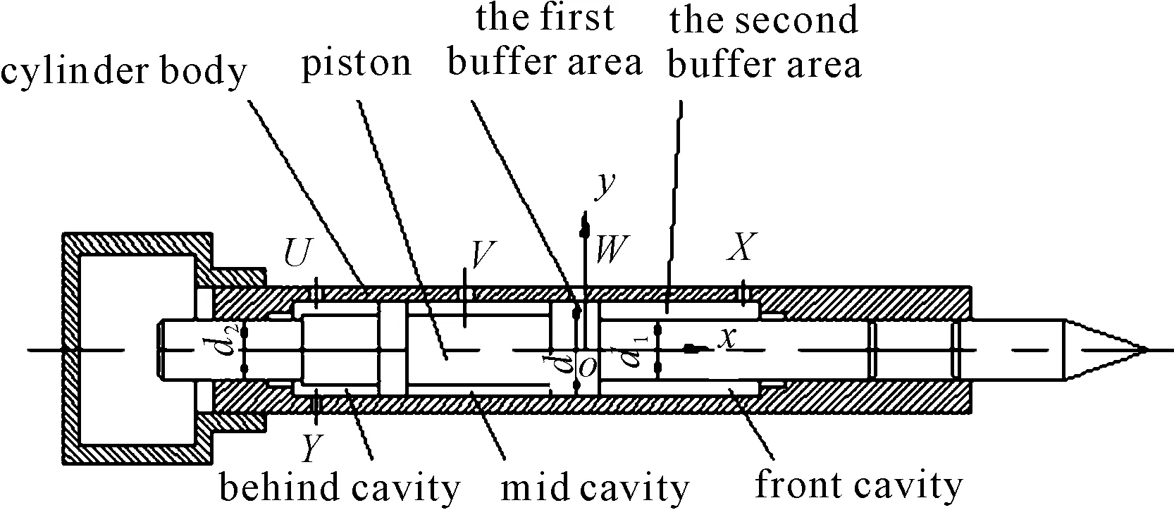
Fig.3 Structure diagram of the piston located in the second buffer area
If the influence of hydraulic oil’s condensibility and shear flow elided, according to hydromechanics theory, hydraulic oil’s leakage rate in the second buffer area is:
(7)
In the equation,dis diameter of piston’s shoulder (m),d1is piston’s front-end diameter (m),δis backlash between piston’s shoulder and cylinder body (m),δ1is backlash between piston’s front end and front supporting sheath (m),μis dynamic viscosity of hydraulic oil(Pa·s),l1is oil sealing length between piston and front supporting sheath (m),εis relative eccentricity between piston’s shoulder and inner cylinder body,ε1is relative eccentricity between piston’s front end and front supporting sheath hole.
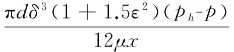
When piston rushes forward, the flow rate of hydraulic oil from buffer cavity is:

(8)

3.Conclusions
This paper introduced the operation principle of a new type of hydraulic drill machine. On the basis of uniform retarded motion and variable decelerated motion, this paper analyzes the movement of piston in buffer oil pad area, and gives the calculating method of buffer oil pad area’s length. The calculation method, that this paper presented, has applied successfully in YYT30 hydraulic drilling machine. It is valuable both in theories and the applications to solve piston’s empty hitting phenomenon.
[1] Geof Perse.Hydraulic Rock Drills[J].Mining Magazine,1985(3): 220-231.
[2] Fiscor Steve.Underground miners test new hydraulic drill[J].Engineering and Mining Journal,2004,205(9):46-47.
[3] Placido Joao R.A New Type of Hydraulic Hammer Compatible with Conventional Drilling Fluids[C]//Proceedings SPE Annual Technical Conference and Exhibition,2003:2601-2607.
[4] Eliss D,Chiang L.Dynamic analysis of impact tools by using a method based on stress wave propagation and impulse-momentum principle[J].ASME Journal of Mechanical Engineering,2003,125:131-142.
新型液压凿岩机活塞缓冲油垫区长度设计
万 圣*,谢晓利
四川工程职业技术学院,四川 德阳 618000
由于凿岩工作环境比较复杂,如岩石中有裂缝、岩石软硬不均以及操作不当等,使得凿岩机活塞不能及时撞击到钎尾,从而出现空打现象。为了避免这种现象的发生,有必要确定活塞缓冲油垫区长度。根据新型液压凿岩机活塞等减速缓冲阶段运动规律及活塞变减速缓冲阶段运动规律,分别列出了活塞动力学方程表达式,进一步导出了活塞空打时缓冲期间的运动速度和加速度运算表达式,给出了活塞缓冲油垫区长度设计计算方法。
新型液压凿岩机;冲击活塞;油垫区长度
TD421.2
2013-01-09
*WAN Sheng.E-mail:wanshengwww@163.com
10.3969/j.issn.1001-3881.2013.06.022
猜你喜欢
杂志排行
机床与液压的其它文章
- Research and Realization of the Control System for Cement Screw Packing Machine Based on MCGS and S7-200PLC
- The Analysis and Countermeasure of Centrifugal Atomizer Nozzle Block Up
- Static and Dynamic Characteristic Analysis for Vehicle MRF Damper
- Multi-physics Coupling of Hydraulic System
- Research of Production Configuration Management Based on the Internet of Things-mixed Cloud Enterprise
- Research and Design of Embedded Serial Device Server on the DNC System