Calibration and cancellation of microwave crosstalk in superconducting circuits
2023-10-11HaishengYan严海生ShoukuanZhao赵寿宽ZhongchengXiang相忠诚ZitingWang王子婷ZhaohuaYang杨钊华KaiXu许凯YeTian田野HaifengYu于海峰DongningZheng郑东宁HengFan范桁andShipingZhao赵士平
Haisheng Yan(严海生), Shoukuan Zhao(赵寿宽), Zhongcheng Xiang(相忠诚), Ziting Wang(王子婷),Zhaohua Yang(杨钊华), Kai Xu(许凯),4,†, Ye Tian(田野), Haifeng Yu(于海峰),4,Dongning Zheng(郑东宁),4,5,6, Heng Fan(范桁),4,5,6, and Shiping Zhao(赵士平),4,5,6
1Beijing National Laboratory for Condensed Matter Physics,Institute of Physics,Chinese Academy of Sciences(CAS),Beijing 100190,China
2School of Physical Sciences,University of Chinese Academy of Sciences(UCAS),Beijing 100190,China
3Beijing Academy of Quantum Information Sciences,Beijing 100193,China
4Hefei National Laboratory,Hefei 230088,China
5CAS Center for Excellence in Topological Quantum Computation,UCAS,Beijing 100190,China
6Songshan Lake Materials Laboratory,Dongguan 523808,China
Keywords: superconducting qubit,microwave crosstalk,Rabi oscillation
1.Introduction
Superconducting qubits are an excellent platform for quantum simulation and quantum computation,[1–3]which have been widely used to simulate many-body phenomena in condensed-matter physics[4–13]and demonstrate quantum advantage.[14,15]In the applications, the precise controls of qubits are required and crosstalks among different control lines need to be eliminated.Qubit controls usually utilize flux bias signals for tuning the energy level spacing(Zcontrol)and microwave signals for manipulating the quantum state (XYcontrol).With the present-day devices fabricated by the flipchip technology etc., crosstalk among theZcontrol lines can be made as small as 0.1%.[13]However, crosstalk among theXYcontrol lines remains relatively large, usually above 1%.Further eliminating the crosstalk of theXYcontrol lines, or the microwave crosstalk, is therefore important for the applications of superconducting circuits.
The microwave crosstalk signal can be eliminated in principle by cancellation with a compensation signal of the same amplitude and frequency but 180°out-of-phase.This method is used in quantum simulation experiments of dynamical phase transitions[7]and thermalization,[8]in which all superconducting qubits are biased with the same frequency.More recently,it is also applied to the superconducting circuits with different fixed-frequency qubits, using the alternative-current Stark effect to measure the Stark-induced phase for the determination of the compensation signal parameters.[16]The microwave crosstalk effect and its mitigation have also been investigated to improve the gate performance.[17,18]
In this work, we present and experimentally demonstrate a method of calibrating and cancelling the microwave crosstalk via compensation signals, in which systematic formulation and steps for obtaining the crosstalk matrix are described.Our method can be applied to superconducting circuits with frequency-tunable qubits operating with a common frequency as well as different frequencies.The crosstalk matrix can be conveniently determined for a given device with orders of magnitude difference of crosstalk strengths among different qubit control lines.We will use a superconducting 10-qubit chain device (see Fig.1) with the crosstalk strength ranging from 0.18%to 98%,(The crosstalk strength has wide variation for the present device,which partly results from the specific sample design.For instance, theXYcontrol lines of Q1and Q10locate at different qubit positions compared to those of Q2through Q9.Also, theXYcontrol lines of Q2to Q6sit at the opposite side of theZcontrol lines as compared to the cases of Q7to Q9(see Fig.1).)and demonstrate the successful calibration and cancellation of microwave crosstalk by two to three orders.The qubit chain is governed by 1D Bose–Hubbard model,which is nearly integrable when the high level states are only sparsely populated.[12,19]The model becomes nonintegrable when a microwave field is applied.[8,19,20]We will show a clear thermalization process in the nonintegrable system,demonstrating that the microwave crosstalk is globally suppressed.
2.Microwave crosstalk in superconducting circuits
To start, we present a general formulation for quantifying the microwave crosstalk in a superconducting circuit ofNqubits with different frequencies.We defineΩm(t)andΩ′m(t)as the actual microwave signal which a qubit receives and the driving signal input to theXYcontrol line of this qubit,respectively,as shown in Fig.2 in the simple case with two qubits.To determine the crosstalk matrix,one applies microwave signals to the control lines and measure the responses of the qubits.ThereforeΩ′m(t) does not contain cross-qubit terms and we write
HereΩmnandφmnare the parameters for signals applied on the mth qubit by the nth qubit drive with frequencyωn,thus those withn/=mdescribe the microwave crosstalk signals.For the matrix representation,it is convenient to rewrite Eq.(1)in the form with complex quantities:
It is clear that taking the real part of Eq.(2) goes back to Eq.(1).We further define column vectorsΩ(t) andΩ′(t)as
to have
in whichMis the crosstalk matrix defined by
withamn=Ωmn/Ωnn.We will show how to determine the matrixMbelow.With knownM, the required microwave signals input from the qubit drive lines can be calculated for the given signals actually applied on qubits for performing a specific operation in the circuit,via
HereM-1is the inverse matrix ofM.We note that after obtainingM,in contrast to the definitions in Eqs.(1)and(2),anΩ(t) without cross-qubit terms is often required for specific operations in experiment.On the other hand,Ω′(t) applied to the qubit control lines calculated from Eq.(6)will contain all terms, namely signals with different frequencies need to be applied to a given qubit control line in order to cancel the crosstalk signals from the other qubit control lines.

Fig.1.Optical micrograph of the superconducting 10-qubit chain.Each qubit has a microwave line for XY control,a flux bias line for Z control,and a readout resonator for measurement.
The physical meaning of the parameters in the above formulation can be readily seen.In the two-qubit case shown in Fig.2,the microwave signals are experimentally applied to the drive lines of qubits Q1and Q2, which, according to Eq.(1),are=Ω11cos(ω1t+φ11) and=Ω22cos(ω2t+φ22),respectively.Writing these in the form of Eq.(2),inserting them into Eq.(4), and taking the real parts, we have for Q1:
which is also given by Eq.(1).HereΩmnare the Rabi frequencies of them-th qubit by then-th qubit drive with frequencyωn.Since the matrixMhas unity diagonal elements, equation(4)says that the line attenuations are taken into account by first experimentally calibratingΩ11andΩ22for corresponding signal strength(or amplitude)applied to the control lines.Ω12andφ12in Eq.(7) can be obtained in the following way.We first setω1=ω2andφ22=0.Q1is also biased toω2while Q2is biased far away (e.g., 200 MHz or above) to be decoupled from Q1.We have
With these the Hamiltonian of Q1reads
Using the rotation wave approximation we have
in whichΔq=ωq-ω2is the qubit detuning with respect to the driving frequency, usually set to zero in experiment.The Rabi frequencyΩRof Q1is found to be
We will show experimentally that with givenΩ11,Ω22,ω1=ω2, andφ22=0, one can measure the Rabi frequencyΩRof Q1as a function ofφ11,and the parametersΩ12andφ12can be obtained by fitting the experimental data using Eq.(11).The corresponding matrix element inMis therefore determined.Note that whenφ11=φ12,ΩRreaches a maximum value,indicating that the signals arriving at Q1from the two drive lines have a common phase.In other words,φ12±2πnrepresents the phase difference resulting from the different delay times across the two drive lines.
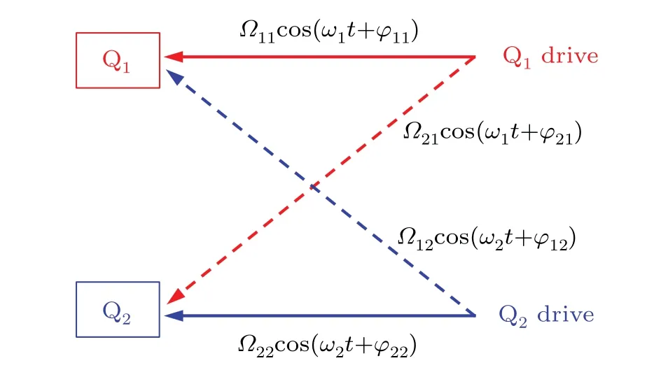
Fig.2.Schematic diagram of microwave signal crosstalk shown with two qubits as an example.Here Ωmn and φmn are the parameters for signals applied on the m-th qubit by the n-th qubit drive with frequency ωn.
To measure the Rabi frequency,we note that the rotation axisnof the Rabi oscillation in Bloch sphere is
with
The unitary operator for the state evolution becomes
whereσis the Pauli matrices.For Q1initialized in the ground state|0〉,its time evolution is
and the probabilityP1that Q1stays in the first-excited state|1〉is given by
The Rabi frequencyΩRcan be obtained by measuringP1versus timet.For Q2,the parametersΩ21andφ21can be known in the similar way, and all the matrix elements inMare then determined by the measurements between different qubit pairs.
The above formulation of the microwave crosstalk considering different superconducting qubit frequencies should be useful for multiqubit systems where qubit frequencies are much crowded so that certain qubit frequencies are not possible to set sufficiently apart for precise gate operations.[16,18]However, without loss of generality, we will experimentally demonstrate our method for the calibration and cancellation of microwave crosstalk in the superconducting 10-qubit chain with widely varied crosstalk strength in the resonant case,namely with all qubits biased at the same frequency, a situation in which numerous analog quantum simulation experiments are performed.[5–13]A photograph of the device used in the experiment is shown in Fig.1 and its basic parameters are listed in Table 1.
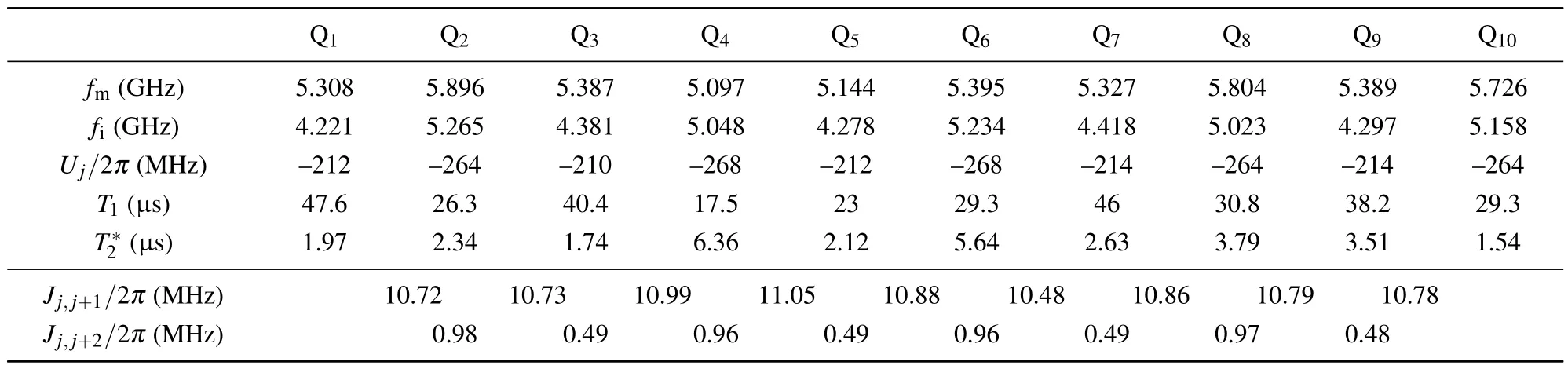
Table 1.Basic device parameters. fm and fi are the qubit maximum and idle frequencies. Uj is the qubit anharmonicity. T1 and T*2 are the energy relaxation and dephasing times of the qubit at idle point. Jj,j+1 and Jj,j+2 are the coupling strengths of nearest neighbor(NN)and next nearest neighbor(NNN)qubits.The working frequency ω0 is 4.445 GHz.
3.Experimental results and discussion
Quantum simulation experiments of thermalization in nonintegrable systems are usually performed using the quench process with an initial state evolving under suddenly changed Hamiltonian and all qubits set at a common working frequencyω0.We will useω0/2π=4.445 GHz for the simulation experiment to test the global elimination of microwave crosstalk.To demonstrate our crosstalk calibration method,we consider Q1and Q2, and determine the parametersΩ12andφ12.For this, we setΔq= 0,ω1=ω2=ω0,Ω11/2π= 10 MHz,Ω22/2π=58 MHz,andφ22=0.HereΩ22needs to be larger thanΩ11to observe a clear crosstalk effect.We then measure the time evolution ofP1as a function ofφ11.The results are shown in Fig.3(a)with the extracted Rabi frequency versusφ11plotted in panel (b) with symbols (further improved results are shown in Fig.4, as discussed below).Fitting the experimental data in Fig.3(b)with Eq.(11),shown as a solid line,we obtainΩ12/2π=56.97 MHz andφ12=1.8377,leading toa12=98.22%.Hereφ12is equal toφ11with maximum Rabi frequency,as can be seen in Eq.(11).Likewise for the measurement ofΩ21andφ21, we setΩ11/2π=58 MHz,Ω22/2π=10 MHz,andφ11=0,and measure the time evolution ofP1as a function ofφ22.Repeating the above procedure,we obtainΩ21/2π=4.095 MHz andφ21=-1.808, leading toa21=7.06%.

Fig.3.(a)Experimental time dependence of P1 as a function of φ11 for Q1 at the first stage for the measurement of M1. Ω11/2π =10 MHz,Ω22/2π =58 MHz, and φ22 =0 are used for the microwave signals input to the qubit control lines.(b)Rabi frequency versus φ11 extracted from the data in panel(a)(symbols).The solid line is a fit with Eq.(11),from which we obtain Ω12/2π =56.97 MHz and φ12 =1.8377, giving rise to a12 =98.22%.An upward arrow indicates the point where φ12=φ11 with maximum Rabi frequency.
The obtained crosstalk matrix elements between Q1and Q2are illustrated in Fig.5(a).We see that the matrix elementa12is nearly 100%,meaning that when we apply a microwave signal to Q2, a signal of nearly the same amplitude will also be applied to Q1.Unlike the superconducting device with allto-all qubit connection,[7]a strongly varied crosstalk strength is expected for the present chain-like device due to the special sample configuration.For such device,multiple crosstalk calibration and cancellation steps are required.In practice,with knownMwe can use Eq.(6)to calculate the microwave signalsΩ′(t) that need to be applied to the control lines for the actual signalsΩ(t) required on the qubits.To test how accurately the calibration can be achieved, we consider Q1and Q2and experimentally setΩ′(t)withΩ11/2π=10 MHz,Ω22/2π=58 MHz,φ22=0, and check Rabi oscillations of Q1versusφ11again.However, these signals are transformed byM-1before applied to the qubit control lines (note thatMis a 2×2 matrix at the moment).Let us useM1to denoteMobtained above.Due to the experimental errors of various kinds and large crosstalk near 100% and quantum crosstalk resulting fromZZinteraction[21,22]in the system,M1may not accurately describe the microwave crosstalk of the system.If a matrixM=M2M1better describes the microwave crosstalk,we haveΩ(t)=M2M1Ω′(t).The transformation bymeans experimentally settingΩ′(t)→Ω′(t),and we haveΩ(t)=M2Ω′(t).The matrixM2in this case is expected to be close to a unit matrix with off-diagonal elements close to zero.
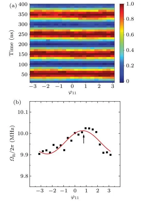
Fig.4.(a)Experimental time dependence of P1 as a function of φ11 for Q1 at the fourth stage for the measurement of M4. Ω11/2π=10 MHz,Ω22/2π =58 MHz, and φ22 =0 are used for the microwave signals input to the qubit control lines.(b)Rabi frequency versus φ11 extracted from the data in panel(a)(symbols).The solid line is a fit with Eq.(11),from which we obtain Ω12/2π =0.0573 MHz and φ12 =0.6876, giving rise to a12 =0.099%.An upward arrow indicates the point where φ12=φ11 with maximum Rabi frequency.
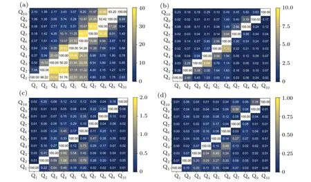
Fig.5.Microwave crosstalk calibration matrices of(a)M1,(b)M2,(c)M3,and(d)M4 obtained at four successive stages,in which the color bars represent the matrix element values up to 40%,10%,2%,and 1%,respectively.The data above these values are illustrated in black and white.The average values of off-diagonal matrix elements for M1,M2,M3,and M4 are 13.50%,0.7415%,0.1823%,and 0.0808%,respectively.
The similar measurements of Rabi oscillations of Q1versusφ11and of Q2versusφ22result in the parameters ofΩ12/2π=1.443 MHz,φ12=1.706,Ω21/2π=0.1494 MHz,andφ21= 1.130 forM2, giving rise toa12= 2.49% anda21=0.26%,which are illustrated in Fig.5(b).M2obtained at this second stage provides a proper estimate of how preciseM1calibrates the microwave crosstalk of the system.Similarly, we can writeM=···Mi···M1withMicloser to unit matrix for largeri.Figures 5(c)and 5(d)illustrate the results forM3andM4,respectively.At each calibration stage,M=···Mi···M1is calculated in the 10×10 matrix form(see below) and the 2×2 matrices are taken from the results to obtain the 2×2 inverse matrices for input signal transformation.Experimental results of Rabi oscillations of Q1corresponding to the data in Fig.3 and producing the matrix elements ofM4at the fourth stage are presented in Fig.4.We can see a much smaller variation amplitude of the Rabi oscillation withφ11due to a much reducedΩ12[see Eq.(11)],which leads to a much reduceda12.
The above microwave crosstalk calibration method used between Q1and Q2are applied to other qubit pairs in the 10-qubit chain.The results ofM1throughM4are presented in Fig.5.It can be seen that at the second calibration stage,namely withM=M2M1, the crosstalk among the qubits are already well below 1%, which can be seen and estimated fromM3in Fig.5.The average values of off-diagonal matrix elements forM1,M2,M3, andM4are 13.50%, 0.7415%,0.1823%,and 0.0808%,respectively.
To further test the effectiveness of the calibration,we consider the 10-qubit chain driven by a continuous microwave field.In the rotating frame with a common qubit frequency,the system is governed by the 1D Bose–Hubbard model in a transverse field[4,6,20]reads
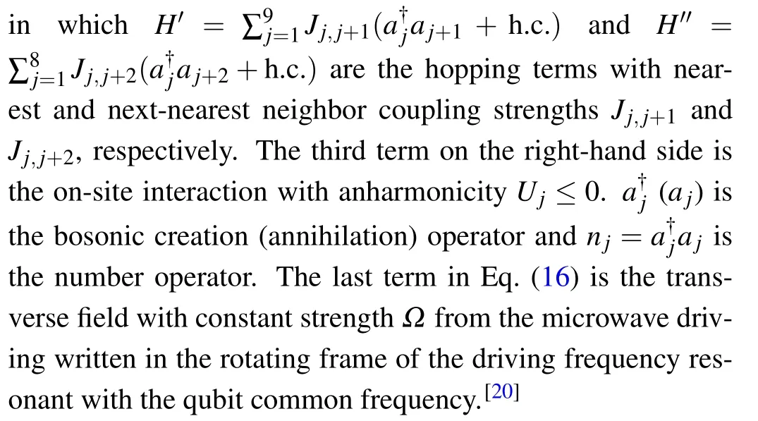
Equation (16) well describes the 10-qubit chain driven under a continuous microwave field.The sample parametersUj,Jj,j+1,andJj,j+2are listed in Table 1.In Fig.6,we show the experimental (symbols) and calculated (lines) time evolutions of the local observables〈σz〉0=(1/5)∑oddj〈σzj〉 and〈σz〉1=(1/5)∑evenj〈σzj〉 starting from the Néel initial state|0101010101〉 (lines).[20]Here〈σzj〉 is the expectation value ofσzjofj-th qubit.Experimentally,the Néel state is prepared with the qubits biased at their respective idle frequencies listed in Table 1 via theZcontrol lines.Then the microwave field is applied via theXYcontrol lines with the qubits set at the common frequencyω0for state evolution and the observablesσzjis measured for each qubit at different evolving times.Figure 6(a)shows the results forΩ/2π=0,with which the system is near integrable.The expected fluctuating behaviour of the observables during the evolution can be clearly seen with good agreement between experiment and theory.The calculated results withΩ/2π=5 MHz,where the system becomes nonintegrable,are plotted as lines in Figs.6(b)and 6(c).Both〈σz〉0and〈σz〉1exhibit a fast thermalization behaviour,[8,19,20]quickly decreasing and increasing to zero from +1 and-1,respectively.Experimental results in Fig.6(b) are measured without microwave calibration showing clear deviations between experiment and theory,while those in Fig.6(c)with the calibration usingM=M3M2M1crosstalk matrix(see Fig.5 forM1,M2,andM3).Excellent agreements between the experimental and theoretical data Fig.6(c)confirm the effectiveness and accuracy of our crosstalk calibration and cancellation method.

Fig.6.Time evolutions of local observables 〈σz〉0 =(1/5)∑oddj〈〉and〈σz〉1=(1/5)∑evenj〈from the Néel initial state|0101010101〉under the Hamiltonian Eq.(16).(a) Ω/2π =0 MHz, showing a fluctuating behaviour of the observables in near integrable system.(b)Ω/2π =5 MHz,suggesting thermalization of nonintegrable system in microwave field without calibration.(c)Ω/2π =5 MHz, demonstrating a fast thermalization process of nonintegrable system in calibrated microwave field,with good agreement between experiment and theory.
In the previous experiment,[7]the crosstalk matrix elements are measured in two steps.Let us consider Q1and Q2again.Also after the calibrations ofΩ11andΩ22,Ω12is first determined by settingΩ11=0 and applyingΩ22withφ22=0.In the second step,Ω11=Ω12is used.Thenφ12is found by measuring the Rabi frequency againstφ22withφ11=0.The present experiment combines the two steps into one.Since we have setΩ11/2π=10 MHz in the calibration, from Eq.(11)we always have the Rabi frequency above 10 MHz, corresponding to an oscillation period below 100 ns,which is convenient for the measurement.In practice, we find the present method convenient and efficient especially for calibrating and cancelling the microwave crosstalk with large amplitudes and wide variations such as those in the 10-qubit chain device.Using repeated measurements ofMiinM=···Mi···M1, we can successively improve the accuracy of the calibration and cancellation of the microwave crosstalk.
As a final remark,we emphasize that our method for the microwave crosstalk calibration can be applied to the case with different qubit frequencies though the calibrations discussed so far are performed with a common qubit frequency for the quantum quench experiment.In the cases with different qubit frequencies,the calibration for each qubit pair can be done in exactly the same way.Generally, the amplitude and phase of the crosstalk matrix elements are frequency-dependent,as can be seen in Fig.7 for Q1and Q2measured in the frequency range between 4.445 GHz and 4.695 GHz.Therefore, the crosstalk calibration of a given qubit pair needs to be done again when their working frequencies change.

Fig.7.Measured frequency dependences of the amplitude(a)and phase(b)of the microwave crosstalk matrix elements for Q1 and Q2.
4.Summary
We have presented a method for the calibration and cancellation of microwave crosstalk in superconducting circuits.Starting from a general formulation of the problem, in which the crosstalk matrix was defined and the matrix elements could be found from the qubit Rabi oscillations,we proceeded to experimentally demonstrate the calibration and cancellation of microwave crosstalk and its effectiveness in a superconducting 10-qubit chain.We showed that a matrix element could be determined in a single step by measuring the Rabi frequency of a given qubit as a function of the phase of the signal applied to this qubit control line, while another signal was applied to the control line of the crosstalking qubit.We found that the method was convenient and efficient especially for calibrating and cancelling the microwave crosstalk with large amplitudes and extensive variations like those in the 10-qubit chain device studied in this work.The calibration and cancellation could be performed successively to reduce the microwave crosstalk effectively by two to three orders.We further tested the method by the observation of the thermalization phenomena in the nonintegrable system with excellent agreement between experiment and theory.
Acknowledgements
Project supported by the Key-Area Research and Development Program of Guangdong Province, China (Grant No.2018B030326001) and the National Natural Science Foundation of China(Grant No.11874063).H F Yu acknowledges supports from the Natural Science Foundation of Beijing (Grant No.Z190012) and the National Natural Science Foundation of China(Grant No.11890704).H Fan acknowledges supports from the National Natural Science Foundation of China(Grant Nos.11934018 and T2121001),Strategic Priority Research Program of the Chinese Academy of Sciences (Grant No.XDB28000000), and Beijing Natural Science Foundation(Grant No.Z200009).
猜你喜欢
杂志排行

Chinese Physics B的其它文章
- Dynamic responses of an energy harvesting system based on piezoelectric and electromagnetic mechanisms under colored noise
- Intervention against information diffusion in static and temporal coupling networks
- Turing pattern selection for a plant–wrack model with cross-diffusion
- Quantum correlation enhanced bound of the information exclusion principle
- Floquet dynamical quantum phase transitions in transverse XY spin chains under periodic kickings
- Generalized uncertainty principle from long-range kernel effects:The case of the Hawking black hole temperature