Data-Centric Approach to Digital Twin Modeling of Production Lines
2023-09-22DINGYongxiao丁永效LIJiqi李纪奇LIUGuohua刘国华NIPingWUJinfa吴金发
DING Yongxiao(丁永效), LI Jiqi(李纪奇), LIU Guohua(刘国华)*, NI Ping(倪 萍), WU Jinfa (吴金发)
1 College of Computer Science and Technology, Donghua University, Shanghai 201620, China 2 College of Mechanical Engineering, Donghua University, Shanghai 201620, China
Abstract:Digital twin (DT) is a virtual replica of a physical world that has become one of the most important ideas in the manufacturing industry’s digital revolution. DT modeling is a vital issue in building a DT of a production line. In this paper, a method is proposed to address the difficulties of complicated production line business and data heterogeneity. The method focuses on essential data in the production line and creates conceptual and information models based on the ArtiFlow model and AutomationML (AML). Conceptual models are mainly used to describe and analyze the business activities of the production line, and information models describe real production lines in the form of XML files. The proposed modeling approach has been applied to a real-world clothing production line to demonstrate its feasibility and effectiveness.
Key words:digital twin(DT); ArtiFlow; production line; AutomationML(AML)
0 Introduction
The manufacturing industry is the backbone of a country’s economy and a key measure of its overall national strength[1]. All countries in the world regard the development of intelligent manufacturing as a critical measure for their own countries to gain a competitive advantage in the manufacturing industry. With increased market competitiveness and the rapid development of a new generation of information technology, the digital twin (DT) has emerged as one of the essential topics for achieving intelligent manufacturing[2]. DT is described as making full advantage of the physical model, sensor update, operating history and so on. The simulation method of multi-discipline, multiple physical quantities, multi-scale and multi-probability is merged to complete the mapping in a virtual environment, so as to portray the full life cycle process of the related entity equipment[3]. DT can help managers in manufacturing to fully control the critical information on the production line, optimize resource allocation, and improve production efficiency[4].
The DT concept was originated by Grieves in 2002 to create a virtual replica of a physical entity[5]. National Aeronautics and Space Administration (NASA) described a spacecraft DT[6]and the U.S. Air Force Research Laboratory (AFRL) used DTs to solve the maintenance problem of fighter airframes. Grieves published a white paper on DTs[5]. Taoetal.[7]proposed the concept of shop-floor DT, which attracted significant attention from researchers. Subsequently, DT has been widely studied and applied in manufacturing[3, 8-10]. Modeling is the first step in building a DT system. The 3D model proposed by Grieves[5]and the five-dimensional model perfected by Taoetal.[7]laid a theoretical foundation for DT modeling. The DT five-dimensional model includes physical entities, virtual models, DT services, twin data, and interactive connections of components.
On this basis, scholars have proposed many modeling ideas from different angles[11-14]. Zhuangetal.[15]believed that DT modeling on the shop floor should focus on five dimensions:geometry, physics, behavior, rules, and data. The DT of the shop floor can be effectively constructed by modeling these five dimensions. Liuetal.[16]proposed the concept of cyber-physical system nodes (CPSNs) and introduced an easy-to-deploy DT construction framework based on CPSNs. The CPSN includes a semantic information models, geometric models, and functional modules. Jiangetal.[17]proposed a virtual modeling method based on discrete event system modeling theory. This method can efficiently create a DT model during the design phase of a manufacturing system. Baoetal.[18-19]proposed the modeling methods of product DT, process DT and operation DT.
Although existing research has promoted the application of DT in manufacturing, it is not enough to address some challenges in the DT modeling of production lines. (1) The current use of DT in production lines is still in its early stages, and specific modeling methodologies are lacking. (2) The production line contains various elements and complex business processes, and it is not easy to fully represent the entire production process in the design stage.
This paper presents a data-centric DT modeling method for production lines to solve the above problems. The method initially examines the components of the actual production line and extracts the important data entities. Then, we create a conceptual model of the production line with ArtiFlow. Finally, the information model of the production line is developed based on AutomationML (AML). A DT of a production line can be built by analyzing the information model. The proposed method is applied to a real-world garment production line.
1 Proposed Method
The method can be divided into three steps:analyzing the physical production line and extracting data entities; building a conceptual model centered on key data entities; using AML to describe the conceptual model as an information model. The DT modeling framework of the production line is illustrated in Fig.1.
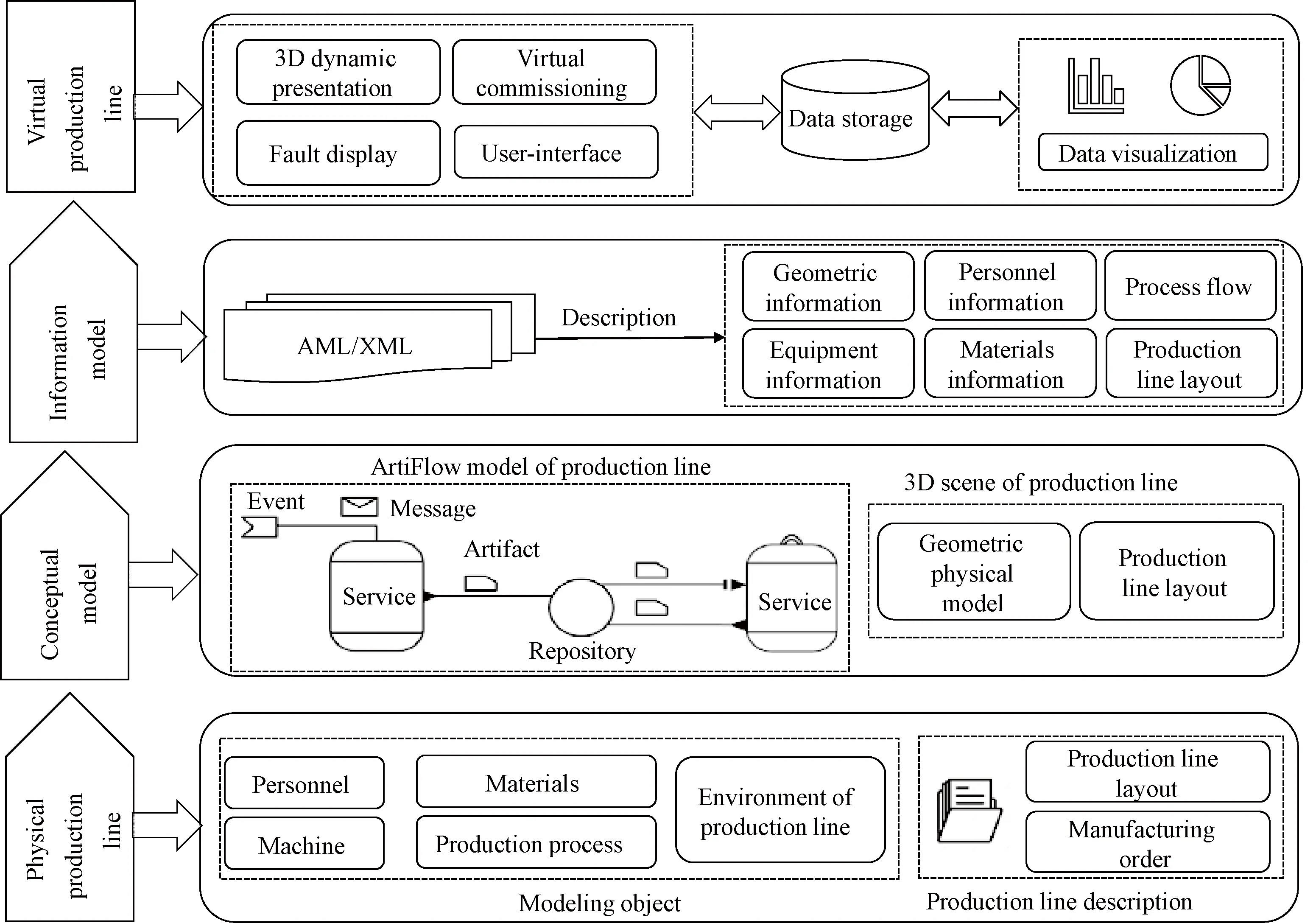
Fig.1 Digital twin modeling framework of production line
Step1Analyze the physical production line and extract data entities
It is required to examine the modeling objects involved in the production line to develop a DT of a production line. The modeling objects of the production line include elements and production process. The production elements include personnel, machines, materials, and environment of the production line, and the production process consists of a series of technological processes. The above elements of production are all data entities. Developers can use entity-relationship diagrams to describe the information model of data entities.
Step2Build a conceptual model of the production line
The conceptual model of the production line includes the ArtiFlow model of the production line and the 3D scene of the production line. The ArtiFlow model starts from an artifact and uses a variety of graphical elements to comprehensively and intuitively describe the production activities of the production line. The 3D scene of the production line visually displays the production process of the production line in the form of 3D animation.
Step3Build the information model of the production line based on AML
The production line contains various elements and production processes and has complex topology and data heterogeneity. These characteristics make it difficult for data to interact between different modules. Therefore, a unified information model must be established to describe the production line. A production line information model is a digital description file of a production line, which is typically described based on AML. The information model records the 3D geometry, personnel, process flow, equipment, materials, and production line layout. By analyzing the information model, the critical data for building the DT system of the production line can be obtained.
The DT application of the production line can be built by these three steps. Since step 1 is easy to accomplish, the implementation details are introduced from step 2.
2 Construction Method of Conceptual Model of Production Line
According to Fig.1, the conceptual model of the production line includes the ArtiFlow model and the 3D scene of the production line. The following sections describe in detail how these two parts are constructed.
2.1 ArtiFlow model of production line
An artifact is the carrier of critical data in the business process, saving data and life cycle information related to completing business goals. The artifact-centric process design method proposed by International Business Machines Corporation(IBM) has been applied to many fields such as finance, insurance, and medicine[20]. Subsequently, Liuetal.[21]proposed ArtiFlow, an artifact-oriented business process description model. ArtiFlow uses a variety of graphic elements to describe business processes abstractly. ArtiFlow models can accurately describe the production process and provide the basis for analysis, optimization, and implementation. The artifact-centric modeling approach combines data with processes, emphasizing the importance of key data in the modeling process. Figure 2 gives a graphical representation of the essential elements in the ArtiFlow model.

Fig.2 Graphical representation of ArtiFlow model’s essential elements
ArtiFlow model contains service elements, repository elements, artifact elements, transmission pipeline elements, message and event elements[22]. One or more operations in a production process that accomplish a specific task are abstracted as service elements. Service elements are divided into triggerable services and non-triggerable services. Triggerable services need to be triggered by production events, while non-triggerable services generally run automatically and do not require event triggering. Repository elements temporarily store artifacts in the production process. The interaction between the service and repository elements relies on the transmission pipeline element. There are three types of transmission pipeline elements:read-only, write-only, and conditional read. The service element can perform update operations on the artifact through the transmission pipeline.
Establishing an ArtiFlow model for the production line has two advantages. (1) The managers can use the graphical elements of ArtiFlow to communicate intuitively and comprehensively in the design stage of the production line. (2) The workshop manager can fully and effectively control the critical data of the production line and data life cycle, timely estimate production bottlenecks, thereby improving the production efficiency of the production line.
2.2 Construction steps of ArtiFlow model
An ArtiFlow model is a six-tuple (N,Γ,S,R,C,Ru)[23]. Among them,Nis the name of the ArtiFlow model;Γis an ArtiFlow pattern, including a set of all artifact types;Sis a finite set of service elements;Ris a finite set of repository elements;Cis a finite set of transmission pipelines;Ruis a finite set of production rules.
According to step 1 in section 1, the manufacturing order is the artifact that affects the production line. The following steps are required to construct the ArtiFlow model of the production line.
1) Construct the ArtiFlow patternΓ.
Analyze production business activities to uncover all artifacts.
2) Traverse the setΓand construct the macro level life cycle of each artifact.
The macro life cycle in an artifact in the production process is the key stage in producing. In this step, developers can use flowcharts to describe the life cycle of the artifact.
3) Define the service element setS, the repository element setRu, and the transmission pipeline element setCin the ArtiFlow model.
Traverse the setΓ, and define related service elements, repository elements, and transmission pipeline elements according to the macro life cycle of each artifact. Service elements include name, trigger conditions, execution rules, and possible events. At the same time, the artifact should be temporarily stored in the repository element after being operated by the service element. The service elements and repository elements are connected through different transmission pipeline elements. The service elements, repository elements, and transmission pipeline elements generated in this step are stored in setsS,R, andC, respectively.
4) Draw the ArtiFlow model diagram of the production line.
The developer can iterate through all the above sets and map each element in the sets to the graph in Fig.2.
2.3 Building of a 3D scene of a production line
The 3D scene of the production line can be constructed by the layout drawing and the geometric model of the production line. According to the analysis of step 1 in section 1, it can be obtained that the general production line includes five basic production factors, including personnel, machines, materials, production processes, and environment. 3D models of the production line may be built using 3D geometric modeling software, which translates models into FBX format. PiXYZ software is used to lighten the geometric model of the production line to reduce the occupation of system memory as much as possible. A 3D scene of the production line can be constructed using the geometric model of the production line and Unity software.
3 Construction of Production Line Information Model Based on AML
AML is an open, neutral XML-based data exchange format used to support data exchange between various engineering tools. AML can store and exchange data, including plant topology information, geometric kinematics, and logic information[24]. Figure 3 shows the basic structure of AML.

Fig.3 Basic structure of AML
AML provides four concepts[25], including InstanceHierarchy, RoleClass, SystemUnitClass and InterfaceClass. InstanceHierarchy defines the topology of the production line. RoleClass adds semantic information to production resources. SystemUnitClass allows the storage of user-defined AML classes. InterfaceClass serves for the description of relations between objects.
4 Case Study
Garment production is an organized activity consisting of sequential processes such as laying, marking, cutting, stitching, checking, finishing, pressing and packaging[26]. The primary research of this paper focuses on five steps:the creation of the production plan, cutting, sewing, ironing, and packaging.
4.1 Identifying artifacts for garment production lines
A garment production line includes personnel, machines (sewing machines, ironing machines, cutting beds, conveyor belts,etc.), materials (fabrics, buttons, sewing needles,etc.), production processes, and production environments.
A garment manufacturing order (MO) is a production plan written according to the processing technology, surface accessories requirements, and order information[26]. It can assist the supervisor in assigning tasks and controlling production progress. Therefore, the MO is an artifact. Starting from the macro life cycle of artifact MO, developers can discover artifacts such as craft sheet (CS), staff list (SL), and machine list (ML).
4.2 Construction of a conceptual model of a garment production line
The garment MO includes several attributes such as contract number, style, color, size, process number, and production stage. The production stage describes the macro-level life cycle information of the garment MO. Attribute values in the production stage include ready to cut (RC), ready to sew (RS), ready to iron (RI), ready to pack (RP), and ready to delivery (RD). According to the method in section 2.2, the ArtiFlow model of the garment production line shown in Fig.4 can be constructed.

Fig.4 ArtiFlow model of a garment production line
The arrival of an order is represented as an event E, which carries a message denoted as M. The content of the message includes the detailed data of the order. The garment production process is triggered by the event E. Specifically, the handler for the event E invokes a service identified as “Create MO”. The service creates a new MO artifact instance, packs the order information into the artifact, and finally stores the new artifact in the repository RC. After the service identified as “Cutting” gets the artifacts MO, SL, and ML from different repositories, it starts executing the cutting task and generates a new MO artifact instance. The updated artifact MO of this service is stored in the repository RS. The services “Sewing” and “Ironing” update the artifact MO and store the new MO artifact instance in the repository RI and RP, respectively. After executing the last service (Package), the generated new artifact MO instance will be stored in the repository RD. In Fig.4, the macro life cycle information of the artifact MO can be clearly observed.
The garment production line studied in this paper mainly adopts the bundling layout of the rotary conveyor belt, which significantly saves the auxiliary time of material operation. The 3D scene of the garment production line constructed according to the method in subsection 2.3 is shown in Fig.5.
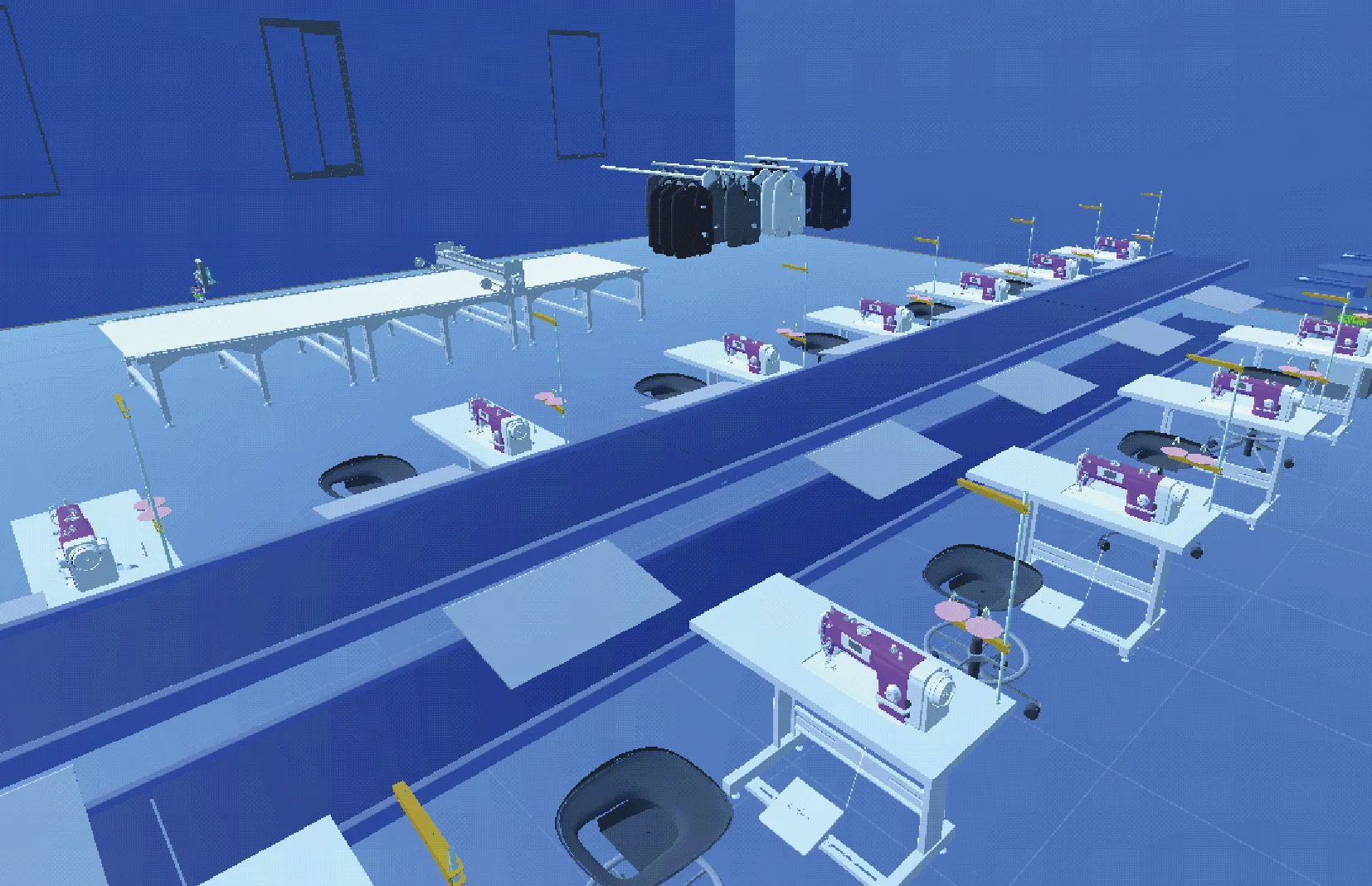
Fig.5 3D scene of garment production line
4.3 Construction of information model of a garment production line
The garment production line has 14 sewing machines, three conveyor belts, one intelligent cutting machine, and other equipment. In AML, the information model of a garment production line consists of a hierarchy of instances describing the layout of the garment production line and ArtiFlow describing the garment production process. The information model of the garment production line established using AML Editor software is shown in Fig.6. Machines have attributes such as machine number, machine type, status, location number, and description. The production line ArtiFlow is described by XML files, and AML references the XML files that describe ArtiFlow externally through the ExternalDataConnector interface. By parsing the obtained AML file, developers can obtain essential information about the garment production line.
By parsing the AML code file, a virtual production line for garment can be constructed. The virtual production line realizes functions such as 3D dynamic demonstration, virtual debugging of the production line, fault display, and data visualization. The 3D scene of the garment production line is rendered by Unity3D software and combined with the Unity Graphical User Interface (UGUI) to control the switching of viewing angles. The operation of the garment production line can be monitored from different viewpoints. Data visualization is mainly implemented by using the Vue.js framework. Through the interface, managers can view data such as fault information, the utilization rate of crucial equipment, and the motion parameters of the equipment.
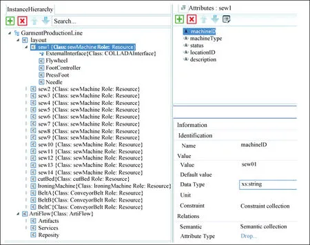
Fig.6 Information model of garment production line
As shown in Fig.7, the virtual garment production line displays critical production information in the form of 2D charts. It uses 3D animation to comprehensively and intuitively monitor the overall operation of the garment production line.
5 Conclusions
A method for modeling DTs of production lines is proposed. The approach centers on the vital data entities of the production line, emphasizing the importance of production data in the modeling process. This paper analyzes the components of the production line, extracts key data entities, and then starts from the macro life cycle of key data to build a conceptual model of the production line. The conceptual model is mainly used to describe and analyze the production business process, which can help the production line manager optimize the allocation of production resources in advance in the design stage of the production line. An information model based on AML is introduced to solve the problem of data heterogeneity in the production line. A DT of the production line can be built by parsing the information model.
The proposed modeling method is successfully applied to the garment production line, which can realize the construction of the DT system of the garment production line. Future research efforts will attempt to use real-time data to predict the production performance of equipment.
猜你喜欢
杂志排行

Journal of Donghua University(English Edition)的其它文章
- Image Retrieval with Text Manipulation by Local Feature Modification
- Multi-style Chord Music Generation Based on Artificial Neural Network
- Polypyrrole-Coated Zein/Epoxy Ultrafine Fiber Mats for Electromagnetic Interference Shielding
- Design of Rehabilitation Training Device for Finger-Tapping Movement Based on Trajectory Extraction Experiment
- High-Efficiency Rectifier for Wireless Energy Harvesting Based on Double Branch Structure
- Review on Development of Pressure Injury Prevention Fabric