Design of the Control Circuit of C523 Vertical Lathe on PLC
2014-09-14CUIXiumin
CUI Xiumin
(Shenyang Ligong University,Shenyang 110159,China)
Design of the Control Circuit of C523 Vertical Lathe on PLC
CUI Xiumin
(Shenyang Ligong University,Shenyang 110159,China)
C523 vertical lathe control circuit uses a relay control method,which has some disadvantages including large size,complex wiring,high failure rate,and maintenance difficulties.To solve these problems,a C523 vertical lathe control circuit based on PLC is designed.The electronic requirements of the control circuits,basis of PLC selection,the hardware connection and software design are described.It has been found that the PLC control circuit is simple,reliable and can highly improve the production efficiency.
PLC;vertical lathe;control program
C523 vertical lathe has a rather large size,and its control circuit is more complicated than that of the general lathe,using relay logic control method.This traditional relay control system requires a large number of intermediate relays,time relays,switches and other electrical components.Besides,to achieve interlock and linkage often needs several relays to control,taking up much space.The relays,moreover,are to be connected by wires,whose contact lines and the connection terminals are very dense.Also,the time delay of the time relay is often not very accurate,making the timing difficult.All these increase the probability of failure,and add difficulties to maintenance.And after some years of using,the electrical control system will become aged,the relay malfunctions appear frequently.The PLC is a good solution to transform the traditional relay control circuit.PLC is a product adapting computer technology to the field of industrial control.It has become one of the main pillars of modern industrial automation technology;it combines many advantages including high reliability,strong anti-interference ability,generality,and simple to program,easy t se,strong function,small size and low power consumption.Therefore,here we this Omron CP1H type PLC to re-design the electronic control system.
1 THE ELECTRICAL CONTROL REQUIREMENTS OF C523 VERTICAL LATHE
C523 vertical lathe is dragged by six sets of three-phase asynchronous motors,powered by a 380,50Hz power supply.The control circuit is powered by the step-down transformer TC 380V/27V show in figure 1.W1 is the pump motor.When the lubrication indicator on the panel lights up,show in figure 2,the spindle motor has changed form the original.
Y-Δ start to variable-frequency start.Spindle motor requires forward/reversal rotation.W2 is crossbeam elevator,W3 is crossbeam clamp motor,W4 is left vertical high-speed motor,W5 is right vertical high-speed motor,and W6 is the side motor.

Figure 1 Control system circuit

Figure 2 Control panel diagram
2 RECONSTRUCTION OF C523 VERTICAL LATHE ELECTRICAL CONTROL PLC
According to the working process of C523 vertical lathe and the electrical parameters of the existing relay control,we considered to take all the buttons,limit switches,change-over switches and other components as input elements of the PLC,and all contactor coil load as the output control object of the PLC.When connecting PLC output port,there was a total of 63 input and output points,so CPM2AH-60CDF-A programmable controller was chosen for reconstruction,having fewer load power types.First,ensure that the original control function remain the same,try to retain the original electrical components,do not add new elements,keep the main circuit and the transformer unchanged,all buttons and limit switches are connected to normally open contacts,thermal relays are connected to normally closed contacts;PLC power supply voltage is AC220V,electromagnetic clutch and brake power is DC 24V,the output port using the relay output.
During reconstruction,the main measures adopted were as followed:
1)All the original circuit relays were replaced by auxiliary relays of the PLC,greatly reducing the number of loads,thus simplify the line.
2)The power-delay time relays were replaced by PLC logic element timers,power-off delay time relays were achieved by using power-off pulse trigger mode and a certain algorithm,making the reliability of the system greatly improved.
3)Those output components,having interlock relationships on the hardware,were interlocked at the circuit output port connection to avoid causing a short circuit while energized.Although other electromagnetic clutches also had contrary motion transmissions,but even being energized simultaneously,the device wouldn′t be damaged in a short time,so no interlock was needed.
4)An electromagnetic clutch is a typical mutual inductance load.Its power is huge(relative to other relay elements),and it is likely to cause great impact on the output port,affecting the life of the PLC.Therefore the PLC is not directly connected to the output port.Instead,it is controlled via an intermediate relay.That is,the intermediate relay is controlled by the PLC in accordance with the control logic.When the relay coil is energized,the contactor turns on an action,closes the electromagnet circuit.24V power supply for the electromagnet directly,with no need of the output port of the PLC.The PLC electric ports are shown in Figure 3.

Figure 3 PLC Control Schematic
3 PLC CONTROL SYSTEM ANALYSIS OF C523 VERTICAL LATHE
C523 vertical lathe control system uses digital inputs and outputs,which can be met by a general relay output type.Here are choosing CPM2AH-60CDF-A,whose input and output points have a 20%reserved amount.
CPM2AH-60CDF-A with the overall structure,compact and fully functional,dramatically improves the space utilization.Although it a miniature type,its speed and processing capability have been much higher than the common miniature PLC,and therefore have obvious performance advantages.Its basic processing time per instruction is only 0.1μs.In order shorten the cycle time,you can use“change the unexecuted task to standby”or“will not perform the procedure area jump into the JMP-JME instruction”approach.CPM2AH-60CDF-A is equipped with two serial communication interfaces(RS-232C and RS-485),making it easy to communicate with the computer when connect to PT,various components(inverter,thermostats and smart sensors,etc.),and other PLC at the same time.
4 HARDWARE DESIGN OF THE CONTROL SYSTEM
According to the original lathe operating habits,the operating panel shown in Figure 2 will still be installed on the lift-type pushbutton station to achieve centralized control of the lathe.The control cabinet is installed in the box behind the column.Press the start button,when the control lubrication indicator lights up,press the frequency conversion start button.If operating normally,the inverter running will light up;press the frequency conversion start button.If operating normally,the inverter running will light up,and frequency display window will show the current frequency.Select the appropriate button,according to requirements of certain work piece.
5 WORK TABLE MOTOR CONTROL
Work table has four operation modes:forward,reverse,punctuality,anti point.Press the “start pump” button in Figure 2,and the corresponding input contact 0.00 is ON in Figure 3,the auxiliary relay 16.00 is switched on.When indicator light of lubrication in Figure 2 is on,Press the start button of “start frequency conversion”,and the frequency conversion input contact 0.03 in Figure 4 is on,the output coil 100.07 is on,the motor W1 works.
Contact 0.04 is the forward inching input,0.05 is the backward inching input,0.06 is the forward input,and 0.07 is the converse input.Press the corresponding button on the control panel in fig 2 to start work.Forward and converse circuits are interlocked.
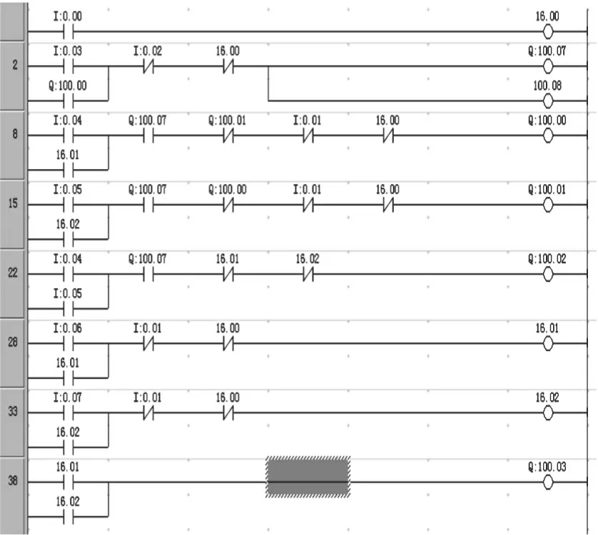
Figure 4 Work table ladder

Figure 5 Beam lifting ladder

Figure 6 Tool heads ladder
6 BEAM LIFTING CONTROL
When the beam lifting button is pressed,input contact 0.01 is on,as is shown in fig 5,auxiliary relay coil 16.01 is on,making the beam free relay coil 100.02 on.The beam is free from the clamp system,in preparation of beam lifting.Because the beam free travel switch is pressed,contact 0.03 is on,coil 100.0 is on,and the motor W2 turns forward.The beam is lifted through transmission mechanism.When the beam reaches the upper limit travel switch,contact 0.04 is off,coil 100.00 is off,and the motor W2 stops.At this time,because the upper limit travel switch is still pressed,contact 0.03 is on,coil 100.03 is on,and the motor W2 turns inversely.The beam is fastened at certain location through transmission mechanism.
If button 0.02 is pressed,the beam will going down,the whole process is similar to the beam lifting.The ladder diagram is showed in Fig.4.Its working control logic can meet the requirement.
7 TOOL HEAD MOTOR CONTROL
Tool heads includes left,right,and side head.Their motion adjustments are droved by motor W4,W5 and W6 respectively.Their motions are transmitted by connecting electromagnet with different electromagnetic clutches.Transmission mechanisms of different directions close,achieving motion transmissions of up and down,left and right.In the transformation process,the time relay KT is replaced by the PLC logic elements T(timer),and the direction control relay is replaced by auxiliary relay,greatly reducing the output points.The specific ladder diagram is shown in Figure 6.Take the left turret for an example to explain the working process.
To move the vertical turret up,turn on 0.03.Coil 16.01 is on,coil 100.05 is on,and the vertical turret moves up.To move the vertical turret quickly,turn on 0.05.Coil 100.03 is on,and the vertical turret moves quickly.When the vertical turret stops working,start timing.After 10 seconds,the control circuit breaks completely.When the turret is working,it will produce a huge mount of energy.To expand the life of the lathe,use timer to release the energy in the lathe.The processes of turret moving down,left and right are similar to this process.
8 CONTROL EFFECT
Here we use the CX-P developed by Omron.CX-P has function like ladder programming,monitoring and control,etc.The program design optimizes the original control order of the circuit-control relay.By using statements such as keep,the executive steps are reduced and the cycle shortened.Its control effect is shown in Table 1.
9 CONCLUSION
The C523 vertical lathe control lathe control system with the application of PLC meets the requirements of system control,it is simple,reliable,and has strong anti-interference ability,adjustable parameters,small size,low power consumption,low noise,a number of other advantages.It will solve the traditional relay-contactor′s problem of complex system circuit,poor system stability and low efficiency.
Table1PLCperformancecontrastbeforeandafterreconstruction

BeforereconstructionAfterreconstructionCuttingvolume/mm0135018Forwardcuttingcurrent/A4435Reversecurrent/A2415Commutationcurrent/A7755Cuttingspeed/(m·min-1)1526Reversespeed/(m·min-1)3645
[1]Feifei YAN,Chun SHI,Gang WU,et al.Application of CP1H and NT5Z Screen on plane tractor[J].Machine tool & Hydranlics,2010,38(14):296-298.
[2]Xiyuan LAN,Xiaoyan WANG.Research of PLC′s control Methods for Z3040 driling Machines Simulative Circuit[J].Mico-computer information,2010,26(5-1):147-149.
[3]Zheng HUO,Xiaobing FAN.OMRON CP1HPLC application & practice [M].Beijing:Machinery Industry Press,2011.
[4]Ball K.PLC I/O systems news,views,and networks[J].Control Engineering Practice,2007,(17):1398-1404.
[5]Dangelo,J.Carlos.Performance Models of PLC System for Load Management[D].Pittsburgh:Carnegie Mellon University,2008.
[6]D.W.Russell.Application of PLC′s as front-end pre-processors in factory information systems[J].The International Journal of Advanced Manufacturing Technology,2009,(42):1052-1061.
马金发)
date: 2013-12-11
Biography: CUI Xiumin(1965—),female,senior technician,Research direction:electronic design automation.
1003-1251(2014)05-0085-05
TP393DocumentcodeA
