Effect of grain refinemen induced by wire and arc additive manufacture(WAAM) on the corrosion behaviors of AZ31 magnesium alloy in NaCl solution
2023-03-24JinweiLIYouminQIUJunjieYANGYinyinSHENGYnlinYIXunZENGLinxiCHENFenlinYINJinzhouSUTiejunZHANGXinTONGBinGUO
Jinwei LI ,Youmin QIU ,Junjie YANG ,Yinyin SHENG ,Ynlin YI ,Xun ZENG ,Linxi CHEN,Fenlin YIN,Jinzhou SU,Tiejun ZHANG,Xin TONG,∗,Bin GUO
aSchool of Materials Science and Engineering,Harbin Institute of Technology,Harbin 150001,PR China
b Beijing Hangxing Machinery Manufacture Limited Corporation,Beijing 100013,PR China
c Institute of Advanced Wear &Corrosion Resistant and Functional Materials,Jinan University,Guangzhou 510632,PR China
d The Third Academy of CASIC,Beijing 100074,PR China
e MOE Key Lab of Disaster Forecast and Control in Engineering,Jinan University,Guangzhou,510632,P.R.China
fInstitute of Materials and Process Design,Helmholtz-Zentrum Hereon,Max-Planck-Str.1,21502 Geesthacht,Germany
g School of Materials Science and Hydrogen Energy,Foshan University,Foshan 528000,PR China
Abstract Additive manufacturing (AM) of Mg alloys has become a promising strategy for producing complex structures,but the corrosion performance of AM Mg components remains unexploited.In this study,wire and arc additive manufacturing (WAAM) was employed to produce single AZ31 layer.The results revealed that the WAAM AZ31 was characterized by significan grain refinemen with non-textured crystallographic orientation,similar phase composition and stabilized corrosion performance comparing to the cast AZ31.These varied corrosion behaviors were principally ascribed to the size of grain,where cast AZ31 and WAAM AZ31 were featured by micro galvanic corrosion and intergranular corrosion,respectively.
Keywords: AZ31 magnesium alloy;Wire and arc additive manufacturing (WAAM);Grain refinement Microstructure;Intergranular corrosion.
1.Introduction
As the lightest structural metallic materials for engineering applications,magnesium (Mg) alloys are characterized by a combination of high specifi strength,electromagnetic shielding,biodegradability and recyclabilityetc.,which makes them of solid choice in aerospace,transportation and biomedical applications [1–3].However,the ductility of Mg alloys is rather limited because of the hexagonal closest packed (hcp) lattice structure of Mg and formation of twins during deformation,which result in the poor wrought capability of Mg alloys.Additive manufacturing (AM) is define as a process that constructs structures or components through joining materials layer-by-layer [4,5].Compared to the conventional subtractive manufacturing strategiese.g.casting and wrought,additive manufacturing demonstrates a combination of unrivaled designed freedom,short lead times and less waste [6].Metallic powder (e.g.power bed fusion (PBF) [7]) and wire (e.g.wire and arc additive manufacturing (WAAM) [8,9]) are the most common raw materials used for metallic AM process.For instance,selective laser melting (SLM) or electron beam melting (EBM) is conducted by irradiating spread powders by a laser or electron beam,which results in melt and resolidificatio of the powders.Despite these powder based AM methodologies are prevalent in manufacturing steel [10],aluminum (Al) [11] and titanium (Ti) alloys [12],their application for Mg alloys remains tremendous challenge.Security concern is undoubtedly the primary issue for the industrial scale manufacturing since the high chemical reactivity of Mg and much higher surface area of powders make SLM fabrication of Mg components much higher risk of reacting with atmospheric oxygen to enable combustion.Moreover,the production efficien y of powder evolved AM techniques is relatively low and difficul to increase because simply increase the scanning speed or heat source power may induce pores and defects caused by evaporation of Mg,which significantl deteriorate the mechanical strength of the parts.
In contrast to powder involved AM techniques,metallic wire can also serve as the raw material for three dimensional(3D) printing.Wire and arc additive manufacturing (WAAM)uses metallic wire as the feedstock,electric arc as the heat source and automation robotic controls the motion of the system,which endow WAAM of high deposition rate,high material utilization rate,low cost and almost no limitation on the dimension of the components [8,13].According to whether an assistant non-consumable tungsten electrode is required in the system,WAAM can be categorized into gas tungsten arc welding (GTAW) and gas metal arc welding (GMAW,or cold metal transfer,CMT).Compared to GTAW that employs a non-consumable electrode,GMAW can be define as a similar welding process,where discharge arc is constituted between a consumable wire electrode and conductive base plates.The wire electrode is fed continuously from a wire-pool by an automated system,and the electrode itself melts and deposits on the surface of base plate in the form of melting bead.Meanwhile,the wire electrode is intentionally retraced after the occurrence of short circuit during GMAW processing,which promotes the detachment of melting droplet and reduce the heat input within the local area.Zhang et al.studied the effect of welding speed on the microstructure of single-track AZ31 Mg alloy deposited by GMAW [14].They claimed that the fusion zone (FZ) contained fin dendriteα-Mg and dispersedβ-Mg17Al12,whereas the heat-affected zone (HAZ) was characterized by the coarse grains andβ-Mg17Al12precipitates.With decrease the scanning speed,βphase tended to accumulated at the grain boundary resulting in the susceptibility to the cracks,but defects appeared when the scanning speed was over 14 mm/s.Most recently,the microstructure and mechanical properties of AZ31 fabricated by a multilayer-typing WAAW-CMT strategy was investigated by Yang et al.[8].The microstructure of the base and intermediate layers consisted of vertical columnar dendrites(~0.90 mm)and direction-changed columnar dendrites (~1.50 mm) in consequence,whereas the top layer illustrated equiaxial dendrites resulting from columnar to equiaxial transition.Besides,the average primary dendrite arm spacing increased from 17 μm at the base to 39 μm on the top,whilst the volume of interdendritic eutectics decreased from 52.1% to 39.3%.Due to these difference in microstructure,the thin-typed walled prototype illustrates significan variation in tensile properties.The ultimate tensile strength (UTS),yield strength (YS) and elongation of specimens (i.e.210.5±3.5 MPa,131.6±4.2 MPa and 10.55±1.61%) obtained from the building (Z) direction were close to those of wrought AZ31 (234 MPa,71.2 MPa and 6%),but obviously higher than those travel (X) directionbuilt candidates (151.9±12.9 MPa,71.2±4.5 MPa and 7.54±1.32%).Similar microstructure and anisotropic mechanical behaviors of wire-arc additive manufacturing AZ31 were reported by Wang et al.,who systematically investigated the influenc of the critical process parameters and energy input on the shape of weld bead and its wettability [15].They suggested that strong pulse in energy input process is optimal choice,which brought a wide and shallow weld bead integrated with good wettability and low equivalent heat input.
Although WAAM of Mg alloys reveals significan potential in rapid prototyping and reconstruction,research on the manufacturing process and performance of fabricated parts is still on the horizon.Up to date,most of the reported research is focused on the mechanical properties of the WAAM alloys and extremely rare study focused on the corrosion performance according to the best of the authors’ knowledge,albeit corrosion property is always one of the critical factors that restrict the industrial application of Mg alloys.To fil this gap and make WAAM widely applied,the present research focused on the corrosion performance of AZ31 alloys fabricated WAAM cold metal transfer technique.The grain size,crystallographic texture,microstructure and composition of the WAAM AZ31 was primarily studied with scanning electron microscopy-energy dispersive spectroscopy (SEM-EDS),electron backscatter diffraction (EBSD) and X-ray diffraction (XRD),as then the corrosion behaviors of WAAM AZ31 in diluted NaCl solution ware evaluated by electrochemical approaches including potentiodynamic polarization (PDP) and electrochemical impedance spectroscopy (EIS) in comparison with those of cast AZ31.
2.Experimental
2.1.Materials and WAAM method
Wire arc additive manufacturing (WAAM) process of AZ31 magnesium alloy was studied in the WAAM process.Welding wire with a diameter of 1.2 mm was deposited onto a AZ31 plate with dimensions of 300 mm×200 mm×12 mm.Prior to WAAM,the base AZ31 plates were ground by~1000 grade silicon carbide (SiC) paper and then degreased using ethanol.The apparatus applied to the WAAM process consists of a Fronius welding machine (CMT Advanced 4000)and a fl xible welding robot system (M710ic/50,FANUC,Japan),as schematically illustrated inFig.1.Welding grade argon (99.995% purity) was used as the shielding gas for trailing shield.The distance between the wire tip and plate is 12 mm and the welding torch was set perpendicular to the plate.Details about the process parameters are listed in Table 1.The robot provides accurate motion for the welding torch to fabricate the component in a pass-by-pass fashion with a pass width of 6 mm.One layer structure with 17 weld passes were finishe using the WAAM system with localized gas shielding.
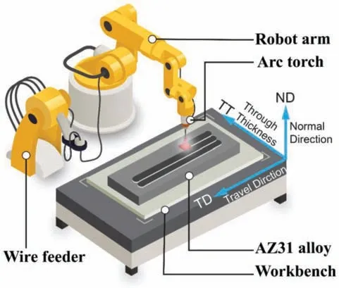
Fig.1.Schematic illustration of wire and arc manufacturing (WAAM) process.
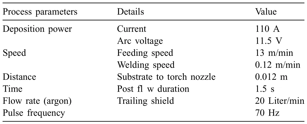
Table 1 Process parameters for WAAM deposition.
2.2.Characterization
2.2.1.Morphology and composition
Inductively coupled plasma atomic emission spectrometry(ICP-AES,Thermo iCAP 7000,USA) was used to determine the elemental composition of cast AZ31 and WAAM AZ31.The microstructure and grain orientation were analyzed by the SEM (ZEISS,MERLIN COMPACT) equipped with an HKL electron backscatter diffraction (EBSD) facility.The specimens for EBSD were polished by electrochemical polishing across the travel direction-normal direction (TD-ND) and travel direction–through thickness (TD-TT) section,and the step size of 1.8 μm and 0.4 μm was selected to acquire EBSD mapping with considering the grain size within the investigated surface.A scanning electron microscope (SEM,Tescan Vega3) equipped with an energy dispersive X-ray spectrometer (EDS) was used for further analyzing the surface morphology and elemental distribution before and after corrosion.X-ray diffraction(XRD)measurements were carried out using Ultimate IV diffractometer (Rigaku,Japan).X-ray diffraction patterns (2θ) were recorded from 25° to 80° using Cu Kα(λ=1.54,056) radiation at room temperature.The tube voltage and tube current were 40 kV and 40 mA respectively,whilst the scanning speed was 1.5°/min.
2.2.2.Electrochemical measurements
Interface 1010B potentiostat (Gamry,USA) was employed for potentiodynamic polarization and electrochemical impedance spectroscopy (EIS) measurements.A conventional three-electrode cell was used,in which the investigated specimens (i.e.cast AZ31 and WAAM AZ31) with 1 cm2exposed area served as the working electrode,a platinum (Pt)wire as the counter electrode and a saturated calomel electrode(SCE)as the reference electrode.All the electrochemical measurements were carried out in 0.5 wt.% NaCl solution at room temperature.To guarantee the reproducibility of results,all electrochemical measurements were repeated at least three times.
Before running the polarization measurement,the working electrode (i.e.cast AZ31 and WAAM AZ31) was immersed in the NaCl solution for 30 min to achieve a relatively stable open circuit potential (OCP).Since then,the charged potential shifts from OCP to −300 mV and 300 mV (vs.SCE)respectively in a scan rate of 0.5 mV/s.Furthermore,the EIS tests were performed in the frequency range from 105Hz to 10−2Hz with applying an amplitude of 10 mV RMS sinusoidal perturbation with respect to OCP.Commercial software Zview was employed for fittin the experimental impedance spectra.
3.Results
3.1.Composition,morphology and metallography analysis
It is well acknowledged that Mg alloys are extremely susceptible to impurities,e.g.iron (Fe),cobalt (Co) and nickel(Ni)etc.,which might be introduced during the whole production chain [16,17].The corrosion performance would be significantl deteriorated when the content of impurities in the bulk alloys exceeds their trace tolerance limits (i.e.Ni<5 ppm,Cu<1000–1300 ppm,Fe<170 ppm for pure Mg)[18,19].To ensure the corrosion properties of as-cast AZ31 and WAAM AZ31 are not affected by these mentioned impurities,the elemental composition of both candidates was primarily analyzed by ICP-AES.As listed in Table 2,the contents of alloying elements,i.e.aluminum,zinc and manganese,of cast AZ31 and WAAM AZ31 are in the standard range as mentioned in ASTM B91–12 [20].Besides,the values for the critical impurities are also strictly below their limitation,which indicate these detrimental impurities are notintroduced into the alloy during WAAM and their impact on the corrosion behaviors can be excluded.

Table 2 Chemical composition of as-cast AZ31 plate and WAAM AZ31 (wt.%).
Furthermore,X-ray diffraction was used to determine the phase composition of the cast AZ31 and WAAM AZ31 specimens,and the obtained XRD patterns are exhibited inFig.2.In addition to characteristicα-Mg peaks,much weaker Mg17Al12(PDF#01–1128) and Al86Mn14(PDF#45–1179) peaks are identifie on both cast AZ31 and WAAM AZ31.This difference in phase composition between two investigated candidates can be attributed to the different cooling rates from melting state.Comparing to casting,WAAM registers a much faster solidificatio rate which induces significan grain refinemen and diffusion of alloying element into Mg matrix.Furthermore,the microstructure of cast AZ31 base and WAAM AZ31 was observed in backscattering electron SEM mode (BSE) to facilitate the identificatio of the secondary phases (Fig.3) and EDS mapping (Fig.4) was employed to characterize their elemental composition.The interface between the WAAM deposit and the cast base can be clearly distinguished inFig.3(a) and (b)and rare defects as reported in [21] are found neither along the interface nor within the WAAM area,which confir the feasibility of parameters and motion regulation for WAAM.The cast AZ31 reveals more secondary phases (e.g.AlMn and MgAl phases) precipitated along the largeα-Mg grain boundaries(Fig.3(b) and (d)),whilst this condition are scarcely seen in the as-deposited WAAM AZ31 in the lower magnification Instead,the secondary phases within WAAM AZ31 are observed at higher magnification (Fig.3(d)and(f)),which distributed more uniformly among the surface of the matrix.EDS mapping of specifi areas (as indicated in red dot blanks inFig.3(b)–(f)) were carried to reveal the exact elemental composition of the secondary phase,and the results are given inFig.4.Significan difference can be observed in the interfacial EDS mapping (Fig.4(a)),where intensive alloying element distribution can be detected in the vicinity of grain boundaries with some weak ones within the grains for the cast AZ31 but this situation can rarely define for WAAM side.This result agrees well with the microstructure inFig.3.In higher magnificatio (Fig.4(b)and(c)),the irregularly shaped secondary precipitates within cast AZ31 can be simply identifie as AlMn and AlZn phases,whereas those tiny ones in WAAM are mainly AlMn phases.However,AlZn phase is not found in the reported XRD results,which may result from the low amount of alloying element addition that beyond the resolution of XRD at present input energy level.Besides,the absence of Zn-rich phase(s) in WAAM AZ31 may also suggest the solid solution of a majority of Zn withinα-Mg during WAAM,which benefit from the faster solidifi cation process.
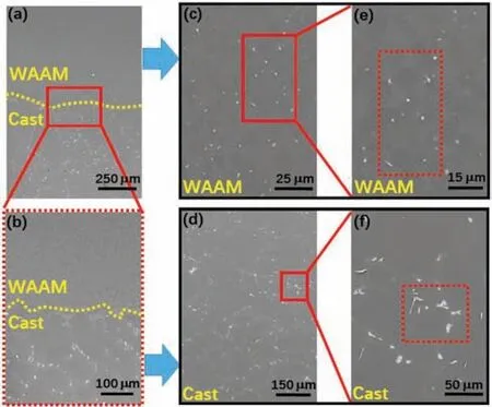
Fig.3.Microstructure of WAAM AZ31 and the cast AZ31 base.(a-b) interface between WAAM and cast AZ31 base,(c-d) cast AZ31 and (e-f) WAAM AZ31.
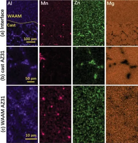
Fig.4.EDS mapping of the specifi areas (marked in red dash frame in Fig.3 of WAAM AZ31 and cast AZ31 base.(a) interface between the WAAM AZ31 and cast AZ31 base,(b) cast AZ31 and (c) WAAM AZ31.

Fig.5.EBSD analysis of WAAM AZ31.in (a) ND-TT direction and (b) TD-TT direction.
To investigate the influenc of WAAM process on the texturing of the AZ31 alloy,EBSD was conducted upon the well polished specimen.Fig.5displays the grain orientation map,inverse pole figur (IPF)and grain size distribution of WAAM AZ31 from the cross-sectional view (ND-TT direction) and top view (TT-TD direction),respectively.It can be generally seen fromFig.5that the grains of WAAM AZ31 exhibit typical equiaxed grain texture and the grain size is much smaller than that of the cast alloy.To be specific the size of the counted grains from the ND-TT view (Fig.5(a)) ranges from 6.4 μm to 30.5 μm (averaging at 12 μm),whilst those obtained from the TT-TD view (Fig.5(b)) are from 1.4 μm to 21.4 μm (averaging at 6.9 μm).This difference in the average value of grain size is highly possibly resulted from the quantity of statistical sample,which the number of grains involved in ND-TT view is almost quadruple that in the TTTD view.Nevertheless,the 9 -10 μm grains are more than the other size range under both conditions,which confir the consistency of both EBSD results.Furthermore,the crystallographic orientations of grains in {0001},{−12–10} and{01–10} along X,Y and Z direction are illustrated in inverse pole figur (IPF) for both views.It is indicative from the IPF contours that rather slight texture can be found upon the basal{0001}orientation along Y direction in the ND-TT plane,and{−12–10}orientation along X direction and{0001}and{01–10} orientation along Y direction in the TT-TD plane.Summing up,it can be suggested that the WAAM exerts grain refinemen but non-texturing of Mg alloys,which is expected to benefi the strengthening of the mechanical properties of Mg alloys.
3.2.Electrochemical results
3.2.1.Potentiodynamic polarization
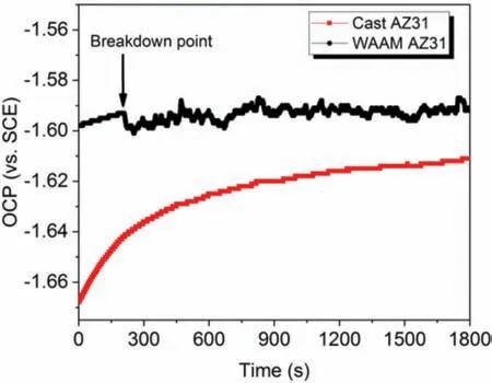
Fig.6.Open circuit potential (OCP) of cast AZ31 and WAAM AZ31 in 0.5 wt.% NaCl solution.
To investigate the free corrosion behaviors of cast and WAAM AZ31,OCP measurement was conducted in prior to potentiodynamic polarization for 30 min.As shown inFig.6,the OCP of cast AZ31 gradually increases from−1.668 V at the beginning to −1.611 V after 30 min immersion,which implies the oxidation of Mg and precipitation of corrosion products on the alloy surface.After that,the slope of this OCP curve decreases with time and stabilizes around −1.62 V,which suggests the kinetics of redox reaction tends to reach a relative balance state in the NaCl solution.As for the WAAM AZ31,the initial OCP is ca.0.07 V nobler (−1.60 V vs.SCE) than that of the cast counterpart,and then its value also anodically shifts to −1.59 V where the potential drops slightly followed by consecutive fluctua tion until the end of OCP measurement.This unstable state of OCP indicates the dissimilar kinetic and structure of hydroxide formation as the cast AZ31.This obvious difference in OCP between these two categories of AZ31 processed via different procedures indicates disparate corrosion behaviors,which may result from the grain refinemen and composition variation of the secondary phase(s).
The potentiodynamic polarization curves of the cast AZ31 and WAAM AZ31 were obtained after immersing in 0.5 wt.% NaCl solution for 30 min.As shown inFig.7(a),the corrosion potentials of as-cast AZ31 and WAAM AZ31 are stabilized around −1.559 V and −1.547 V respectively after 30 min immersion and their cathodic branches are almost overlapping with each other,which suggests the similar cathodic kinetics of H2O reduction with releasing H2(g).Despite this,significan difference can be obviously observed upon their anodic branches.In details,the cast AZ31 shows an initial pseudo passivation behavior,which is characterized by the slight reduction in increase rate of current density along with the consecutive shift of potential from OCP to nobler values.When the charged potential is higher than −1.305 V,the current density dramatically increases with the increasing potential indicating the damage of corrosion product layer.In contrast,WAAM AZ31 demonstrates an exponential increase of current density with respect to the potential growth,which suggests the refine alloy is more preferential oxidized and the resultant corrosion products layer is less protective than that deposited on the surface of cast AZ31 alloy.
Fig.7(b)illustrates the surface morphology in different magnification of both specimens after PDP.It can be seen that the control cast AZ31 exhibits typical filifor corrosion morphology,in which the corrosion attack generally initializes from one point and then spreads along the scratches introduced during the grinding preparation.Such a kind of morphology would suggest a dual corrosion mechanism of anodic polarized AZ31.It is undoubtable that the circular corrosion pits can be correlated with sites where micro galvanic corrosion between theα-Mg/eutectic Mg and secondary phases occurs,whereas the winding dendritic-like corrosion feature is derived from the anodic dissolution of Mg.In addition to the dark filifor corrosion areas,WAAM AZ31 also exhibits intergranular corrosion morphology on the corroded surface.This phenomenon can be ascribed to the grain refinemen and precipitation of secondary phases along the grain boundaries,which serve as the local cathodes accelerating the dissolution of Mg surrounding them.
3.2.2.Electrochemical impedance spectroscopy (EIS)


Fig.7.(a) Potentiodynamic polarization curves and (b) corresponding surface morphologies of cast AZ31 and WAAM AZ31 immersed in 0.5 wt.% NaCl solution with 30 min stabilization.
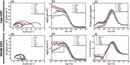
Fig.8.(a–c) EIS (Nyquist and Bode) curves of cast AZ31 and (d-f) WAAM AZ31 immersed in 0.5 wt.% NaCl solution at varied durations.

Fig.9.(a) Equivalent electric circuits (ECs) for simulating corrosion behaviors of cast AZ31 and WAAM AZ31 immersed in 0.5 wt.% NaCl solution at varied durations and (b) evolution of the overall impedance over 24 h immersion.
To quantify the physical-chemical behaviors during corrosion process,two sets of electrochemical equivalent circuit(EC) are used with considering corresponding EIS pattern,as shown inFig.9(a).The two time-constant spectra of the cast AZ31 are simulated by two relaxation processes constructed by the series connection of two groups of parallel-connected resistor(i.e.RfandRct)and constant phase element(i.e.CPEfandCPEdl),whilst the single time-constant spectra of WAAM AZ31 are fitte by the parallel connection of a resistor (Rct)and constant phase element(CPEdl).In these circuits,Rsis the resistance of the solution,CPEfandRfrepresent the constant phase element and resistance indicative of the capacitance and barrier properties of the corrosion products layer,CPEdlandRctare used to describe the capacitance of double layer and charge transfer resistance at the corroding metal/oxide interface [1].The replacement of pure capacitor by constant phase element is attributed to the consideration of the effect of surface roughness and non-uniform diffusion behaviors [23,24].The overall impedance (Rall) of cast AZ31 is calculated with summatingRfandRct(i.e.Rall=Rf+Rct),whilstRallequals toRctfor WAAM.Fig.9(b)shows the evolution ofRallfor both groups during the 24 h EIS measurement.TheRallof the cast AZ31 increases from 3.4 kohm•cm2at the initial to 5.8 kohm•cm2after 6 h immersion,which is followed by a significan reduction to 1.1 kohm•cm2by 24 h.Unlike the fluctuatinRalltrend for the cast AZ31,WAAM AZ31 remains a moderate (approx.1.6 kohm•cm2) but relatively stable state during the 24 h immersion.It can be claimed that the significan difference in EIS results between both specimens is mainly resulted from the formation of hydroxide layer on the surface of alloy.The hydroxide layer can simultaneously form on the top of cast AZ31 providing temporary corrosion protection until 6 h,after which this layer is broken down resulting in consecutive reduction of the systematic impedance.As for WAAM AZ31,the formation of integrated hydroxide layer is retarded since the initial of immersion,and thus it is not expected to render protection of the alloy against corrosion attack.Overall,formation and growth of the hydroxide layer plays a decisive role in enhancing the corrosion resistance of Mg alloy.The properties of the hydroxide layer is determined by the combination of chemical composition,microstructure,crystallographic texture and grain size of metals,which decides the specifi breakdown value (Ecorr)of the hydroxide layer [25].
3.3.Corroded surface analysis
The corroded surface morphologies of cast AZ31 and WAAM AZ31 recorded after 24 h EIS measurement are shown inFig.10.The exposed surface of both specimens can be briefl categorized into corrosion damaged areas(Fig.10(a1),(a2),(b1)and(b2)) and relatively intact areas(Fig.10(a3),(a4),(b3)and(b4)),respectively.Distinct corrosion morphologies can be observed from the general view (Fig.10(a) and (b)) of the exposed area for both specimens,which again suggest dissimilar corrosion behaviors.Cast AZ31 reveals a filiform-li e corrosion feature,in which the attack mainly occurs within theα-Mg grains and their development is terminated by the grain boundaries.The uncorroded area on cast AZ31 demonstrates net-like surface morphology (Fig.10(a3)),where hydroxide preferentially precipitates upon the surface ofα-Mg grains but deteriorates with time due to their less compact nature (Fig.10(a4)).WAAM AZ31 reveals a higher corroded area (Acorr) to intact area (Ainta) ratio comparing to that of the cast AZ31,and the damaged surface is featured by individual tiny pores(Fig.10(b)).When getting closed to the surface,exfoliation of a whole grain can be witnessed within the corroded area(Fig.10(b1) and (b2)),which indicates the intergranular corrosion mechanism of WAAM AZ31.Dendrite-like morphology feature is found upon the undamaged region of WAAM AZ31,but the it is hard to distinguish and judge the impact of secondary phases on the corrosion behaviors of the WAAMed alloy.For a better understanding of the degradation process,both specimens were cleaned in CrO3solution(180 g L−1) to remove the corrosion products.As shown inFig.11(a),the cleaned cast AZ31 exhibits an island-like surface morphology,in which the boundaries ofα-Mg grains diminish leaving the almost unaffected secondary precipitates there.Such a phenomenon can suggest that the micro galvanic coupling betweenα-Mg and the secondary phases plays the most critical role in triggering the corrosion of the cast alloy.In contrast,WAAM AZ31 demonstrates much more porous surface than cast AZ31 after removing the corrosion products(Fig.11(b)).More importantly,the secondary phases can hardly be observed among the surface (even in higher magnification as the inset inFig.11(b)),which implies that galvanic coupling betweenα-Mg and secondary phases is probably not the critical factor to initialize the corrosion of alloy.The cross-sectional view (Fig.12) of both specimens after 24 h immersion in NaCl solution correlates well with the top view morphology.Individual and regular corrosion spots are found on the cast AZ31,whereas WAAM AZ31 illustrates a relative uniform corrosion condition.

Fig.10.Corroded surface morphology after 24 h EIS measurement in 0.5 wt.% NaCl electrolyte (a) cast AZ31 and (b) WAAM AZ31.
4.Discussion
4.1.Grain refinemen mechanism
Grain size is well recognized as a pivotal microstructural factor in determining the mechanical properties of Mg alloys,and the strength,ductility,creep and fatigue resistanceetc.of Mg alloys increase with reducing the grain size [26].To achieve this end,various strategies,i.e.severe plastic deformation,heat treatment and alloying or chemical additionetc.,have been proposed for attaining the effect of grain refine ment.Differing from the conventional casting and wrought techniques,WAAM employs metallic wire as the raw material,which is locally melted by intensive electric energy density formed due to the occurrence of short circuit.As a result,the heat input is strictly restricted (lower than the heat input required for spray transfer) and the solidificatio of melting metallic beads is faster,resulting in more homogeneous and less affected by the bulk volume effect comparing to casting and wrought process.Such an assertion has been confirme by the EBSD crystallographic analysis (Fig.5),in which the WAAM AZ31 reveals much refine grains.This grain size has generally reached the grain level of AZ31 manufactured by most advanced severe plastic deformation,and thus,it is reasonable to expect enhanced mechanical strength of WAAM alloy [26].In addition to grain refinement the WAAM AZ31 also reveals none textured equiaxial crystallography,which may also result from the transient solidificatio process of melting Mg beads since they leave the end of the wire until contact the surface of Mg plate.However,such an optimized microstructure of WAAM AZ31 is controversial to the dentrites dominant microstructure most recently reported by Wang et al.[15] and Yang et al.[8]..This contradiction in microstructure can be critically related with selection of electric parameters of power source,the motion regulation of wire (e.g.scanning speed and retract speed at short circuit),the cooling effect of argon and heat effect caused by the multi upper layer scanetc.However,this topic is far more beyond the focus in the present work and will be reported as follow in our coming publications.
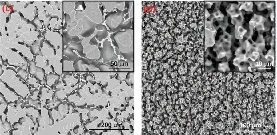
Fig.11.Oxide-removed surface morphology of (a) cast AZ31 and (b) WAAM AZ31 after 24 h EIS measurement in 0.5 wt.% NaCl electrolyte.

Fig.12.Corroded cross section morphology after 24 h EIS measurement in 0.5 wt.% NaCl electrolyte (a) cast AZ31 and (b) WAAM AZ31.
4.2.Influenc of grain refinemen on the corrosion mechanism of AZ31

Fig.13.Schematic illustration of corrosion mechanisms of (a) cast AZ31 and (b) WAAM AZ31.
As known,Al is preferentially to form Mg-Al and Al-Mn intermetallic in Mg alloys especially for AZ and AM series.As verifie in [27,28],the Volta potential of is Al-Mn and Mg-Al (β-Mg17Al12) phase is ca.300–400 mV (vs.SHE) and 50–200 mV (vs.SHE) nobler than that ofα-Mg,which indicates the corrosion of AZ and AM alloys in neutral aqueous environment generally results from the galvanic coupling between Al-Mn/Mg-Al andα-Mg,in whichα-Mg(active anode) is consumed with leaving the cathodic secondary phases protected.During this process,Mg(OH)2precipitates on the alloy surface when the concentration of Mg2+and OH−from the redox corrosion reactions is over the solubility (Ksp=3×10⁻¹¹mol3dm−9) of Mg(OH)2in water[29].However,such a hydroxide layer can barely function as a tough barrier like the passivation layers formed upon aluminum and titanium alloys that significantl impede the penetration of corrosive speciese.g.Cl−,but is broken down at local sites as implied in the free OCP curve inFig.6.This process is not only influence by the concentration of NaCl solution [25] but the element distribution,microstructure and grain size of the alloy.After the breakdown of the Mg(OH)2layer,individual dark spots (anodes) appear on the surface and then some of them consequently branch into tracks resulting in filifor corrosion morphology until full coverage of the exposed area.Since then,the corrosion behaviors of AZ31 become cathodically activated as manifested by thein situscanning vibrating electrode technique (SVET) [25].
According to the electrochemical results (Figs.7 and 8),it can be suggested that the WAAM alloy reveals less advantageous corrosion performance in pH neutral NaCl solution than the cast one.It is widely acknowledged that the corrosion properties of Mg alloys are dependent on crystallographic texture and grain size when the chemical and phase composition are rather similar.The basal (0001) plane of Mg employing the highest atomic density of 1.13×10¹⁹atoms•m−2reveals the lowest corrosion tendency than those non-basal planes,which can be correlated with its lowest surface energy that requires more activation energy for dissolution [30,31].In spite of this,specifi texture behaviors can hardly be identifie upon WAAM AZ31 alloy (Fig.5),which implies the difference in corrosion performance mainly result from the variation in grain size.However,the effect of grain size on the corrosion behaviors of Mg alloys remains controversial among the known literatures.As a mainstream of this divergence,a majority of researchers found that the corrosion rate of Mg alloys decreases with reducing the grain size of alloys processed via rolling [31,32],friction stir processing (FSP)[33,34] and equal-channel angular pressing (ECAP) [35]etc.Some of them ascribed the enhancement of corrosion resistance of the grain refine alloy to the barrier property of grain boundary or facilitate passivation of Mg that impedes corrosion attack propagation between grains,while the others attributed such an enhancement to the physical breakdown of secondary phases.In contrast,deterioration in corrosion performance of Mg alloys with reducing the grain size was reported and experimental validated by Song and Xu [36] and Zhang et al.[37],who claimed that grain boundaries,similar to dislocations and twins,were denoted as crystallographic defects that were more susceptible to corrosion attack than the grains and thus facilitate corrosion of Mg alloys.To explain this difference,Ralston et al.correlated the corrosion behaviors of metallic alloys with the film formed during immersion [38].They suggested that grain refinemen would induce different rates in oxide fil growth,which in turn restricts the anodic reactions rate but has nothing to do with cathodic branches since the cathodic reaction relies more on electronic conduction than ionic conduction.The experimental results shown in our present research consolidate the later assumption,and the effect of grain size on the corrosion mechanism of AZ31 is explained,as shown inFig.13.For cast AZ31,employing largeα-Mg grain and secondary phases,microgalvanic coupling between secondary phases located within a-Mg and along the grain boundaries (Figs.3and4) can be define as the most critical factor that triggers the corrosion initialization of cast AZ31.Simultaneously,hydroxide inhomogeneously deposits on the surface of corroding alloy,where more precipitates are found around those active sites than theα-Mg areas.Even though,a relative integrated hydroxide layer can form on the alloy surface providing temporary protection against corrosion attack until its failure due to the intrinsic porous property (Fig.13(a)).As for WAAM AZ31 (Fig.13(b)),the integrity of the hydroxide layer is much worse than that on the cast AZ31 as the factor of grain size overweighs that of the micro-galvanic coupling,and thus,corrosion attack is more preferentially occurred along the abundant grain boundaries (Fig.10(b)).Without the protection of hydroxide film the anodic electrochemical kinetics of WAAM AZ31 almost follows the same pattern as that of the cathodic branch (Figs.7and8),and relative uniform corrosion degradation can be expected that benefit the determination of corrosion rate in practical engineering applications.
In a general view of the present research,wire and arc additive manufacturing (WAAM) illustrates great potential in producing Mg alloys.The WAAM AZ31 alloy reveals a refine crystallographic microstructure featured by sizereduced and non-textured grains,which can bring enhanced and isotropic mechanical strength when comparing with other Mg processing techniques.In terms of corrosion performance,WAAM AZ31 also shows deteriorated degradation behaviors than the cast alloy,and this difference is mainly caused by the factor of grain size.With significan reduction of grain size,WAAM AZ31 is prone to suffer intergranular corrosion attack during its immersion in NaCl solution,which greatly reduces the integrity of the hydroxide layer.To sum up,the exploration on the properties of additive manufactured Mg alloys is still on the horizon,which deserves a further and deep investigation.
5.Conclusion
In the present study,AZ31 Mg alloy was printed as a single layer through wire and arc manufacturing (WAAM)-cold metal transfer (CMT) on the top of cast AZ31 surface.Influenc of WAAM on the microstructure,phase composition and corrosion behaviors were investigated in comparison with those of cast AZ31.Combining all the obtained results,three principal conclusions can be drawn as follow:
1.Through path planning and parameters optimization,a single AZ31 Mg alloy layer was successively deposited upon the Mg base featured by homogeneous structure and rare defects at the interfacial region.
2.Unlike the microstructure of cast Mg alloys,the WAAM AZ31 exhibits significan grain refinemen (average size of~12 μm in ND-TT direction and~6.9 μm in TT-TD direction),non-textured crystallographic orientation and homogeneous microstructure.In addition toα-Mg,trace of Mg17Al12and Al86Mn14phases are found in WAAM AZ31,which may benefi from the fast solidificatio during WAAM.
3.WAAM AZ31 reveals deteriorated but relative stable corrosion behaviors in comparison with those of the cast AZ31.These variations in corrosion performance are mainly caused by the factor of grain size.The corrosion mechanism of the cast alloy with large grains is dominated by the micro galvanic coupling betweenα-Mg and secondary phases,whereas intergranular corrosion is prevalent over the micro galvanic corrosion when the grain size is significantly declined.
Declaration of Competing InterestThe authors declare that they have no conflict of interest to this work.We declare that we do not have any commercial or associative interest that represents a conflic of interest in connection with the work submitted.
Data availability
The raw/processed data required to reproduce these find ings cannot be shared at this time as the data also forms part of an ongoing study.
CRediT authorship contribution statementJianwei LI:Conceptualization,Formal analysis,Writing–original draft.Youmin QIU:Investigation,Visualization,Formal analysis,Validation,Writing–review &editing.Junjie YANG:Conceptualization,Investigation,Formal analysis,Visualization,Writing– original draft.Yinying SHENG:Investigation,Visualization.Yanliang YI:Investigation,Formal analysis.Xun ZENG:Formal analysis,Visualization.Lianxi CHEN:Resources,Writing– review &editing.Fengliang YIN:Investigation,Formal analysis,Writing–review&editing.Jiangzhou SU:Investigation,Formal analysis,Visualization,Writing– original draft.Tiejun ZHANG:Supervision,Formal analysis,Validation,Writing– review &editing.Xin TONG:Conceptualization,Formal analysis,Writing–review&editing.Bin GUO:Supervision,Formal analysis,Writing– review &editing.
AcknowledgmentTechnical support and discussion from Qiang ZHANG and Yunlong HU is acknowledged.Junjie Yang appreciates the financia support by National Key Research and Development Project (Grand No.2020YFC1107202),Guangdong Basic and Applied Basic Research Foundation (Grand No.2020A1515110754),MOE Key Lab of Disaster Forest and Control in Engineering,Jinan University (Grand No.20200904008),Educational Commission of Guangdong Province (Grand No.2020KTSCX012) and the Fundamental Research Funds for Central Universities (Grand No.21620342).Fengliang Yin acknowledges the support from National Natural Science Foundation of China,NSFC (Grand No.51775556).
杂志排行

Journal of Magnesium and Alloys的其它文章
- Development of high-strength magnesium alloys with excellent ignition-proof performance based on the oxidation and ignition mechanisms: A review
- Development and application of magnesium alloy parts for automotive OEMs: A review
- Recent advances in surface endothelialization of the magnesium alloy stent materials
- Recent developments in high-pressure die-cast magnesium alloys for automotive and future applications
- Exploring the contribution of oxygen reduction reaction to Mg corrosion by modeling assisted local analysis
- Microstructures,mechanical properties,corrosion,and biocompatibility of extruded Mg-Zr-Sr-Ho alloys for biodegradable implant applications