Developing new Mg alloy as potential bone repair material via constructing weak anode nano-lamellar structure
2023-03-24JinshuXieLeleWngJinghuiZhngLiweiLuZhiZhngYuyingHeRuizhiWu
Jinshu Xie,Lele Wng,Jinghui Zhng,∗,Liwei Lu,Zhi Zhng,Yuying He,Ruizhi Wu
aKey Laboratory of Superlight Material and Surface Technology,Ministry of Education,College of Materials Science and Chemical Engineering,Harbin Engineering University,Harbin,150001,China
b School of Materials Science and Engineering,Hunan University of Science and Technology,Xiangtan,411201,China
Abstract The mechanics-corrosion and strength-ductility tradeoffs of magnesium (Mg) alloys have limited their applications in field such as orthopedic implants.Herein,a fine-grai structure consisting of weak anodic nano-lamellar solute-enriched stacking faults (SESFs) with the average thickness of 8 nm and spacing of 16 nm is constructed in an as-extruded Mg96.9Y1.2Ho1.2Zn0.6Zr0.1 (at.%) alloy,obtaining a high yield strength (YS) of 370 MPa,an excellent elongation (EL) of 17%,and a low corrosion rate of 0.30 mm y−1 (close to that of high-pure Mg) in a uniform corrosion mode.Through scanning Kelvin probe force microscopy (SKPFM),one-dimensional nanostructured SESFs are identifie as the weak anode (∼24 mV) for the firs time.The excellent corrosion resistance is mainly related to the weak anodic nature of SESFs and their nano-lamellar structure,leading to the more uniform potential distribution to weaken galvanic corrosion and the release of abundant Y3+/Ho3+ from SESFs to form a more protective fil with an outer Ca10(PO4)6(OH)2/Y2O3/Ho2O3 layer (thickness percentage of this layer: 72.45%).For comparison,the as-cast alloy containing block 18R long period stacking ordered (LPSO) phase and the heat-treated alloy with fin lamellar 18R-LPSO phase (thickness: 80 nm,spacing: 120 nm) are also studied,and the characteristics of SESFs and 18R-LPSO phase,such as the weak anode nature of the former and the cathode nature of the latter (37-90 mV),are distinguished under the same alloy composition.Ultimately,we put forward the idea of designing Mg alloys with high mechanical and anti-corrosion properties by constructing "homogeneous potential strengthening microstructure",such as the weak anode nano-lamellar SESFs structure.
Keywords: Mg alloys;Corrosion;Solute-enriched stacking faults;LPSO structure;SKPFM;Hydroxyapatite.
1.Introduction
Magnesium (Mg) alloys have attracted much attention for their potential use in a new way as biodegradable medical implant materials due to some of their advantages,such as good biodegradability,biocompatibility,similar density and elastic modulus with natural bones [1–5].As a Mg-based bone repair/fixatio material,in addition to biocompatibility,it is required to be high strength,good plasticity,and corrosion resistance (biodegradability),as well as stimulating bone growth all in one.Erinc et al.[3] suggested the ideal mechanical and anti-corrosion properties of Mg alloys for bone repair/fixatio devices,i.e.,yield strength (YS)>300 MPa,elongation (EL)>10%,and corrosion rate ≤0.5 mm y−1.However,the mechanics vs.anti-corrosion and strength vs.ductility tradeoffs of Mg alloys have always been the critical issues that seriously hinder their wide orthopedic applications[6–10].
Mechanics-corrosion tradeoff.Precipitation strengthening(micro-nano scale secondary phase particles) is one of the most important strengthening methods of Mg alloys.However,quite a few strengthening phases in Mg alloys exhibit a nobler corrosion potential thanα-Mg matrix,such as Mg17Al12(80-225 mV [11,12]),MgZn2(475 mV [12]),Mg2Sc (550 mV[13]),and Al8Mn5(250-550 mV [11,14]).The large potential difference (PD) between such strong cathode phases and Mg matrix would lead to the formation of the micro-galvanic couple and finall initiate and boost localized corrosion of the Mg matrix.More recently,a few secondary phases acting as weak anodes are also found in Mg alloys,such as MgGdYNd(35 mV [15]) in EW75 alloy and Mg2Ca (75 mV [16]) in Mg-1Ca alloy,which are considered likely to have relatively low impact to the corrosion sensitivity of alloys [15–17].Certainly,in addition to the electrochemical characteristics (cathodic/anodic or PD),the size,morphology,and distribution of the strengthening phases also influenc the corrosion behavior [8,18–20].A typical example in previous studies is the influenc of the Mg17Al12phase on the corrosion behavior of Mg-Al series alloys [21–23].If the Mg17Al12particles are small and their distribution is discontinuous,the galvanic effect would govern the corrosion of an alloy.On the contrary,the net-like Mg17Al12phase can act as a barrier to retard the corrosion propagation of Mg alloys to some extent.From the kinetics investigation of corrosion,the poor corrosion resistance of common Mg alloys is related to the lack of compactness and protection of surface film [24–28].Fortunately,the addition of rare earth (RE) elements is considered to be an effective way to compensate for this defect [29–35].Leleu et al.[29] proposed that the addition of RE elements (Y and Nd) can contribute to forming the passive surface fil during the corrosion process,thereby improving the corrosion resistance of Mg alloys.The size,morphology,and distribution of the secondary phases also have a key impact on the formation of protective film in addition to the alloying element [32,34–36].Feng et al.[32] reported that the large Mg41Sm5phase particles with net-like morphology along the grain boundary in the as-cast alloy play the role of strong cathodes,resulting in the accumulation of thick but loose corrosion film while the dispersed fin Mg41Sm5particles in the as-extruded alloy are more conducive to the formation of homogeneous Sm2O3quasi-passivation film Based on the above mentioned points,it is deduced that the formation of strengthening structure with tiny PD,small size,and uniform distribution in Mg-RE alloys may be the optimal choice to deal with the mechanicscorrosion tradeoff.
Strength-ductility tradeoff.Synergistic improvement of strength-ductility is always a common goal pursued by researchers of all metallic materials,including Mg alloys.It is known that grain refinemen can generally improve strength and ductility simultaneously,but it is not easy to achieve substantial improvement of mechanical properties,especially strength,by grain refinemen alone.The secondary phase strengthening,especially nano precipitation,is well recognized as a very effective way to improve the strength of Mg alloys.Some age-hardenable Mg alloys with high RE content have been known as the typical high-strength Mg alloys,such as Mg-13Gd [37],Mg-8Gd-3Y-0.4Zr [38],etc.However,a large number of those secondary phase particles usually make the alloys obtain excellent strength at the expense of ductility by hindering dislocation movement.Recently,the lamellar structures,including stacking faults (SFs) or long period stacking ordered (LPSO) structure,have been introduced into Mg alloys to further develop new high strength-ductility Mg alloys[39–43].For example,Xu et al.[41]developed the Mg-8.2Gd-3.8Y-1.0Zn-0.4Zr alloy with high strength (YS: 379 MPa) and ductility (EL: 14.7%) via constructing the bimodal structure containing SFs.Therefore,the fine-grai structure containing nano-spaced SFs should be a superior alloy structure to provide high strength-ductility.
The current study aims to develop a new Mg alloy with high mechanical and anti-corrosion properties for orthopedic applications via constructing the fine-grai structure containing weak anode nano-lamellar SFs,and mainly to explore the corrosion behavior of this alloy in simulated body flui(SBF) solution.The results show that the as-extruded alloy has an excellent combination of high strength-ductility (YS:370 MPa,EL: 17%),excellent corrosion resistance (corrosion rate: 0.30 mm y−1),and beneficia effect for bone repair due to the formation of corrosion fil containing abundant hydroxyapatite (HA,Ca10(PO4)6(OH)2).In addition,our studies[44] and previous reports [31] have demonstrated that Ho and Y have acceptable biocompatibility.The newly designed high-performance Mg alloy exhibits a superior biomedical potential.
2.Experimental
2.1.Alloying design
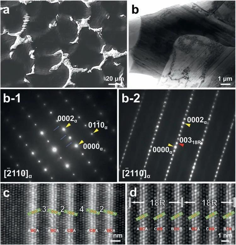
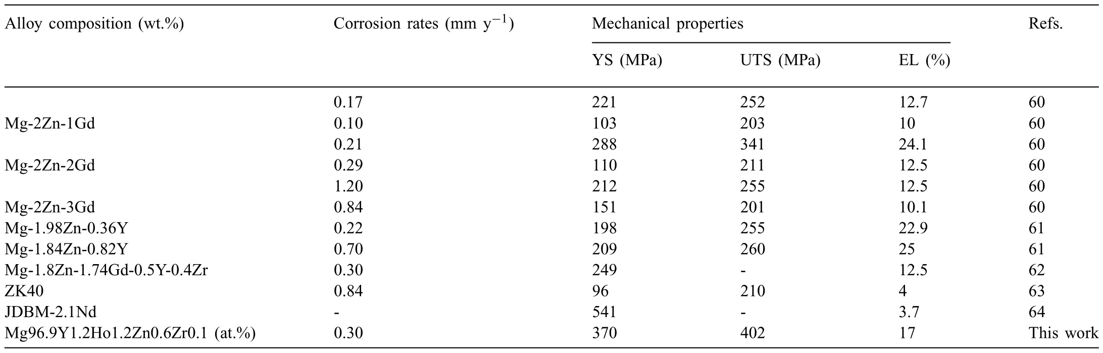
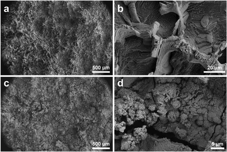
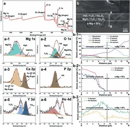
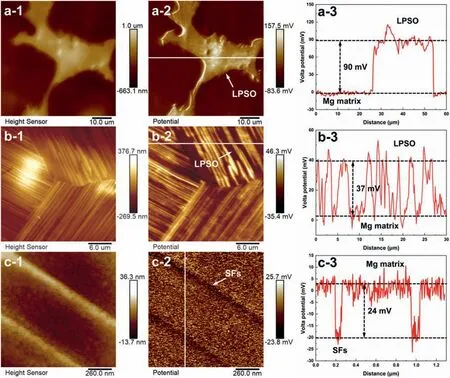
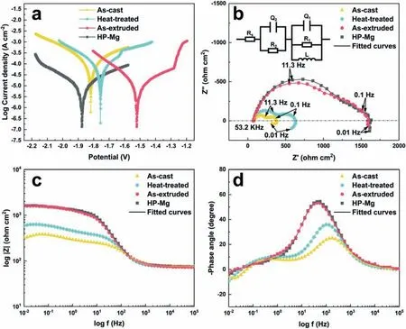
Based on the previous reports and our studies [8,42,44–48],the formation criteria of LPSO phase and SFs structure in Mg-RE-Zn (RE=Y,Ho,Er,Dy,and Tm) alloys was summarized as follows.(a) It is easy to form the LPSO phase when atomic ratio RE/Zn=2,and to form SFs structure when RE/Zn increases (i.e.,RE/Zn>2).(b) Specificall,the nanospaced SFs can be formed in Mg alloys in accordance with the following composition: Mg100-a-bREaZnb(RE=Ho,Y,and Er;1 The cast ingots were prepared by melting the mixture of high-pure Mg (99.99 wt.%),pure Zn (99.98 wt.%),Mg-21Ho(wt.%),Mg-22Y (wt.%),and Mg-30Zr (wt.%) master alloys.The raw materials were melted at about 750°C in an electric resistance furnace under the protection of Ar inert atmosphere.After complete melting,the alloy melt was stirred at about 740°C for 15 min and then refine at 760°C for 5 min by injecting Ar gas into the melt.After standing at 750°C for 30 min,the melt was cooled to 720°C,the surface scum was scraped off,and then the melt was poured into a water-cooled steel mold under the protection of Ar gas.Finally,the billet with a diameter of 92 mm and length of 750 mm was obtained.The actual chemical composition was analyzed by an inductively coupled plasma-atomic emission spectrometer(ICP-AES,Thermo iCAP 7400),as listed in Table 1. Table 1 Chemical composition of the alloy determined by ICP-AES. Table 2 Detailed ion concentrations of the SBF solution. Part of the ingots were heat-treated at 530°C for 14 h,and then cooled in the furnace to room temperature with the speed of ∼0.7°C min−1(i.e.,the heat-treated alloy);while some other ingots were immediately quenched in the warm water of about 80°C after solid solution treatment at 530°C for 14 h to prepare for subsequent hot extrusion.The cylindrical billets with dimensions ofφ82 mm×100 mm were machined from the solid solution-treated samples.After preheated at 360°C for 1 h,the above billets were extruded at 360°C under an extrusion speed of 1 mm s−1with an extrusion ratio of 23.Finally,three alloys were obtained,i.e.,as-cast alloy,heattreated alloy,and as-extruded alloy.In addition,as a reference,high-pure Mg was also extruded at the same extrusion ratio at 300°C (marked as HP-Mg). The scanning electron microscope (SEM,Apreo S LoVac,Thermo Fisher,USA) equipped with nordlysmax3 electron backscatter diffraction (EBSD) system was used to characterize microstructural features.The samples for SEM observation were etched with picric acid solution (0.42 g picric acid,1 mL acetic acid,1 mL distilled water,and 7 mL ethanol).The EBSD specimens were ion milled on a Leica RES101 after mechanical polishing.The EBSD data were collected with a scanning step size of 150 nm at 20 kV.The results for EBSD were dealt with the orientation imaging microscopy softwares HKL-Channel 5 and Azteccrystal 2.0.The transmission electron microscopes (TEM),including a Talos F200X (Thermo Fisher,USA) and a double aberrationcorrected Titan3TMG2 (Thermo Fisher,USA),were used to obtain bright-fiel images and atomic-resolution high-angle annular dark-fiel (HAADF) images.The thin foils for TEM were prepared by ion-milling using a PIPS II system (Gatan 695,USA) at -30°C. The surface potential distribution was measured by the scanning Kelvin probe force microscopy (SKPFM) (Dimension Icon,Bruker).Prior to the SKPFM test,the specimens with dimensions of 8 mm×8 mm×5 mm were ground,then mechanically polished and supplemented by electrolytic polishing to smooth the sample surface to the greatest extent.SKPFM measurements were operated in dual scan mode,using a magnetically etched silicon probe (MESP-V2,k=3 N m−1,Bruker Corporation,CA,USA).The tapping mode was used to obtain the surface morphology signal,and the cantilever was raised by 80 nm to record the potential signal in the scanning area.At least 3 samples of each alloy were measured,and these measurements were made at room temperature with relative humidity controlled below 40%.The data were analyzed by the nanoscope analysis 1.9 software. The tensile specimens with a gauge length of 20 mm,a width of 4 mm,and a thickness of 2 mm were immersed in SBF solution at 37±0.5°C for 0,7,and 14 days.At least 3 specimens for each state were tested along extrusion direction(ED) by an Instron 5569 universal testing machine at room temperature,with an initial strain rate of 1×10⁻³s−1. The hydrogen evolution and weight loss tests were conducted by immersion tests [49,50].Samples with 30 mm×15 mm×3 mm were performed in SBF solution.The ion concentrations in the SBF were listed in Table 2.The temperature of the SBF was maintained at 37±0.5°C using a water bath.The SBF was buffered with Tris-HCl,and the pH was kept at 7.4.The evolved hydrogen was collected above the specimen by means of a funnel and burette during the immersion experiment.The SBF was refreshed every 12 h in order to keep the solution concentration stable.The hydrogen volume values were recorded every 2 h,and the pH values were recorded every 12 h.The samples immersed for 7 days immersion were obliterated the corrosion products by using the chromate acid of 100 g CrO3,5 g AgNO3,and 500 mL deionized water,then washed with deionized water and dried by cold air,followed with weighting to gain the weight loss.Each immersion test was performed at least three times. Fig.1.Microstructure of the as-cast alloy: (a) SEM and (b) bright-fiel TEM images;(b-1) and (b-2) SAED patterns of (b);(c) atomic-resolution HAADF image of fin SESFs structure;(d) atomic-resolution HAADF image of block 18R-LPSO phase. The corrosion morphology and the surface fil after immersion for 7 days were characterized by SEM (Apreo S LoVac,Thermo Fisher,USA).The elements and their distributions in the cross-section of corrosion fil were analyzed using an energy dispersive spectroscope (EDS) in SEM by line and mapping scannings.The composition of surface fil was also analyzed by an X-ray photoelectron spectroscope(XPS,ESCALAB 250Xi,ThermoFisher,USA) equipped with Al Kαradiation (1486.6 eV) with a step scanning of 0.05 eV. All electrochemical tests were carried out with a CS350H(Corrtest instrument co.,China) electrochemical workstation through a standard three-electrode system: Mg alloy specimen as the working electrode with the exposure area of 1 cm2,platinum mesh as the counter electrode,and saturated calomel electrode (SCE) as the reference electrode.Potentiodynamic polarization (PDP) and electrochemical impedance spectroscopy (EIS) tests were carried out in SBF solution and were recorded after 2 h stabilization at open circuit potential(OCP).The PDP was performed over a potential range from -300 mV to +300 mV relative to the OCP at a scan rate of 0.5 mV s−1.The EIS measurements were measured at the OCP in the frequency range from 100 kHz to 0.01 Hz with a 5 mV perturbing sinusoidal signal.Zsimpwin software was used to analyze and fi EIS data.All electrochemical measurements were carried out at 37±0.5°C,and at least 3 specimens were tested in electrochemical tests for each alloy to ensure data accuracy. Fig.2.Microstructure of the heat-treated alloy: (a) SEM and (b) bright-fiel TEM images;(b-1) SAED pattern of (b);(c) atomic-resolution HAADF image of fin 18R-LPSO lamellae. Fig.1(a)–(d) show the microstructure of as-cast alloy.The as-cast alloy is mainly composed ofα-Mg equiaxed dendrites with an average grain size of 35.8 μm,semi-continuous intermetallic compounds along the grain boundaries (GBs),and superfin lamellae around the GBs (Fig.1a and b).The average thickness and spacing of these fin lamellae are about 20 nm and 55 nm,respectively;they seem to grow from GBs to grain inwards,but most of them only distribute near GBs,that is,there are almost no such fin lamellae in the grain center.The selected area electron diffraction (SAED) pattern suggests that these fin lamellae have basal plane SF structure (Fig.1b-1),and the atomic-resolution HAADF-STEM image further confirm that they are I2-type SFs with ABCAtype stacking sequence (Fig.1c).Note that the two internal layers with local face-centered cubic (fcc) structure exhibit brighter contrast than the two outer layers,indicating the solute atoms with higher atomic numbers than Mg are enriched in the inner layer,that is,the fin lamellae are the soluteenriched SFs (SESFs) [51].In addition,the number of Mg layers sandwiched between each two adjacent SESFs is generally different [40,52,53].The SAED pattern and the atomicresolution HAADF-STEM image identify that the bulk intermetallic compounds are 18R-LPSO phase with the stacking sequence of ABABCACACABCBCBCABA and periodic solute enrichment (Fig.1b-2 and d).It should be noted that the LPSO phase is constructed by the periodic structural unit composed of hexagonal close-packed (hcp) Mg layers and fcc SESFs [40,52,53]. Fig.3 exhibits the microstructure of as-extruded alloy.It reveals that the as-extruded alloy dominantly consists of the fine-equia ed dynamic recrystallized (DRXed) grains(Fig.3a),and the average grain size is just 1.8 μm analyzed by EBSD (Fig.3d).The (0001) pole figur and inverse pole figur (IPF) referring to normal direction (ND) reveal that the as-extruded alloy has a weak basal texture (Fig.3d-1 and d-2).More importantly,profuse superfin lamellae are formed in the DRXed grains during hot extrusion,and the orientation of these lamellae varies among different grains.Fig.3(b) shows the internal structure of a typical DRXed grain.These superfin lamellae are densely and uniformly distributed throughout the grain,their length is approximately the same as the grain size,and their average thickness and spacing are about 8 nm and 16 nm,respectively.From the results of the SAED pattern and atomic-resolution HAADFSTEM image (Fig.3b-1 and c),it can be determined that these superfin lamellae are also I2-type SESFs with ABCAtype stacking sequence. Fig.3.Microstructure of the as-extruded alloy: (a) SEM and (b) bright-fiel TEM image;(b-1) SAED pattern of (b);(c) atomic-resolution HAADF image of SESFs;EBSD analysis including (d) IPF map,(d-1) (0001) pole figure and (d-2) IPF referring to ND. Fig.4.(a) Tensile stress-strain curves of Mg-Y-Ho-Zn-Zr alloys with different states and HP-Mg;(b) distribution map of YS and EL of the studied alloy and other reported Mg alloys with biomedical potential [9,31,44,55-64].Note that the dotted lines represent the criteria of the strength and elongation in orthopedic-application Mg alloys,respectively. Fig.5.(a)Hydrogen volume variations with the immersion time;(b)average corrosion rates calculated from the weight loss and hydrogen volume measurements after immersion in SBF solution for 7 days;(c) variations of pH values of the immersed solutions with the immersion time. Fig.4(a) shows the tensile stress-strain curves of as-cast,heat-treated,and as-extruded alloys as well as HP-Mg.As expected,the HP-Mg exhibits both low tensile strength and ductility even in the as-extruded state.Through ingenious alloying design,the YS,ultimate tensile strength (UTS),and EL of as-cast alloy are about 130 MPa,250 MPa,and 11%,respectively,and the tensile properties,especially EL,are further improved by heat treatment,which is about 130 MPa,281 MPa,and 15%,respectively.Most notably,the studied alloy after hot-extrusion exhibits an excellent strength-ductility combination.The YS,UTS,and EL of as-extruded alloy are 370 MPa,402 MPa,and 17%,respectively,and the product of strength and elongation (PSE) is 6.8 GPa %.It should be emphasized that the proposed ideal YS and EL of Mg and Mg alloys for orthopedic applications are above 300 MPa and 10%,respectively,and the tensile properties of the newly developed alloy can fully meet such requirements and are superior to those of most reported biodegradable Mg alloys,showing great potential for biological applications (Fig.4b and Table 3).In addition,the as-extruded alloy still has the relatively high strength and ductility after immersion for 7 and 14 days,indicating the fairly stable mechanical properties during immersion time (Fig.S1a and Table S1). Table 3 Corrosion rates and mechanical properties of the studied alloy and other reported Mg alloys with biomedical potential [9,31,44,55-64]. Table 3 (continued) Fig.6.SEM images of the as-cast alloy after immersion in SBF solution for 7 days: corrosion morphologies without (a,b) and with (c,d) corrosion product. 3.3.1.Corrosion rate of Mg-Y-Ho-Zn-Zr alloys The hydrogen evolution during immersion in SBF at 37 ±0.5°C for 7 days is shown in Fig.5(a),and the average corrosion rate is presented in Fig.5(b).Note that the hydrogen evolution rates of as-cast and heat-treated alloys always show opposite trends during the soaking process.The lower hydrogen evolution rate of as-cast alloy at the early stage is mainly related to the barrier effect of LPSO phase (i.e.,retarding the corrosion expansion),while its higher hydrogen evolution rate at the later stage is mainly related to the strong cathodic phase effect of LPSO phase(i.e.,evoking severe micro-galvanic corrosion).A detailed discussion about the corrosion behavior of as-cast and heat-treated alloys is given in Section 4.2.In addition,it is also noted that the average corrosion rate calculated from weight loss is slightly higher than that calculated from hydrogen volume (Fig.5b).It may be related to the following two factors: (a) part of H2could be dissolved in the solution and samples,and (b) a small amount of Mg matrix withoutbeing corroded falls off during removing corrosion products[65].Fig.5(c) shows the variations of pH values of the immersed solutions.The results show that the pH values of four alloys increase with the extension of immersion time.The overall increment of pH values is not large for each alloy,implying a low impact on corrosion behavior.The increment of pH values in as-extruded alloy and HP-Mg are smaller,while the increment of pH values in as-cast and heat-treated alloys are larger,which is consistent with the hydrogen evolution curves. Hydrogen volume,as well as weight loss,reveals the cumulative trend of corrosion amount,i.e.,HP-Mg (0.25 mm y−1) ≈as-extruded alloy (0.30 mm y−1) Table 4 Solute atomic concentration of the Mg matrix in two alloys by STEM-EDS method. 3.3.2.Corrosion morphology and product of Mg-Y-Ho-Zn-Zr alloys Fig.7.Corrosion fil analyses of the as-cast alloy after immersion in SBF solution for 7 days: (a) XPS analysis of corrosion film (b) SEM-EDS elemental line analysis of corrosion film Fig.6(a) and (b) show the surface morphologies of ascast alloy after immersion in SBF solution for 7 days.Due to the semi-continuous blocky-shaped LPSO-phase particles distributed at GBs,severe localized corrosion mainly occurs inside grains,resulting in a wavy surface (Fig.6a),and the residual block LPSO-phase particles can be found at the edge of pits (Fig.6b).As illustrated in Fig.6(c) and (d),the corrosion fil of as-cast alloy seems thick and loose,and looks like the Mg(OH)2fil previously reported [66].It is conceivable that such loose and porous fil provides limited protection to further corrosion underneath.XPS analysis was carried out to identify the corrosion fil composition of as-cast alloy,and the signals of Mg,O,Ca,P,Y,and Ho elements are observed in Fig.7(a).Three special components are formed in the surface fil of as-cast alloy,in addition to Mg(OH)2and MgO in common Mg alloys.It can confir that the HA exists in the corrosion fil from the binding energies of Ca2p,P2p,and O1s.Notably,the peaks of 158.1 eV in the Y3d,161.3 eV in the Ho4d,and 531.7/529.8 eV in the O1sindicate the presence of Y2O3and Ho2O3in the corrosion film The SEM-EDS profile-lin analysis further reveals the detailed information of composition and structure of corrosion film as shown in Fig.7(b).On the whole,the data of SEM-EDS are basically consistent with the results of XPS,and a new important information is that a few HA only exist in the outermost corrosion film seeming to form a composite enrichment outer layer containing HA,Y2O3,and Ho2O3(Fig.7b-2 and b-3). Fig.8.SEM images of the heat-treated alloy after immersion in SBF solution for 7 days: corrosion morphologies without (a,b) and with (c,d) corrosion product. The corrosion attack on the surface of heat-treated alloy is inhomogeneous,and some corrosion pits occur clearly,as shown in Fig.8(a).The corrosion morphology at high magnificatio (Fig.8b) indicates that the corrosion develops along with a certain orientation within the same grain,resulting in parallel corrosion ditches,but the orientation is quite different in different grains.Like the corrosion morphology,the corrosion fil of heat-treated alloy is also uneven with rough corrosion products in the local area (Fig.8c).The enlarged image of Fig.8(d) shows that the fil morphology changes from loose-like to plate-like in comparison with that of as-cast alloy.Fig.9(a) shows the XPS analysis of fil composition,demonstrating that the corrosion fil composition of heattreated alloy is similar with that of as-cast alloy.The SEMEDS results further show that the entire thickness of corrosion fil is reduced,but the content and thickness of composite enrichment layer containing HA,Y2O3,and Ho2O3increase somewhat as compared to those in the as-cast alloy (Fig.7b vs.Fig.9b). The corrosion morphologies of as-extruded alloy immersed in SBF solution for 7 days are shown in Fig.10(a) and (b).An interesting and important findin is that the as-extruded alloy,which has the lamellar SFs structure,exhibits an ideal smooth and uniform corrosion surface (Fig.10a).In addition,the magnifie image of Fig.10(b) reveals the feature that shallow corrosion ditches develop along the length of SFs just inside of an Mg grain.Furthermore,for the as-extruded alloy,both morphology and structure of the corrosion fil are dramatically different from these of the as-cast/heat-treated alloys.As shown in Fig.10(c) and (d),a very uniform and compact fil is found on the surface,in which the cracks are actually caused by dehydration of the layer during the drying process and under the vacuum of SEM chamber. It is difficul to distinguish the obvious difference in fil composition between as-extruded alloy and as-cast/heattreated alloys from XPS analysis(Fig.11a),but the SEM-EDS profile-lin results show the significan difference (Fig.11b).The corrosion fil thickness of as-extruded alloy is significantly thinner than that of as-cast and heat-treated alloys.More surprisingly,the content and thickness of the composite enrichment layer containing HA,Y2O3,and Ho2O3are essentially improved in the as-extruded alloy.Based on the XPS and SEM-EDS examinations,it can be concluded that the corrosion fil on the as-extruded alloy has a special microstructural model with an inner MgO/Y2O3/Ho2O3layer and outer HA/Y2O3/Ho2O3layer. As shown in Fig.12,EDS elemental mappings are used to reveal the composition distribution of corrosion fil further.The result of EDS mappings is basically consistent with that of EDS line analysis.The entire thickness of corrosion fil is 101.6 μm in the as-cast alloy,79.2 μm in the heat-treated alloy,and 9.8 μm in the as-extruded alloy,respectively.It is obvious that for the as-extruded alloy,the outer layer of corrosion fil is rich in Ca,P,Ho,and Y elements,indicating a large amount of HA and RE2O3in the corrosion film Fig.9.Corrosion fil analyses of the heat-treated alloy after immersion in SBF solution for 7 days: (a) XPS analysis of corrosion film (b) SEM-EDS elemental line analysis of corrosion film To further advance the understanding of the effect of LPSO and SFs structure on corrosion mechanism,the topographic images,surface potential maps,and potential profile of these three alloys were characterized by SKPFM (Fig.13),which can estimate their cathodic or anodic nature during the corrosion process.The LPSO phase area is brighter than the Mg matrix observed from the surface potential maps,meaning that the LPSO phase has a more positive potential than the Mg matrix,as shown in Fig.13(a-2) and (b-2).Potential line profil analysis shows that the local PDs between LPSO phase and Mg matrix are approximately 90 mV and 37 mV in as-cast and heat-treated alloys,respectively.As a result,a galvanic couple is formed where the LPSO phase acts as the cathode,and the Mg matrix is the anode.It is generally believed that most intermetallics have higher Volta potential and act as the cathode in Mg alloys,enhancing the corrosion of adjacent anodic Mg matrix.The anode dissolution process is accelerated by galvanic corrosion,which finall becomes the origin of localized corrosion observed in immersion tests.Especially for the as-cast alloy,the two phases with larger PD,i.e.,cathodic LPSO phase and anodic Mg matrix phase,are big enough to accommodate the rapid reaction of such galvanic corrosion.Therefore,the localized corrosion driven by galvanic corrosion on as-cast alloy is more destructive than that on heat-treated alloy.However,the potential of lamellar SFs in the as-extruded alloy is completely different from that of lamellar LPSO phase in the heat-treated alloy.It should be emphasized that the SFs have a one-dimensional nanostructure,and there are few reports on potential analysis using SKPFM at the nanoscale [8,67].Here,we report that the PD between SFs (the dark region in Fig.13c-2) and Mg matrix (the bright region in Fig.13c-2) in this as-extruded Mg-Y-Ho-Zn-Zr alloy measured by SKPFM is about 24 mV(Fig.13c-3),confirmin the weak anodic nature of SFs. Fig.10.SEM images of the as-extruded alloy after immersion in SBF solution for 7 days: corrosion morphologies without (a,b) and with (c,d) corrosion product. It is also found from SKPFM results (Fig.13) that the PDs of 18R-LPSO phase (37-90 mV) in different alloys (i.e.,as-cast alloy and heat-treated alloy in this study) fluctuat to some extent,even though they are in the same alloy system (Mg96.9Y1.2Ho1.2Zn0.6Zr0.1).Similar phenomena have been reported in the literature [68–70],however,without the internal mechanism mentioned.More recently,Song et al.[68]found that the potential of alloy matrix increases with the increase of Al content in the matrix of Mg-Al alloys through experimental design.Combined with Song’s results,we consider that the difference of solute atoms and their concentration in the matrix is an important reason for the PD difference of the same phase in different alloys.Table 4 lists the variations of solute atomic concentration in Mg matrix of the two alloys.The increase of Ho (-2.33V vs.SHE),Y (-2.372V vs.SHE),and Zn (-0.7618V vs.SHE) atoms in the matrix means that the matrix potential is a bit more positive,resulting in a slightly smaller PD between cathodic LPSO phase and Mg matrix in the heat-treated alloy [68,71]. The PDP curves of the alloys with different states and HPMg after immersion in SBF solution for 2 h are depicted in Fig.14(a).The corrosion potential (Ecorr),corrosion current density(icorr),cathodic slope(βc),and breakdown potential of the passive fil (Eb) obtained from the PDP curves are listed in Table 5.Owing to the negative difference effect (NDE)of the anodic branch in Mg alloys,the icorris calculated by means of Tafel extrapolation using the cathodic branch [50].The Ecorrof these three alloys shifts to a more positive potential compared with that of HP-Mg (-1.88 VSCE),and especially the Ecorrof as-extruded alloy is -1.52 VSCE,suggesting a relatively low corrosion tendency.At anodic branch curves,which represent the dissolution of Mg [32,72],an inflectio appearing to be a Ebis observed in the heat-treated (-1.64 VSCE) and as-extruded (-1.28 VSCE) alloys.It should be emphasized that the large value of 240 mV for the passivation platform (Eb-Ecorr) means the formation of a real passivation zone for the as-extruded alloy,implying the formation of a more protective fil [29,30,32].The cathodic branch curves are related to the hydrogen evolution reaction [32,50].The as-cast alloy shows the highest cathodic reaction kinetics,followed by the heat-treated alloy in turn,and the as-extruded alloy has the lowest cathodic kinetics.The variation in icorris capable of reflectin the change of corrosion rate(Pi),and the icorr/Piis in the following order: as-cast alloy>heat-treated alloy>as-extruded alloy ≈HP-Mg.In particular,the icorrof as-extruded alloy is 15.61 μA cm−2,which is one order of magnitude lower than that of as-cast alloy (229.71 μA cm−2)and heat-treated alloy (144.84 μA cm−2).In conclusion,the lowest Pi(0.34 mm y−1) and the noblest Eb(-1.28 VSCE)values imply that the as-extruded alloy has a better corrosion resistance than the other two alloys. Table 5 Fitting result from PDP curves of Mg-Y-Ho-Zn-Zr alloys. Fig.11.Corrosion fil analyses of the as-extruded alloy after immersion in SBF solution for 7 days: (a) XPS analysis of corrosion film (b) SEM-EDS elemental line analysis of corrosion film Fig.12.SEM-EDS mappings of corrosion fil in (a) as-cast,(b) heat-treated,and (c) as-extruded alloys. Fig.13.SKPFM analysis of the there alloys in different states: (a-1)-(a-3) as-cast alloy;(b-1)-(b-3) heat-treated alloy;(c-1)-(c-3) as-extruded alloy.(a-1)-(c-1)Topographic images;(a-2)-(c-2) surface potential maps;(a-3)-(c-3) potential line profiles Fig.14(b)–(d) show the impedance response of the alloys with different states and HP-Mg in SBF solution after immersion for 2 h.The Nyquist plots reveal the presence of two capacitive loops at high and medium frequencies and one inductive loop at low frequencies (Fig.14b).These results are in agreement with the data reported in the literature for pure Mg [74,75] and Mg alloys [32,50,76].The composite corrosion fil formed on pure Mg consists of a thin MgO inner layer and a porous Mg(OH)2outer layer [73,74,76].The capacitive loop at high frequencies is related to charge transfer and electrochemical double-layer/MgO fil effects [73,74];the capacitive loop at medium frequencies is related to mass transport relaxation due to diffusion of Mg2+through the Mg(OH)2corrosion layer [74,76];the inductive loop at low frequencies is related to relaxation of coverage due to adsorption of Mg+intermediates [75].As seen from Fig.14(b),the capacitive loop radius of the samples can be arranged in ascending order as follows: as-cast alloy In agreement with the models proposed by Song and Atrens [73] and Baril et al.[74],the electrical equivalent circuit (EEC) is illustrated in Fig.14(b),and the fittin results are listed in Table 6.Here,Rsdescribes the electrolyte resistance between the working and reference electrode;R1and CPE1denote the charge transfer resistance and the electrochemical double layer/MgO barrier fil capacitance [50,73,74,76];R2and CPE2represent the capacitive loop at medium frequencies is related to the diffusion of Mg2+through the outer Mg(OH)2corrosion layer [50,74,76];CPEs (i.e.,CPE1and CPE2) are constant phase elements for compensating the non-homogeneity in the system [77,78];L describes the inductance due to the adsorption of intermediate species at the corrosion-layer-free surface,and thus the inductance L is parallel with the R1[75,78].The fitte parameters R1and R2listed in Table 6 indicate that the corrosion resistance of the alloys with different states is arranged in the following sequence: as-extruded alloy (R1=871.6 ohm cm2,R2=691.6 ohm cm2)>heat-treated alloy (R1=354.9 ohm cm2,R2=279.0 ohm cm2)>as-cast alloy (R1=248.9 ohm cm2,R2=168.6 ohm cm2).The lower CPE1and CPE2values of as-extruded alloy indicate the denser oxide fil on the alloy surface and smaller corrosion area [79].An increase in the low frequency inductive loop observed in the heat-treated and as-cast alloys may be related to the fil rupture and the destruction of MgO inner layer [50,76].However,the R1and R2values of HP-Mg and as-extruded alloy have opposite magnitude relationships.According to the previous reports[76] and the present results,it is considered that the larger R2value (1001.0 ohm cm2) of HP-Mg may be related to the increased thickness of corrosion film while the larger R1value(871.6 ohm cm2) of as-extruded alloy is due to the formation of a compact corrosion fil with an inner MgO/Y2O3/Ho2O3layer and an outer HA/Y2O3/Ho2O3layer [76].In conclusion,the protective fil suppresses the cathodic or anodic process,and the weaker electrochemical reaction,in turn,promotes the formation of a relatively uniform corrosion fil in the as-extruded alloy. Fig.14.(a) PDP curves of Mg-Y-Ho-Zn-Zr alloys and HP-Mg immersed in SBF solution for 2 h at 37°C;(b) Nyquist plots and EEC of the samples;(c) (d)Bode plots of EIS. Table 6 Fitting result from EIS plots of Mg-Y-Ho-Zn-Zr alloys. The as-cast and heat-treated alloys show similar strength,which is generally determined by their similar grain size.The slightly higher tensile properties of heat-treated alloy are mainly related to the transformation of LPSO phase from the original block-like semi-continuous particles distributed at GBs in as-cast alloy to the fin lamellae distributed uniformly within grains in heat-treated alloy.The as-extruded alloy prepared in this study shows excellent strength-ductility synergy(YS=370 MPa,EL=17%) due to the fin grains and nanospaced SFs.(a) Fine grains (average grain size=1.8 μm)mean high strength based on Hall-Petch relationship [80],and they are also conducive to activating the potential non-basal slip system and prolonging the time of easy glide wheremare the volume fraction,kis experimental constant,anddis the mean spacing between SFs.Obviously,the increased strength is directly proportional to the reciprocal of the mean SFs spacing [83].Thedof lamellae SFs in the extruded alloy is just 16 nm,implying a considerable strengthening contribution [83].In addition,it is reported that SFs can effectively block and accumulate dislocations around SF boundaries,enhancing strain-hardening rate and consequently helping with ductility retention [83]. In this work,the studied alloys with three states,namely the as-cast alloy,heat-treated alloy,and as-extruded alloy,exhibit very different corrosion morphologies/modes and corrosion rates (as-cast alloy: 4.64 mm y−1>heat-treated alloy: 2.81 mm y−1>as-extruded alloy: 0.3 mm y−1),which is attributable to the changes in microstructure of the three states.SEM images (Figs.6 and 8) and SKPFM results(Fig.13) have illustrated that micro-galvanic corrosion is the main corrosion mechanism for the studied as-cast and heattreated alloys,and the 18R-LPSO phase acts as the galvanic cathode.The effect of alloying elements on potential or corrosion behavior is often reflecte by the formation of micro/nano scale structure or phase.It has been commonly recognized that most secondary phases in Mg alloys can act as the galvanic cathode and (or) serve as the barrier phase in the micro-galvanic corrosion process [68,78,79].In this work,the PD between LPSO phase (or SFs) and Mg matrix is really not very large.However,in fact,some intermetallics containing RE with large PD can be formed in Mg alloys (such as W-Mg3RE2Zn3phase: 150 mV) [79],resulting in serious galvanic corrosion.Meanwhile,the corrosion fil also has an effect on corrosion protection.Therefore,the corrosion behavior of as-cast and heat-treated alloys can be considered to be mainly influence by the acceleration effect of LPSO phase with higher local potential,the barrier effect of LPSO phase,and the hinder effect of corrosion film For the as-cast alloy,it is considered that the 18R-LPSO phase as the semi-continuous blocks distributed at GBs can retard the corrosion expansion(i.e.,certain barrier effect)within a short-term immersion period,in addition to forming galvanic corrosion as a cathode.In addition,the SFs with relatively lower potential formed around the GBs are more efficien anodes compared with the Mg matrix and act as the micro-galvanic anode (LPSO phase acts as the cathode) during the corrosion process.In the subsequent long-term corrosion test,the corrosion behavior is changed.On the one hand,the micro-galvanic corrosion between LPSO phase and SFs/Mg matrix would break up the protection of corrosion film which is well supported by the formation of an obvious low frequency inductive loop of EIS (Fig.14b).On the other hand,some LPSO phase blocks would fall off as the dissolution of Mg matrix,and consequently,the barrier effect of LPSO phase is reduced;instead,the cathodic phase effect of LPSO phase evokes severe micro-galvanic corrosion.As a result,galvanic corrosion gradually dominates the corrosion process,decreasing corrosion resistance dramatically(Fig.5a). However,the situation is entirely different for the heattreated alloy during the immersion.Although the PD between 18R-LPSO lamellae and Mg matrix is relatively smaller(Fig.13a-3 vs.b-3),indicating a lower galvanic corrosion tendency,the total contact area between Mg matrix and LPSO lamellae is large enough to accommodate the initiation and rapid reaction of galvanic corrosion at high efficien y in the initial stage of immersion of heat-treated alloy.Therefore,the corrosion rate of heat-treated alloy is relatively higher than that of as-cast alloy during the initial stage.After a period of pregnancy and propagation of corrosion,it is the advantage that the different orientation of 18R-LPSO lamellae between various grains is beneficia to hindering further corrosion process (Fig.8b).Furthermore,it is found that the corrosion fil of heat-treated alloy after long-term corrosion contains a higher content of composite enrichment layer containing HA,Y2O3,and Ho2O3(Fig.7b vs.Fig.9b) and seems denser(Fig.6c,d vs.Fig.8c,d),indicating a more effectively protective effect as compared to that of as-cast alloy.As a result,the corrosion rate of heat-treated alloy in the later stage becomes lower than that in the early stage,resulting in a higher corrosion resistance of heat-treated alloy than that of as-cast alloy in the later stage. An important findin of this work is that the as-extruded alloy exhibits a low corrosion rate (0.30 mm y−1) similar to that of HP-Mg in SBF solution and a relatively uniform corrosion mode.Such excellent corrosion resistance is undoubtedly related to the microstructure feature formed in the as-extruded alloy,namely,the nano-lamellar structure formed by basal plane SESFs within fin DRXed grains (Fig.3).Firstly,the SKPFM result (Fig.13) has deduced that the SFs act as weak anodes rather than cathodes or strong anodes,and the SFs preferentially dissolve compared with the Mg matrix.In other words,the SFs,as weak sacrificia anodes,would display a protective effect on the Mg matrix.Secondly,it is difficul for the corrosion to extend to neighboring grains further due to different orientations of the basal plane SFs in different grains.Furthermore,the uniformly nano-spaced distribution of one-dimensional nanostructured SFs limit the formation of large-area single anode or cathode.All of the above features of SFs lead to the formation of a more electrochemically homogeneous microstructure and largely reduce the intensity of galvanic corrosion,thereby transforming the localized corrosion into uniform corrosion. Fig.15.Schematic diagrams of the corrosion mechanism of as-cast (a-c),heat-treated (d-f),and as-extruded (g-i) Mg-Y-Ho-Zn-Zr alloys. Another key factor for the superior corrosion resistance of SFs-containing as-extruded alloy compared to that of LPSOcontaining as-cast/heat-treated Mg alloys is the special effect of SFs on the formation of corrosion film The atomicresolution HAADF characterization (Fig.3) and previous studies on Mg-RE-Zn alloys [8,41,64] suggest that SESFs are much richer in Y and Ho atoms than Mg matrix.The weak anode SESFs structure would corrode prior to the Mg matrix,releasing abundant RE3+(Y3+and Ho3+) into the corrosion fil (Figs.11 and 12).Inevitably,the content of RE3+released from the corroded SESFs in this as-extruded alloy is significantl higher than that released from the corroded Mg matrix in common Mg-RE alloys.Higher RE3+content is expected to increase the local positive charge and thus reduce the harmful anions (Cl−and CO32−) through the corrosion fil by trapping these negative anions and form a higher content of RE2O3,further inhibiting corrosion.The XPS and SEM-EDS examinations have suggested a more obvious microstructural model with an inner MgO/Y2O3/Ho2O3layer and an outer HA/Y2O3/Ho2O3layer for the corrosion fil of as-extruded alloy as compared to that of as-cast/heattreated Mg alloys.Ho2O3and Y2O3can form spontaneously and exist stably,and the Pilling-Bedworth ratios (PBR) of Ho2O3and Y2O3are approximately 1.2 and 1.1 respectively,indicating that the integrity and compactness of corrosion fil can be promoted.The existence of a large passivation platform in the PDP curve and the lowest CPE1and highest R1values in the EIS plot confir its protective effect (Fig.14a and Table 6).Due to the uniform distribution of nano-lamellar SFs,the whole matrix would be under the protection of such a composite passivation layer.The above features make the corrosion fil of as-extruded alloy in this work better than that of common Mg alloys [8,85],and it should also be noted that this spontaneous corrosion fil still can not be compared with the coatings prepared by special technologies [85,86]. Table 7 Thickness and fraction of HA in corrosion fil of different alloys. Low degradation rate (≤0.5 mm y−1) and uniform corrosion mode are the key for a potential biomedical Mg alloy.In this work,the formation of SESFs or LPSO phase dominates the two main aspects of corrosion resistance of Mg alloys,i.e.,the state of micro-galvanic corrosion and the reliable protective effect of corrosion film as concisely illustrated in Fig.15.(a) The cathode LPSO phase with higher PD has more significan micro-galvanic effect than that of SESFs structure,and the lamellar structure (including lamellar LPSO and SFs) within grains can effectively prevent corrosion from extending to adjacent grains.(b) The preferential corrosion of uniformly dispersed weak anode SESFs with nano-lamellar structure brings abundant Y3+and Ho3+to thewhole corrosion film stimulating the formation of HA and ultimately improving the passivation effect of corrosion fil to a large extent.Therefore,by comparison,the formation of nano-lamellar SESFs structure is more conducive to the corrosion resistance of Mg alloys than the formation of LPSO phase. HA is a natural component of bone minerals essential to bone growth[87].HP-Mg and many Mg alloys usually exhibit a higher hemolysis rate than the requirement for implanted biomaterials because their surface cannot produce HA [88].In this work,especially for the as-extruded alloy,the selfgrowing HA layer is the main composition of the outer layer of corrosion film which can improve the alloy biocompatibility and may also inhibit excessive RE3+from entering the human circulatory system. Three alloys with different states in this work exhibit significantl different HA content under the same immersion time,even though the alloy composition is not changed(Fig.12 and Table 7).Obviously,the thickness (content) of HA layer seems to be related to the release of RE3+.In other words,we consider that a certain concentration of RE3+may benefi the production of HA.Take the as-extruded alloy as an example,the preferential dissolution of SESFs quickly releases abundant RE3+into the corrosion film and the corresponding fil has a high content of HA.Furthermore,the formed HA outer layer also helps prevent the diffusion of RE3+,facilitating the accumulation of RE3+further.In contrast,as for the as-cast alloy,the release rate of RE3+from corroded Mg matrix is relatively low,and HA is formed only when the RE3+reaches a certain concentration.As a result,the HA content produced in as-cast alloy is much lower than that in as-extruded alloy,even though its total corrosion fil thickness is much thicker. A core issue for the mismatch of strength and anticorrosion in common Mg alloys is the heterogeneity of microstructure,such as formation of strengthening phase/structure as well as non-equilibrium GBs,resulting in potential difference.This work introduces a novel "uniform potential"strengthening structure,i.e.,weak anode nanolamellar SFs structure,into a fine-graine Mg-Y-Ho-Zn-Zr alloy,effectively overcoming the mechanics-corrosion tradeoff.Fig.16 shows the YS and corrosion rates of the currently reported biomedical Mg alloys and the studied Mg alloy.It is worth noting that the comprehensive properties of the studied alloy are superior to that of most biomedical Mg alloys reported.Herein,it is reasonable to believe that a new biodegradable Mg alloy with high mechanical and anticorrosion properties (YS: 370 MPa,EL: 17%,corrosion rate:0.30 mm y−1),which meet the requirements of bone repair material,can be designed via constructing weak anode nanolamellar SFs structure. Fig.16.YS vs.corrosion rates scatter diagram of reported Mg alloys with biomedical potential [9,31,44,55-64].Note that the dotted lines represent the criteria of YS and corrosion rates in orthopedic-application Mg alloys,respectively. In this work,based on the construction of a novel microstructure,we prepared a new Mg alloy with superior comprehensive properties of high strength,high ductility,and excellent corrosion resistance(low corrosion rate+uniform corrosion behavior),which has application potential in biomedical fields The main conclusions are as follows. 1.The as-extruded alloy with the composition of Mg96.9Y1.2Ho1.2Zn0.6Zr0.1 (at.%) dominantly consists of the fin equiaxed DRXed grains (1.8 μm) and nano-lamellar I2-type SESFs structure within grains.The as-extruded alloy exhibits an obviously superior combination of high strength (YS: 370 MPa),good ductility (EL:17%),and low corrosion rate (0.30 mm y−1),which meets the needs of orthopedic applications. 2.The excellent mechanical properties of as-extruded alloy are mainly attributed to the formation of fin DRXed grains and nano-spaced SESFs.The superior corrosion resistance is mainly related to the weak anodic nano-lamellar SESFs structure causing (a) the more uniform potential to weaken galvanic corrosion and (b) the formation of more effective passivation corrosion fil by releasing abundant RE3+. 3.The fraction of fil containing HA reaches above 70%with the increasing RE3+in the corrosion film and a more protective and biocompatible fil with an outer HA/Y2O3/Ho2O3layer is formed in the as-extruded alloy during corrosion,which improves the potential of orthopedic application. 4.Constructing weak anode nano-lamellar SESFs structure within fin grains can effectively overcome the strengthductility and mechanics-corrosion tradeoffs in Mg alloys. Declaration of interests The authors declare that they have no known competing financia interests or personal relationships that could have appeared to influenc the work reported in this paper. Acknowledgments The authors acknowledge gratefully the support of the National Natural Science Foundation of China (51871069,52071093),the Zhejiang Province Key Research and Development Plan,China(2021C01086),and Student Research and Innovation Fund of the Fundamental Research Funds for the Central Universities (3072022GIP1004). Supplementary materials Supplementary material associated with this article can be found,in the online version,at doi:10.1016/j.jma.2022.08.011.2.2.Sample preparation


2.3.Microstructure characterization
2.4.Localized potential distribution
2.5.Mechanical tests
2.6.Immersion tests
2.7.Corrosion morphology and surface fil characterization
2.8.Electrochemical tests
3.Results
3.1.Lamellar structure formed in Mg-Y-Ho-Zn-Zr alloys

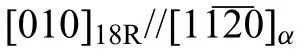

3.2.Strength and ductility of Mg-Y-Ho-Zn-Zr alloys

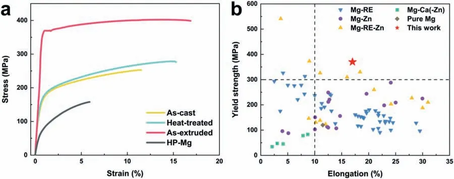
3.3.Corrosion resistance of Mg-Y-Ho-Zn-Zr alloys


3.4.Thermodynamics investigation of galvanic corrosion on Mg-Y-Ho-Zn-Zr alloys


3.5.Corrosion behavior in electrochemical testing


4.Discussion
4.1.Origin of high strength and ductility
4.2.Origin of uniform corrosion and low corrosion rate
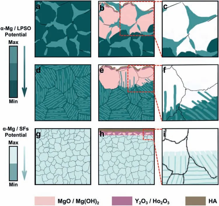

4.3.Interaction mechanism between HA and RE ions
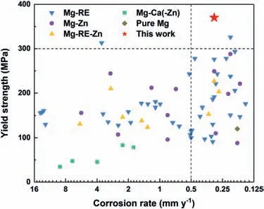
4.4.Trade-off analysis of corrosion resistance and strength
5.Conclusion
杂志排行

Journal of Magnesium and Alloys的其它文章
- Development of high-strength magnesium alloys with excellent ignition-proof performance based on the oxidation and ignition mechanisms: A review
- Development and application of magnesium alloy parts for automotive OEMs: A review
- Recent advances in surface endothelialization of the magnesium alloy stent materials
- Recent developments in high-pressure die-cast magnesium alloys for automotive and future applications
- Exploring the contribution of oxygen reduction reaction to Mg corrosion by modeling assisted local analysis
- Microstructures,mechanical properties,corrosion,and biocompatibility of extruded Mg-Zr-Sr-Ho alloys for biodegradable implant applications